Transcription
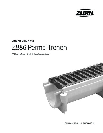
LI N E AR D R AI NAG EZ886 Perma-Trench6" Perma-Trench Installation Instructions
Z886 PERMA-TRENCHINSTALLATION INSTRUCTIONSZ886 Accessories6" [152MM] WIDE TRENCH DRAIN SYSTEMBelow are the components of the Z886 trench drain typicalto an installation. Check your order to verify you have allcomponents particular to your job before beginning yourinstallation. Contact customer service at 855-ONE-ZURN shouldadditional material be required.P887-INLET-6Inlet Adapter (IA)For Catch Basin ApplicationsShipping andInstallation BarP6-DGC6" [152] Double IronClass C GrateP886-E4-NS4" [102]No-HubEnd OutletGLGrate LockdownHardwareGrate Lockdown Bar(840 Bag)P886-JC-NSJoint ConnectorFor Use When Creating High or Low PointsP886-U4-NS4" [102] No-HubBottom OutletP886-E1-NSClosed End Cap2
Z886 PERMA-TRENCHINSTALLATION INSTRUCTIONSZ886 Tools RequiredTape MeasurePhillips Head ScrewdriverCordless DrillHammerReciprocating SawGlovesUtility KnifeEar ProtectionHole SawMarkerSafety GlassesCaulk Gun3
Z886 PERMA-TRENCHINSTALLATION INSTRUCTIONSZ886 EncasementA 4" [102] new concrete encasement is minimum. Guidelinesfor reinforcing an encasement would be to use the samethick-ness and reinforcing used in the surrounding concreteslab. Concrete must be vibrated to remove air voids inencasement, especially under the frame rails.Specifying engineer is responsible for concrete encasementand reinforcing based upon application and local codes.ExcavationTrench excavation must include the minimum of 4" [102] onboth sides and underneath or the slab thickness surroundingthe trench. Soft and/or shifting soil substrates may causecracking of the concrete and consequent movement ofthe trench. It is critical that the concrete be poured on anadequate foundation. Verify depth of trench excavation toallow for the same thickness of concrete under and besidethe trench as the surrounding slab thickness.44 [102]MIN.6-1/4 [159]4 [102]INVERT1-1/4 [32]4 [102]MIN.
Z886 PERMA-TRENCHINSTALLATION INSTRUCTIONSZ886 LayoutUpon completion of the excavation, the channel shouldbe placed in numeric order alongside the excavationaccording to the job layout. Each trench section has a trenchidentification number and flow direction indicating itssequence within the system. It is best to work from the deepor outlet end to the shallow. Grates are not installed at thistime.Four (4) shipping/installation bars per channel;recommended spacing is approximately 3"-6" [76-152] fromend of rail for end pieces and 26"-29" [660-737] from end ofrail for center pieces. All shipping/installation bar locationsare approximate.Must be installed onchannels without HDor HDS framesFemale End5
Z886 PERMA-TRENCHINSTALLATION INSTRUCTIONSZ886 End OutletConnection Options1When installing end cap or end outlet, removeby cutting with saw the 1-1/4" [32] male overlapconnection as shown.ScrapScrap2 Once overlap is removed, trim end cap/end outletto desired height.3 Attach end outlet or end cap to the channel withhardware provided.ATTACHING END CAPS AND OUTLETSMake sure all overlaps on trench are trimmed off prior toinstalling the end caps to ensure the finish installation hasa frame above the trench channel. This ensures each trenchwill have a grate on it.6Scrap
Z886 PERMA-TRENCHINSTALLATION INSTRUCTIONSZ886 Bottom Outlet Connection OptionScrapScrap1Score both sides of the rib with the utility knife.2 Tap rib with a hammer to remove rib when necessary.Scrap3 Attach bottom outlet to channel with hardware provided.4 Cut out hole with hole saw that matches inside diameterof outlet.7
Z886 PERMA-TRENCHINSTALLATION INSTRUCTIONSZ886Channel ConnectionZ886 Neutral CutChannel ConnectionScrap1.2.813"[25"[32]1]Scrap1When job layout calls for male-to-male channelconnection, cut male ends to be flush with end of integralframe on the ends that will be connected.1Cut a 1-1/4" [32] by 13/16" [21] section out of the end ofthe channel. This enables the end to act as a male end.Scrap51.23".812 Screw the ribs together with the hardware provided.This method can also be used if you have a female-tofemale connection.8[2"[32]1]2 After removing the cutouts, attach channel throughthe female connection with hardware provided.
Z886 PERMA-TRENCHINSTALLATION INSTRUCTIONSZ886 Connectingthe TrenchZ886-HDChannel ConnectionWITH JOINT CONNECTORScrap1ScrapCut joint connector to height. It should fit snug on theradius portion of the trench to just below the upper lip ofthe channel.2 Attach to the channels with the hardware provided.1When job layout calls for female-to-female channelconnection with HD frame, cut female ends to be flushwith end of the HD frame on the ends that will beconnected.2 Screw the joint connector to the channel with thehardware provided. This method can also be used if youhave a male-to-male connection. Ends are not cut off, butribs will need to be trimmed (See page 7).9
Z886 PERMA-TRENCHINSTALLATION INSTRUCTIONSZ886 Connecting theTrench with Sidewalls1When using sidewalls with a joint connector, be sure tokeep the trimmed pieces to attach to the sidewall portionof the trench using the hardware provided.Z886 Connectingthe Trench2 Attach to the channels with the hardware provided.Non-HD FrameChannels should be installed from deep or outlet endto shallow end. This allows the next shallower channel’smale connection to easily set onto the previous channellip. Stake in place with No. 4 rebar (by others) and attachwith the provided connection hardware.SEALING Channel connections are designed to be a good seal,meaning concrete aggregate will not intrude intothe trench. Silicone sealant may be used as a gasket between thechannels for a better seal. Channel connections may be welded with an HDPEwelding gun for the best seal.CONNECTIONS The maximum gap between frames is 1/4" [6].Rebar length dictated by trench depth and substrate for positiveanchoring while setting to resist floating.10HD Frame
Z886 PERMA-TRENCHINSTALLATION INSTRUCTIONSZ886 Catch BasinsCUT CHANNEL INSTALL1To make connection to a basin, invert the basin andchannel and trace the outline of the channel onto thebasin. This should be done for all sizes of basins.Scrap2 Cutting the hole in the basin can be easily accomplishedwith the use of a hand saw or power reciprocating saw.Cut out the material inside of the traced area, includingthe upper lip under the frame. Do not cut the frame.Scrap3 After the channel outline is removed from the catch basin,cut the inlet adapter to the height of the hole in the basin.Secure the inlet adapter to the basin using the hardwareprovided. Be sure to use silicone caulk or constructionadhesive to seal the adapter to the basin.4 Slide the male end of the channel into the inlet adapter,attaching them together with the supplied hardware andsilicone caulk or construction adhesive.11
Z886 PERMA-TRENCHINSTALLATION INSTRUCTIONSZ886 Catch BasinsFULL CHANNEL INSTALL1To make connection to a basin, invert the basin andchannel and trace the outline of the channel onto thebasin. This should be done for all sizes of basins. Thenremove the mechanical joint.3 Slide the male end of the channel into the basin attachingthem together with the supplied hardware and siliconecaulk or construction adhesive through the ribbing.122 Cutting the hole in the basin can be easily accomplishedwith the use of a hand saw or power reciprocating saw.Cut out the material inside of the traced area.
Z886 PERMA-TRENCHINSTALLATION INSTRUCTIONSZ886 Catch BasinsFULL CHANNEL INSTALL WITH HEAVY-DUTY FRAME1To make connection to a basin, invert the basin andchannel and trace the outline of the channel onto thebasin. This should be done for all sizes of basins.2 Cutting the hole in the basin can be easily accomplishedwith the use of a hand saw or power reciprocating saw.Cut out the material inside of the traced area.ScrapScrap3 After the channel outline is removed from the catchbasin, cut the inlet adapter to just under the top of themechanical joint. Secure the inlet adapter to the basinusing the hardware provided. Be sure to use silicone caulkor construction adhesive to seal the adapter to the basin.4 Slide the male end of the channel into the inlet adapterattaching them together with the supplied hardware andsilicone caulk or construction adhesive.13
Z886 PERMA-TRENCHINSTALLATION INSTRUCTIONSZ886Setting the TrenchNEW CONSTRUCTIONTypically, a trench system is assembled from the outlet back.Starting with the deepest section or catch basin, set the firstchannel utilizing the integral rebar clip anchoring system.Rebar clips are on both sides of each trench drain for easyattachment to No. 4 rebar stakes. Slide the rebar into therebar clips. Then drive the stakes into the ground for positiveanchoring. Secure the trench to the rebar stakes with thehardware provided with bag No. 841.Adjust the trench to the desired elevation and repeat theprocess with the next channel.14Set trench on rebar 1" [25] above final grade — this allowsfinal elevation adjustment with a hammer prior to pouringconcrete.It is recommended to pour concrete the same day the trenchis set.Recess trench 1/8" [3] below finish grade to ensure positiveflow into trench grate.
Z886 PERMA-TRENCHINSTALLATION INSTRUCTIONSZ886Setting the TrenchBLOCKOUT, RETROFIT, HANGINGAn alternative means of installation is to suspend the trenchdrain as shown. Wooden braces to hang the trench run canbe attached to the drain body through the grate lockdownbars as illustrated below.A1/8" shim1or as required8" [3]shim or as required15
Z886 PERMA-TRENCHINSTALLATION INSTRUCTIONSZ886 ConcretePour and FinishRemove shipping/installationbars as you finish trowelingPour the concrete around the three sides of the trenchdrain. Be certain to adequately vibrate the concrete asit is being placed. Proper vibration will eliminate anyunwanted voids within the concrete pour. If sidewallsare used, a first and second pour are recommended.Verify layout is correct prior to pouring concrete.PLACING CONCRETE Adhere to check that the trench drain is in thelocation required per the layout drawings prior topouring concrete. Standard concrete practices with expansion andcrack induction joints shall be followed based uponlocal codes and standards. The trench drain shall not be used as anexpansion joint.75" [19]5.5" [140]The use of nominal 1x6 (3/4" x 5-1/2") [20 x 140] lumber supplied byothers may be used to keep channel clear during the concrete pour.Finish troweling should be done to set the top edge of thetrench drain 1/8" [3] below the floor grade. Remember tocompensate for the concrete shrink that may occur duringcure so that the edge of the trench drain does not protrudeabove the finished floor grade.16
Z886 PERMA-TRENCHINSTALLATION INSTRUCTIONSZ886 Internal SidewallExtension BracingINSTALLATION WITH SIDEWALL EXTENSIONSUse reinforcing every 10" [254] per bracing schedule(bracing provided by others).425"[10 TYP]Standard4’sStandard22 xx nedby InvertByInvert17
Z886 PERMA-TRENCHINSTALLATION INSTRUCTIONSZ886 Sidewall Concrete PourFULL CHANNEL INSTALL WITH HEAVY-DUTY FRAME1Set the channel to the correct height.3 Using the standard concrete pouring method,pour concrete so it is about 8" [204] from the topof the trench.2 Install reinforcing per bracing schedule(bracing provided by others).4 Remove internal sidewall bracing.6.25 [159]POUR 24 [102]MIN.4 [102]8 [203]5 Pour the remaining concrete, remove shipping/installation bars, and use standard finishing practicesto finish the concrete.18POUR 1
Z886 PERMA-TRENCHINSTALLATION INSTRUCTIONSZ886Installing GratesAfter the concrete has been poured, vibrated, and givensufficient time to dry, grate lockdown bolts must beinstalled. The center of the grate should straddle the tiestrap that spans the frame. The exception is when bothchannels and frames are cut. To place these grates, lineup the lockdown hole in the grate with the lockdownhole in the tie strap. Lockdown bolts can be installedusing a 1/2" [13] socket.LOCKING DOWN GRATES Start all lockdown bolts on each grate into thelockdown prior to tightening them down. There may be gaps up to 1/4" [6] to ensure all grateswill lockdown.19
WARNING: Cancer and Reproductive Harm - www.P65Warnings.ca.govADVERTENCIA: Cáncer y daño reproductivo - www.P65Warnings.ca.govAVERTISSEMENT: Cancer et effets néfastes sur la reproduction www.P65Warnings.ca.govZURN INDUSTRIES, LLC Trench Drainage Operation1801 Pittsburgh Avenue, Erie, PA 16502, 855.663.9876In Canada: ZURN INDUSTRIES LIMITED 7900 Goreway Drive, Unit 10, Brampton, Ontario L6T 5W6, 877.892.5216Form No. ZMKTG220-11, 5/18
6" [152MM] WIDE TRENCH DRAIN SYSTEM Below are the components of the Z886 trench drain typical to an installation. Check your order to verify you have all components particular to your job before beginning your installation. Contact customer service at 855-ONE-ZURN should additio

