Transcription
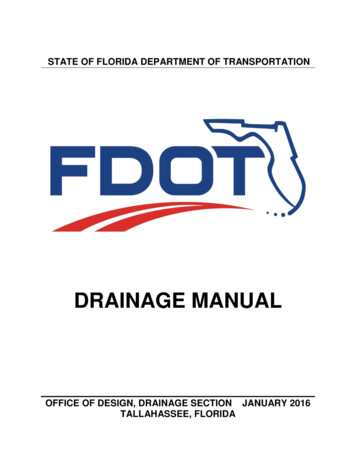
STATE OF FLORIDA DEPARTMENT OF TRANSPORTATIONDRAINAGE MANUALOFFICE OF DESIGN, DRAINAGE SECTION JANUARY 2016TALLAHASSEE, FLORIDA
Topic No. 625-040-002Drainage ManualEffective: January 2016TABLE OF CONTENTSChapter 1 Introduction . 41.1Purpose . 41.2Authority . 41.3Scope . 41.4General . 41.5Documentation of Drainage Design . 51.6Appendices . 51.7Distribution . 61.8Procedure for Revisions and Updates. 61.9Training . 61.10 Forms Access . 6Chapter 2 Open Channel . 72.1Introduction . 72.2Design Frequency . 72.3Hydrologic Analysis . 72.4Hydraulic Analysis . 82.4.1 Manning's "n" Values . 82.4.2 Slope. 82.4.3 Channel Linings and Velocity . 82.4.3.1 Limitations on Use of Linings . 92.4.4 Channel Bottom . 102.4.5 Channel Freeboard . 102.5Construction and Maintenance Considerations . 102.6Safety . 112.6.1 Protective Treatment. 112.6.2 Roadside Safety. 112.7Documentation . 11Chapter 3 Storm Drain Hydrology and Hydraulics . 153.1Introduction . 153.2Pipe Materials . 153.3Design Frequency . 153.4Design Tailwater . 163.4.1 Sea Level Rise . 173.5Hydrologic Analysis . 203.5.1 Time of Concentration. 203.6Hydraulic Analysis . 203.6.1 Pipe Slopes . 203.6.2 Hydraulic Gradient . 203.6.3 Outlet Velocity . 211
Topic No. 625-040-002Drainage Manual3.73.83.93.103.113.123.13Effective: January 20163.6.4 Manning's Roughness Coefficients . 21Hydraulic Openings and Protective Treatment . 223.7.1 Entrance Location and Spacing . 243.7.2 Manholes . 253.7.3 Shoulder Gutter. 253.7.4 Inlet Placement . 26Grades . 303.8.1 Longitudinal Gutter Grade . 30Spread Standards . 303.9.1 Spread for Permanent Construction. 303.9.2 Spread for Temporary Construction . 30Construction and Maintenance Considerations . 313.10.1 Pipe Size and Length . 313.10.2 Minimum Clearances . 323.10.3 Pipe Joint Designs Greater than 5 psi. 33Pipes within or Adjacent to Retained Earth (Walled) EmbankmentSections . 34Additional Design Considerations . 343.12.1 Noise Walls . 343.12.2 French Drains . 343.12.3 Resilient Connectors . 35Documentation . 363.13.1 Tabulation Form . 363.13.2 Other Documentation . 36Chapter 4 Cross Drain Hydraulics . 384.1Introduction . 384.2General . 384.2.2 LRFD Design Code Bridge Design Specifications. 394.3Design Frequency . 394.3.1 Permanent Facilities . 394.3.2 Temporary Facilities. 394.4Backwater . 404.5Tailwater . 404.6Clearances . 414.7Hydrologic Analysis . 414.7.1 Freshwater Flow . 414.7.2 Tidal Flow . 414.8Hydraulic Analysis . 424.8.1 Riverine Crossings . 424.8.2 Tidal Crossings . 424.9Specific Standards Relating to Bridges . 434.9.1 Berms for Spill-Through Abutment Bridges . 432
Topic No. 625-040-002Drainage Manual4.104.11Effective: January 20164.9.2 Scour Estimates . 434.9.3 Scour Protection Considerations. 464.9.4 Bridge Deck Drainage . 484.9.5 Wave and Current Forces on Coastal Bridges . 48Specific Standards relating to all Cross Drains except Bridges. 494.10.1 Culvert Materials . 494.10.2 Manning’s Roughness Coefficients . 494.10.3 End Treatment . 504.10.4 Construction and Maintenance Considerations . 50Documentation . 514.11.1 Culverts (all culverts less than a 20' bridge culvert) . 514.11.2 Bridges . 524.11.3 Document Processing . 55Chapter 5 Stormwater Management . 565.1Introduction . 565.2Regulatory Requirements . 565.2.1 Chapter 14-86, Florida Administrative Code . 565.2.2 Section 373.4596, Florida Statutes . 565.2.3 Chapter 62-25, Florida Administrative Code . 565.2.4 Chapter 62-40, Florida Administrative Code . 565.2.5 National Pollutant Discharge Elimination System . 575.3Environmental Look Arounds (ELA) . 575.4Design Standards. 585.4.1 Design of Systems . 585.4.2 Hydrologic Methods . 605.4.3 Protective Treatment. 605.4.4 Construction and Maintenance Considerations . 605.5Documentation . 63Chapter 6 Optional Culvert Materials . 656.1Introduction . 656.2Durability . 656.2.1 Culvert Service Life Estimation . 666.3Structural Evaluation . 666.4Hydraulic Evaluations. 666.5Culvert Material Types . 676.6Jack and Bore . 686.7Documentation . 68Appendix A Drainage Law . 71Appendix B Acquisition of Real Property Rights . 87Appendix C Cover Height Tables . 91Appendix D Pipes within Walled Embankment Sections . 1113
Topic No. 625-040-002Drainage ManualEffective: January 2016Chapter 1Introduction1.1PurposeThe Drainage Manual sets forth drainage design standards for Florida Department ofTransportation (FDOT) projects.1.2AuthorityChapter 334, Florida Statute (F.S.) Sections 20.23(4)(a) and 334.048(3), FloridaStatutes (F.S.)1.3ScopeThe principal users of this Manual are consultants and FDOT personnel who prepareFDOT construction plans.1.4GeneralChapter 334, F.S., known as the Florida Transportation Code, establishes theresponsibilities of the State, counties, and municipalities for the planning anddevelopment of the transportation systems serving the people of Florida, with theobjective of assuring development of an integrated, balanced statewide system. TheCode's purpose is to protect the safety and general welfare of the people of the State andto preserve and improve all transportation facilities in Florida. Under Section 334.044,F.S., the Code sets forth the powers and duties of the Department of Transportation todevelop and adopt uniform minimum standards and criteria for the design, construction,maintenance, and operation of public roads.The standards in this Manual provide a basis for uniform design practice for typicalroadway drainage design situations. Realizing that drainage design is primarily a matterof sound application of good engineering judgment, it is impossible to give precise ruleswhich would apply to all possible situations that may arise. Situations will exist wherethese standards will not apply. THE INAPPROPRIATE USE OF AND/OR ADHERENCETO THESE STANDARDS DOES NOT EXEMPT THE ENGINEER FROM THEPROFESSIONAL RESPONSIBILITY OF DEVELOPING AN APPROPRIATE DESIGN.The engineer is responsible for identifying those standards that do not apply to a particulardesign, and to obtain approval to deviate from those standards. Deviation from a standardin this Manual must be approved by the District Drainage Engineer. The request for4
Topic No. 625-040-002Drainage ManualEffective: January 2016deviation shall include the engineering gsregs/directives/fapg/cfr0650a.htm)prescribes the Federal Highway Administration (FHWA) policies and procedures for thelocation and hydraulic design of highway encroachments on flood plains. While thestandards presented in the FDOT Drainage Manual conform to Federal requirements,drainage designers are advised to become familiar with 23 CFR 650A to develop a basicunderstanding of some of the design standards for cross drains and bridges.Statistical rainfall depth data for Florida is found in NOAA Atlas 14 Rainfall Data. Thisdata is available at http://hdsc.nws.noaa.gov/hdsc/pfds/pfds map cont.html?bkmrk fl.FDOT Rainfall distributions and intensity-duration-frequency curves may be found es/IDFCurves.pdf.1.5Documentation of Drainage DesignApprovals of deviation from the Manual shall be included in the project drainage designdocumentation along with supporting justifications. The hydraulic designer shall providethe Department a signed and sealed Drainage Design Report that addresses the entireproject design. It shall be a record set of all drainage computations, both hydrologic andhydraulic and shall include all necessary support data. The Drainage Design Report shallinclude, at a minimum, pond routing calculations in ICPR or equivalent software, withjustifications of all tailwater stages utilized, a clear description of the overall stormwatermanagement system, storm drain tabulations in Department format, pond recoverycalculations, hydraulic spread calculations, special gutter grade calculations, drainagestructure and liner flotation calculations, ditch conveyance calculations, a node-reachdiagram superimposed on Department drainage maps, skimmer calculations, cross draincalculations and other calculations relative to drainage.Modification for Non-conventional Projects:The hydraulic designer shall provide the Department a Drainage Design Report toaccompany all phase submittals (which shall be signed and sealed at the Final Phasesubmittal) that addresses the entire project design.1.6AppendicesIncluded with this Manual are four appendices:Appendix A contains a general overview of drainage law with discussion of case historiesin Florida. It is provided as an appendix rather than a chapter since it is primarilyinformational and does not constitute a standard.5
Topic No. 625-040-002Drainage ManualEffective: January 2016Appendix B contains guidance on general FDOT practice with regard to acquisition ofdrainage easements, flood rights, etc.Appendix C contains minimum and maximum cover heights for design.Appendix D contains policy on the selection of pipes in proximity to structural walls.1.7DistributionThis Manual is available for downloading from the website /files/DrainageManual.pdf1.8Procedure for Revisions and UpdatesComments and suggestions for changes to the Manual are invited to be submitted by emailing the State Drainage Engineer. Appropriate Roadway Design or Drainage Designstaff will review each idea or suggestion received in a timely manner.Statewide meetings of the District Drainage Engineers and the State Drainage Engineerare held at least annually and teleconferences are held monthly. A major agenda item atthese meetings will be the review of planned revisions, and suggestions and commentsthat may warrant revisions. Based on input from these meetings, official proposedrevisions are developed.The State Drainage Engineer will coordinate the proposed revisions with all the affectedoffices and with FHWA. Official adoption of the proposed revisions is made by StateDrainage Engineer with input from the District Drainage Engineers.Prior to release, all revisions will be coordinated with the Forms and Procedures Office toensure conformance with and incorporation into the Department’s Standard OperatingSystem.1.9TrainingThere is no mandatory training required.1.10Forms AccessThere are no forms related to this manual.6
Topic No. 625-040-002Drainage ManualEffective: January 2016Chapter 2Open Channel2.1IntroductionThis chapter presents standards for the design of artificial or manmade open channels,including roadside ditches, median ditches, interceptor ditches, outfall ditches, andcanals.2.2Design FrequencyOpen channels shall be designed to convey, without damage, and to confine within theditch, stormwater flow with standard design frequencies as follows:TYPE CHANNELFREQUENCYRoadside, Median, and Interceptor ditches or swales10-yearOutfalls (piped or open)25-yearCanals25-yearTemporary roadside and median ditches or swales2-yearTemporary Outfalls and Canals5-yearSite-specific factors may warrant the use of an atypical design frequency. Any increaseover pre-development stages shall not change offsite land use values, unless flood rightsare acquired.2.3Hydrologic AnalysisHydrologic data used for the design of open channels shall be based on one of thefollowing methods, as appropriate, for the particular site:1. A frequency analysis of observed (gage) data shall be used when available. Ifinsufficient or no observed data is available, one of the procedures below shallbe used as appropriate. However, the procedures below shall be calibrated tothe extent practical with available observed data for the drainage basin, or7
Topic No. 625-040-002Drainage ManualEffective: January 2016nearby similar drainage basins.a.Regional or local regression equation developed by the USGS.b.Rational Equation for drainage areas up to 600 acres.c.For outfalls from stormwater management facilities, the method used forthe design of the stormwater management facility may be used. SeeChapter 5 for hydrologic methods that may be used for the design ofstormwater management facilities.2. For regulated or controlled canals, hydrologic data shall be requested from thecontrolling entity. Prior to use for design, this data shall be verified to the extentpractical.2.4Hydraulic AnalysisThe Manning's Equation shall be used for the design of open channels.2.4.1Manning's "n" ValuesManning's n values for channels with bare soil and vegetative linings are presented inTable 2.1. Manning's n values for rigid linings are presented in Table 2.2.The probable condition of the channel when the design event is anticipated shall beconsidered when a Manning's n value is selected. Ditches with bottoms designed at ornear the seasonal high groundwater level shall use the higher "n" values to account forincreased vegetation growth occurring between extended maintenance periods.2.4.2SlopeFor ditches where positive flow conditions are required, a minimum physical slope of0.0005 ft/ft shall be used.2.4.3Channel Linings and VelocityThe design of open channels shall determine the need for channel linings. Standardlining types are shown in Design Standard Index 281 and Standard Specifications forRoad and Bridge Construction Section 985. Maximum velocities for the various formsof channel lining are given in Tables 2.3 and 2.4. When design flow velocities do notexceed the maximum permissible for bare earth as given in Table 2.3, standard treatmentof ditches consists of grassing and mulching. For higher design velocities, sodding, ditchpaving, or other form of lining consistent with Tables 2.3 and 2.4 shall be provided.8
Topic No. 625-040-002Drainage ManualEffective: January 2016Shear stress shall be checked at locations of steep slopes ( 1%) such as ditch flow downa pond slope, gore drainage, and offsite flow entering the right of way via the back slopeof a roadside swale.The Open Channel Handbook provides additional guidance on types of lining materialsas well as the proper application of various types of linings.2.4.3.1Limitations on Use of Linings2.4.3.1.1 Grassing and SoddingGrassing or sodding shall not be used under the following conditions:1.Continuous standing or flowing water2.Areas that do not receive the regular maintenance necessary to preventdomination by taller vegetation3.Lack of nutrients and excessive soil drainage4.Areas excessively shaded2.4.3.1.2 Concrete LiningTo prevent cracking or failure, concrete lining must be placed on a firm, well-drainedfoundation. Concrete linings shall not be used where expansive clays are present.When concrete linings are to be used where soils may become saturated, the potentialfor buoyancy shall be considered. Acceptable countermeasures include:1.Increasing the thickness of the lining to add additional weight.2.For sub-critical flow conditions, specifying weep holes at appropriate intervals in the channel bottom to relieve the upward pressure on the channel.3.For super-critical flow conditions, using subdrains in lieu of weep holes.2. 4.3.1.3 Asphalt LiningAsphalt linings are for maintenance activities only and are not allowed for design projects.2.4.3.1.4 Turf Reinforcement Mat (TRM)Turf reinforcement mats shall not be used where high siltation is expected. During9
Topic No. 625-040-002Drainage ManualEffective: January 2016desilting operations the TRM may be damaged.2.4.4Channel BottomThe minimum channel bottom width is 5 ft to accommodate mitered end sections andmaintenance mowers. V-bottom ditches are not allowed due to their vulnerability to fillwith silt unless both front and back slopes are 1:6 or flatter.The minimum ditch bottom elevation shall be 1 foot above the estimated seasonal highgroundwater elevation for maintainability. Fine grained soils may require more than 1 ft.clearance from the seasonal high groundwater to enable mowing.2.4.5Channel FreeboardProvide a minimum of 1 ft of channel freeboard above the design stage within the channelif in a fill slope and 0.5 ft. if the channel is in a cut slope. If a channel is hydraulicallyconnected to or part of the stormwater management facility, provide no less than 1 footof channel freeboard above the peak design stage of the downstream, hydraulicallyconnected pond. Consider downstream tailwater in freeboard calculations.2.5Construction and Maintenance ConsiderationsThe design of an open channel shall be consistent with the standard construction andmaintenance practices of the Department. Standard ditch linings are detailed in theDesign Standard Index drawings and Standard Specifications. In the event the standardindex drawings and specifications are not suitable for a specific project need, a detaileddesign shall be developed. This information must be specified in the design documents.Ditches, outfall ditches retention/detention areas, and other drainage related featuresmust be provided with berms and other physical access devices that facilitatemaintenance activities. Consideration shall be given to future expansion of the facilitiesand to possible increased maintenance requirements. Absolute minimum values shouldonly be used in extremely stable areas, in areas requiring infrequent maintenance, or inareas where existing physical constraints require their use. Berms should be based atthe narrowest point; right-of-way should be reasonably uniform. If double ditches arespecified, the minimum berm width between the two ditches is 10 feet if the ditches aredry, 15ft if the ditches are wet, for maintenance access. Contact the local maintenanceoffice for minimum access requirements when the minimum berm width is not feasible10
Topic No. 625-040-002Drainage ManualEffective: January 20162.6Safety2.6.1Protective TreatmentDrainage designs shall be reviewed to determine if some form of protective treatment willbe required to prevent entry to facilities that present a hazard to children and, to a lesserextent, all persons. General criteria are provided in Section 3.7. Protective treatment foropen channels in the form of fencing shall be considered when a potential hazard exists.2.6.2Roadside SafetyThe design and location of open channels shall comply with roadside safety and clearzone requirements. See the Plans Preparation Manual for clear zone requirements,including special clearance criteria for canals.2.7DocumentationDesign documentation for open channels shall include the hydrologic analysis and thehydraulic analysis, including analysis of channel lining requirements. For roadsideditches, the required standard format for documentation is provided in Figure 2-1.Table 2.1Manning's "n" Values for Artificial Channelswith Bare Soil and Vegetative LiningsChannel LiningBare Earth, Fairly UniformBare Earth, Fairly UniformDragline ExcavatedDragline ExcavatedMaintained Grass orSodded DitchesChannels not MaintainedChannels not MaintainedMaintained Grass orSodded DitchesDescriptionDesign "n"Clean, recently completedShort grass and some weedsNo VegetationLight Brush0.020.030.030.04Good stand, well maintained 2 - 6"Clear bottom, brush sidesDense weeds to flow depth0.060.080.1Fair stand, length 12" - 24"0.2* Decrease 30 percent for flows 0.7' depth (max flow depth 1.5')Table 2.211
Topic No. 625-040-002Drainage ManualEffective: January 2016Manning's "n" Values for Artificial Channels with Rigid LiningsChannel LiningDescriptionDesign "n"Concrete PavedConcrete PavedConcrete PavedConcrete PavedRubble RiprapAsphalt ConcreteAsphalt ConcreteBroomed*"Roughened" - StandardGuniteOver RubbleDitch 16* Broomed is not the standard finish and must be specified when used (see Section 5247 of Standard Specifications)Table 2.3Maximum Shear Stress Valuesand Allowable Velocities for Different SoilsSoil TypeSilt or Fine SandSandy LoamSilt LoamFirm LoamStiff ClayHardpansShear Stress (psf)Allowable Velocityfor a flow depth ofabout 3 ft. 2.503.756.00Reference: University of Florida (1972)12
Topic No. 625-040-002Drainage ManualEffective: January 2016Table 2.4Maximum Velocities for Various Lining TypesLining TypeMaximum Velocity (fps)Grass with MulchBare Soil (Table 2.3)Sod4***Staked Sod5Lapped Sod5.5Erosion Control Blanket6.5(Biodegradable, Spec Section 104-6)Plastic Erosion Mat(Permanent, Spec Sections 571 and 985)- Type 110- Type 214- Type 318Riprap (Rubble)(Ditch Lining)6Other flexibleFHWA HEC-15Geotextile Grid4 - 8*Rigid10*** Varies with grid** Higher velocities acceptable with provisions for energy dissipation*** If long term turf density is expected to be poor, use 3 fps maximum velocity13
Topic No. 625-040-002Drainage ManualEffective: January 2016FLORIDA DEPARTMENT OF TRANSPORTATIONHYDRAULIC WORKSHEET FOR ROADSIDE DITCHESRoad:Project Number:STATION TO STATIONSIDENote: F.S. Front Slope%SlopeDrainArea“C”tCi10Sheet ofPrepared by: Date:Checked by: Date:Q(cfs)Ditch SectionF.S.B.W.B.S.B.W. Bottom Width“n”“d”“dallowed”Vel.(fps)B.S. Back SlopeFigure 2-114DitchLiningSideDrainPipeDia.Remarks
Topic No. 625-040-002Drainage ManualEffective: January 2016Chapter 3Storm Drain Hydrology and Hydraulics3.1IntroductionThis chapter presents minimum standards for the design of FDOT storm drain systems.3.2Pipe MaterialsPipe material selection shall be in accordance with Chapter 6 of this manual.3.3Design FrequencyStandard design storm frequencies for the design of storm drain systems are as follows:TYPE STORM DRAINFREQUENCYGeneral design 3-yearGeneral design work that involves replacement of aroadside ditch with a pipe system by extending sidedrain pipes General design on work to Interstate Facilities Interstate Facilities for which roadway runoff wouldhave no outlet other than a storm drain system, suchas in a sag inlet or cut section 10-year50-yearOutlets of systems requiring pumping stationsSite-specific factors may warrant the use of atypical design frequency. Any increase over predevelopment stages shall not significantly change land use values, unless flood rights areacquired.If a system has both curb inlets and ditch bottom inlets (DBI’s), the HGL for the DBI’s shall bechecked for a 10-year design frequency and all structures in the mixed system shall meet the 3year design frequency.15
Topic No. 625-040-002Drainage Manual3.4Effective: January 2016Design TailwaterFor the determination of hydraulic gradient and the sizing of storm drain conduits a tailwaterelevation, which can be reasonably expected to occur coincident with the design storm event shallbe used. Standard design tailwater conditions for the design of storm drain systems are asfollows:Crown of pipe at the outlet, or if higher:Lakes ---------------------Normal High WaterRivers and Streams --Normal High WaterStormwater Ponds ----Peak stage in the pond during th
Topic No. 625-040-002 Effective: January 2016 Drainage Manual 4 . Chapter 1 Introduction 1.1 Purpose . The . Drainage Manual. sets