Transcription
Ch01-P373588.tex1/2/200711: 361Page uction2Fourier’s Law of Heat Conduction2The Heat Conduction Equation6Thermal Resistance15The Conduction Shape Factor19Unsteady-State Conduction24Mechanisms of Heat Conduction31
Ch01-P373588.tex1/21/2/200711: 36Page 2H E AT C O N D U CT I O N1.1 IntroductionHeat conduction is one of the three basic modes of thermal energy transport (convection andradiation being the other two) and is involved in virtually all process heat-transfer operations. Incommercial heat exchange equipment, for example, heat is conducted through a solid wall (oftena tube wall) that separates two fluids having different temperatures. Furthermore, the concept ofthermal resistance, which follows from the fundamental equations of heat conduction, is widely usedin the analysis of problems arising in the design and operation of industrial equipment. In addition,many routine process engineering problems can be solved with acceptable accuracy using simplesolutions of the heat conduction equation for rectangular, cylindrical, and spherical geometries.This chapter provides an introduction to the macroscopic theory of heat conduction and its engineering applications. The key concept of thermal resistance, used throughout the text, is developedhere, and its utility in analyzing and solving problems of practical interest is illustrated.1.2 Fourier’s Law of Heat ConductionThe mathematical theory of heat conduction was developed early in the nineteenth century byJoseph Fourier [1]. The theory was based on the results of experiments similar to that illustratedin Figure 1.1 in which one side of a rectangular solid is held at temperature T1 , while the oppositeside is held at a lower temperature, T2 . The other four sides are insulated so that heat can flowonly in the x-direction. For a given material, it is found that the rate, qx , at which heat (thermalenergy) is transferred from the hot side to the cold side is proportional to the cross-sectional area,A, across which the heat flows; the temperature difference, T1 T2 ; and inversely proportional tothe thickness, B, of the material. That is:qx A(T1 T2 )BWriting this relationship as an equality, we have:qx k A(T1 T2 )B(1.1)InsulatedT2T1qxInsulatedqxBxInsulatedFigure 1.1 One-dimensional heat conduction in a solid.
Ch01-P373588.tex1/2/200711: 36Page 3H E AT C O N D U CT I O N1/3The constant of proportionality, k, is called the thermal conductivity. Equation (1.1) is also applicableto heat conduction in liquids and gases. However, when temperature differences exist in fluids, convection currents tend to be set up, so that heat is generally not transferred solely by the mechanismof conduction.The thermal conductivity is a property of the material and, as such, it is not really a constant, butrather it depends on the thermodynamic state of the material, i.e., on the temperature and pressureof the material. However, for solids, liquids, and low-pressure gases, the pressure dependence isusually negligible. The temperature dependence also tends to be fairly weak, so that it is oftenacceptable to treat k as a constant, particularly if the temperature difference is moderate. When thetemperature dependence must be taken into account, a linear function is often adequate, particularlyfor solids. In this case,k a bT(1.2)where a and b are constants.Thermal conductivities of a number of materials are given in Appendices 1.A–1.E. Many othervalues may be found in various handbooks and compendiums of physical property data. Processsimulation software is also an excellent source of physical property data. Methods for estimatingthermal conductivities of fluids when data are unavailable can be found in the authoritative bookby Poling et al. [2].The form of Fourier’s law given by Equation (1.1) is valid only when the thermal conductivitycan be assumed constant. A more general result can be obtained by writing the equation for anelement of differential thickness. Thus, let the thickness be x and let T T2 T1 . Substitutingin Equation (1.1) gives:qx k A T x(1.3)Now in the limit as x approaches zero, TdT xdxand Equation (1.3) becomes:qx k AdTdx(1.4)Equation (1.4) is not subject to the restriction of constant k. Furthermore, when k is constant, it canbe integrated to yield Equation (1.1). Hence, Equation (1.4) is the general one-dimensional form ofFourier’s law. The negative sign is necessary because heat flows in the positive x-direction whenthe temperature decreases in the x-direction. Thus, according to the standard sign convention thatqx is positive when the heat flow is in the positive x-direction, qx must be positive when dT /dx isnegative.It is often convenient to divide Equation (1.4) by the area to give:q̂x qx /A kdTdx(1.5)where q̂x is the heat flux. It has units of J/s · m2 W/m2 or Btu/h · ft2 . Thus, the units of k areW/m · K or Btu/h · ft · F.Equations (1.1), (1.4), and (1.5) are restricted to the situation in which heat flows in the x-directiononly. In the general case in which heat flows in all three coordinate directions, the total heat flux is
Ch01-P373588.tex1/41/2/200711: 36Page 4H E AT C O N D U CT I O Nobtained by adding vectorially the fluxes in the coordinate directions. Thus, q̂ q̂x i q̂y j q̂z k (1.6) where q̂ is the heat flux vector and i , j , k are unit vectors in the x-, y-, z-directions, respectively.Each of the component fluxes is given by a one-dimensional Fourier expression as follows:q̂x k T xq̂y k T yq̂z k T z(1.7)Partial derivatives are used here since the temperature now varies in all three directions. Substitutingthe above expressions for the fluxes into Equation (1.6) gives: T T T q̂ k (1.8)jik x y z The vector in parenthesis is the temperature gradient vector, and is denoted by T . Hence, q̂ k T(1.9)Equation (1.9) is the three-dimensional form of Fourier’s law. It is valid for homogeneous, isotropicmaterials for which the thermal conductivity is the same in all directions.Equation (1.9) states that the heat flux vector is proportional to the negative of the temperaturegradient vector. Since the gradient direction is the direction of greatest temperature increase, thenegative gradient direction is the direction of greatest temperature decrease. Hence, Fourier’s lawstates that heat flows in the direction of greatest temperature decrease.Example 1.1The block of 304 stainless steel shown below is well insulated on the front and back surfaces, andthe temperature in the block varies linearly in both the x- and y-directions, find:(a) The heat fluxes and heat flows in the x- and y-directions.(b) The magnitude and direction of the heat flux vector.5 cm15 C10 C5 cm10 cm5 C0 Cyx
Ch01-P373588.tex1/2/200711: 36Page 5H E AT C O N D U CT I O N1/5Solution(a) From Table A.1, the thermal conductivity of 304 stainless steel is 14.4 W/m · K. The crosssectional areas are:Ax 10 5 50 cm2 0.0050 m2Ay 5 5 25 cm2 0.0025 m2Using Equation (1.7) and replacing the partial derivatives with finite differences (since thetemperature variation is linear), the heat fluxes are:q̂x k T T 5 k 14.4 1440 W/m2 x x0.05q̂y k T10 T k 14.4 1440 W/m2 y y0.1The heat flows are obtained by multiplying the fluxes by the corresponding cross-sectionalareas:qx q̂x Ax 1440 0.005 7.2 Wqy q̂y Ay 1440 0.0025 3.6 W(b) From Equation (1.6): q̂ q̂x i q̂y j q̂ 1440 i 1440 j q̂ [(1440)2 ( 1440)2 ]0.5 2036.5 W/m2 The angle, θ, between the heat flux vector and the x-axis is calculated as follows:tan θ q̂y /q̂x 1440/1440 1.0θ 45 The direction of the heat flux vector, which is the direction in which heat flows, is indicated inthe sketch below.
Ch01-P373588.tex1/61/2/200711: 36Page 6H E AT C O N D U CT I O Nyx45 q1.3 The Heat Conduction EquationThe solution of problems involving heat conduction in solids can, in principle, be reduced to thesolution of a single differential equation, the heat conduction equation. The equation can be derivedby making a thermal energy balance on a differential volume element in the solid. For the case ofconduction only in the x-direction, such a volume element is illustrated in Figure 1.2. The balanceequation for the volume element is:{rate of thermal energy in} {rate of thermal energy out} {net rate of thermalenergy generation} {rate of accumulation of thermal energy}(1.10)The generation term appears in the equation because the balance is made on thermal energy, nottotal energy. For example, thermal energy may be generated within a solid by an electric currentor by decay of a radioactive material.The rate at which thermal energy enters the volume elementacross the face at x is given by the product of the heat flux and the cross-sectional area, q̂x x A. Similarly, the rate at which thermalenergy leaves the element across the face at x x is q̂x x x A. For a homogeneous heat sourceq̂ x xq̂x x x xxx xxFigure 1.2 Differential volume element used in derivation of conduction equation.
Ch01-P373588.tex1/2/200711: 36Page 7H E AT C O N D U CT I O N1/7of strength q̇ per unit volume, the net rate of generation is q̇A x. Finally, the rate of accumulationis given by the time derivative of the thermal energy content of the volume element, which isρc(T Tref )A x, where Tref is an arbitrary reference temperature. Thus, the balance equationbecomes:( q̂x x q̂x x x )A q̇A x ρc TA x tIt has been assumed here that the density, ρ, and heat capacity, c, are constant. Dividing by A xand taking the limit as x 0 yields:ρc T q̂x q̇ t xUsing Fourier’s law as given by Equation (1.5), the balance equation becomes: T k Tρc q̇ t x xWhen conduction occurs in all three coordinate directions, the balance equation contains y- andz-derivatives analogous to the x-derivative. The balance equation then becomes: T k T k T k Tρc q̇ t x x y y z z(1.11)Equation (1.11) is listed in Table 1.1 along with the corresponding forms that the equation takes incylindrical and spherical coordinates. Also listed in Table 1.1 are the components of the heat fluxvector in the three coordinate systems.When k is constant, it can be taken outside the derivatives and Equation (1.11) can bewritten as:ρc T 2 T 2 T 2 Tq̇ 2 2 2 kk t x y z(1.12)1 Tq̇ 2T α tk(1.13)orwhere α k/ρc is the thermal diffusivity and 2 is the Laplacian operator. The thermal diffusivityhas units of m2 /s or ft2 /h.
Ch01-P373588.tex1/81/2/200711: 36Page 8H E AT C O N D U CT I O NTable 1.1 The Heat Conduction EquationA.Cartesian coordinatesρc T t x k T x y k T y zk T z q̇ The components of the heat flux vector, q̂ , are:q̂x kB. T xq̂y k T yq̂z k T zCylindrical coordinates (r, φ, z)z(x, y, z) (r, φ, z)yφrxρc 1 T1 T T T kr 2k k q̇ tr r r φ z zr φ The components of q̂ are:q̂r kC. T; r k T;r φq̂φ q̂z kSpherical coordinates (r, θ, φ)zrθ(x, y, z) (r, θ, φ)yφx T z
Ch01-P373588.tex1/2/200711: 36Page 9H E AT C O N D U CT I O Nρc1/9 1 T T 2k sin θ r θr sin θ θ 1 T k q̇22 φ φr sin θ1 T 2 tr r k r2 The components of q̂ are:q̂r k T; rq̂θ k T;r θq̂φ k Tr sin θ φThe use of the conduction equation is illustrated in the following examples.Example 1.2Apply the conduction equation to the situation illustrated in Figure 1.1.SolutionIn order to make the mathematics conform to the physical situation, the following conditions areimposed:(1) Conduction only in x-direction T T(x), so(2) No heat source q̇ 0 T(3) Steady state 0 t(4) Constant k T T 0 y zThe conduction equation in Cartesian coordinates then becomes:0 k 2 T x 2ord2T 0dx 2(The partial derivative is replaced by a total derivative because x is the only independent variablein the equation.) Integrating on both sides of the equation gives:dT C1dxA second integration gives:T C1 x C 2Thus, it is seen that the temperature varies linearly across the solid. The constants of integrationcan be found by applying the boundary conditions:(1) At x 0 T T1(2) At x B T T2The first boundary condition gives T1 C2 and the second then gives:T 2 C1 B T 1
Ch01-P373588.tex1 / 101/2/200711: 36Page 10H E AT C O N D U CT I O NSolving for C1 we find:C1 T2 T1BThe heat flux is obtained from Fourier’s law:q̂x k T2 T 1T1 T 2dT kC1 k kdxBBMultiplying by the area gives the heat flow:qx q̂x A kA(T1 T2 )BSince this is the same as Equation (1.1), we conclude that the mathematics are consistent with theexperimental results.Example 1.3Apply the conduction equation to the situation illustrated in Figure 1.1, but let k a bT , where aand b are constants.SolutionConditions 1–3 of the previous example are imposed. The conduction equation then becomes: ddT0 kdxdxIntegrating once gives:kdT C1dxThe variables can now be separated and a second integration performed. Substituting for k, wehave:(a bT )dT C1 dxaT bT 2 C1 x C22It is seen that in this case of variable k, the temperature profile is not linear across the solid.The constants of integration can be evaluated by applying the same boundary conditions as in theprevious example, although the algebra is a little more tedious. The results are:C2 aT1 C1 abT122b(T2 T1 ) (T 2 T12 )B2B 2
Ch01-P373588.tex1/2/200711: 36Page 11H E AT C O N D U CT I O N1 / 11As before, the heat flow is found using Fourier’s law:dT AC1qx kAdx Ab 22qx a(T1 T2 ) (T1 T2 )B2This equation is seldom used in practice. Instead, when k cannot be assumed constant, Equation(1.1) is used with an average value of k. Thus, taking the arithmetic average of the conductivities atthe two sides of the block:k(T1 ) k(T2 )2(a bT1 ) (a bT2 ) 2bkave a (T1 T2 )2kave Using this value of k in Equation (1.1) yields:kave A(T1 T2 )B b(T1 T2 ) A a (T1 T2 )2B Abqx a(T1 T2 ) (T12 T22 )B2qx This equation is exactly the same as the one obtained above by solving the conduction equation.Hence, using Equation (1.1) with an average value of k gives the correct result. This is a consequenceof the assumed linear relationship between k and T .Example 1.4Use the conduction equation to find an expression for the rate of heat transfer for the cylindricalanalog of the situation depicted in Figure 1.1.SolutionqrrT1R1T2qrR2
Ch01-P373588.tex1 / 121/2/200711: 36Page 12H E AT C O N D U CT I O NAs shown in the sketch, the solid is in the form of a hollow cylinder and the outer and inner surfacesare maintained at temperatures T1 and T2 , respectively. The ends of the cylinder are insulated sothat heat can flow only in the radial direction. There is no heat flow in the angular (φ) directionbecause the temperature is the same all the way around the circumference of the cylinder. Thefollowing conditions apply:(1) No heat flow in z-direction T 0 z(2) Uniform temperature in φ-direction (3) No heat generation q̇ 0 T(4) Steady state 0 t(5) Constant k T 0 φWith these conditions, the conduction equation in cylindrical coordinates becomes: T1 kr 0r r ror dTdr 0drdrIntegrating once gives:dT C1drSeparating variables and integrating again gives:rT C1 ln r C2It is seen that, even with constant k, the temperature profile in curvilinear systems is nonlinear.The boundary conditions for this case are:(1) At r R1 T T1 T1 C1 ln R1 C2(2) At r R2 T T2 T2 C1 ln R2 C2Solving for C1 by subtracting the second equation from the first gives:C1 T 1 T2T1 T2 ln R1 ln R2ln(R2 /R1 )From Table 1.1, the appropriate form of Fourier’s law is:q̂r kC1k(T1 T2 )dT k drrr ln(R2 /R1 )The area across which the heat flows is:Ar 2πrLwhere L is the length of the cylinder. Thus,qr q̂r Ar 2πkL(T1 T2 )ln(R2 /R1 )
Ch01-P373588.tex1/2/200711: 36Page 13H E AT C O N D U CT I O N1 / 13Notice that the heat-transfer rate is independent of radial position. The heat flux, however, dependson r because the cross-sectional area changes with radial position.Example 1.5The block shown in the diagram below is insulated on the top, bottom, front, back, and the side atx B. The side at x 0 is maintained at a fixed temperature, T1 . Heat is generated within the blockat a rate per unit volume given by:q̇ e γxwhere , γ 0 are constants. Find the maximum steady-state temperature in the block. Data are asfollows: 10 W/m3γ 0.1 m 1B 1.0 mT1 20 Ck 0.5 W/m · K block thermal conductivityInsulatedInsulatedInsulatedT1Bxx 0Insulatedx BSolutionThe first step is to find the temperature profile in the block by solving the heat conduction equation.The applicable conditions are: Steady state Conduction only in x-direction Constant thermal conductivityThe appropriate form of the heat conduction equation is then:d(kdT/dx) q̇ 0dxkd2T e γx 0dx 2d2T e γx kdx 2Integrating once gives:dT e γx C1dxkγ
Ch01-P373588.tex1 / 141/2/200711: 36Page 14H E AT C O N D U CT I O NA second integration yields:T e γx C1 x C 2kγ 2The boundary conditions are:(1) At x 0 T T1dT(2) At x B 0dxThe second boundary condition results from assuming zero heat flow through the insulatedboundary (perfect insulation). Thus, at x L:qx kAdT 0dx dT 0dxThis condition is applied using the equation for dT/dx resulting from the first integration:0 e γB C1kγHence,C1 e γBkγApplying the first boundary condition to the equation for T :T1 e(0) C1 (0) C2kγ 2Hence,C2 T1 kγ 2With the above values for C1 and C2 , the temperature profile becomes:T T1 e γB(1 e γx ) x2kγkγNow at steady state, all the heat generated in the block must flow out through the un-insulated sideat x 0. Hence, the maximum temperature must occur at the insulated boundary, i.e., at x B.(This intuitive result can be confirmed by setting the first derivative of T equal to zero and solvingfor x.) Thus, setting x B in the last equation gives:Tmax T1 BLe γB γB(1 e) kγkγ 2Finally, the solution is obtained by substituting the numerical values of the parameters:Tmax 20 1010 1.0 e 0.1 0.1(1 e) 0.5 0.10.5(0.1)2Tmax 29.4 C
Ch01-P373588.tex1/2/200711: 36Page 15H E AT C O N D U CT I O N1 / 15The procedure illustrated in the above examples can be summarized as follows:(1) Write down the conduction equation in the appropriate coordinate system.(2) Impose any restrictions dictated by the physical situation to eliminate terms that are zero ornegligible.(3) Integrate the resulting differential equation to obtain the temperature profile.(4) Use the boundary conditions to evaluate the constants of integration.(5) Use the appropriate form of Fourier’s law to obtain the heat flux.(6) Multiply the heat flux by the cross-sectional area to obtain the rate of heat transfer.In each of the above examples there is only one independent variable so that an ordinary differentialequation results. In unsteady-state problems and problems in which heat flows in more than onedirection, a partial differential equation must be solved. Analytical solutions are often possible ifthe geometry is sufficiently simple. Otherwise, numerical solutions are obtained with the aid of acomputer.1.4 Thermal ResistanceThe concept of thermal resistance is based on the observation that many diverse physicalphenomena can be described by a general rate equation that may be stated as follows:Flow rate Driving forceResistance(1.14)Ohm’s Law of Electricity is one example:I ER(1.15)In this case, the quantity that flows is electric charge, the driving force is the electrical potentialdifference, E, and the resistance is the electrical resistance, R, of the conductor.In the case of heat transfer, the quantity that flows is heat (thermal energy) and the driving forceis the temperature difference. The resistance to heat transfer is termed the thermal resistance, andis denoted by Rth . Thus, the general rate equation may be written as:q TRth(1.16)In this equation, all quantities take on positive values only, so that q and T represent the absolutevalues of the heat-transfer rate and temperature difference, respectively.An expression for the thermal resistance in a rectangular system can be obtained by comparingEquations (1.1) and (1.16):qx kA(T1 T2 )T1 T2 T BRthRth(1.17)BkA(1.18)Rth Similarly, using the equation derived in Example 1.4 for a cylindrical system gives:qr 2πkL(T1 T2 )T1 T2 ln(R2 /R1 )Rth(1.19)
Ch01-P373588.tex1 / 161/2/200711: 36Page 16H E AT C O N D U CT I O NTable 1.2 Expressions for Thermal ResistanceConfigurationRthConduction, CartesiancoordinatesB/kAln(R2 /R1 )2πkLConduction, radial direction,cylindrical coordinatesR2 R14πk R1 R2Conduction, radial direction,spherical coordinatesConduction, shape factor1/kSConvection, un-finned surface1/hAConvection, finned surface1hηw AS shape factorh heat-transfer coefficientηw weighted efficiency of finned surface Ap prime surface areaAp ηf AfAp AfAf fin surface areaηf fin efficiencyln(R2 /R1 )(1.20)2πkLThese results, along with a number of others that will be considered subsequently, are summarizedin Table 1.2. When k cannot be assumed constant, the average thermal conductivity, as defined inthe previous section, should be used in the expressions for thermal resistance.The thermal resistance concept permits some relatively complex heat-transfer problems to besolved in a very simple manner. The reason is that thermal resistances can be combined in thesame way as electrical resistances. Thus, for resistances in series, the total resistance is the sum ofthe individual resistances: RTot Ri(1.21)Rth iLikewise, for resistances in parallel:RTot 11/Ri(1.22)iThus, for the composite solid shown in Figure 1.3, the thermal resistance is given by:Rth RA RBC RD(1.23)where RBC , the resistance of materials B and C in parallel, is: 1 RBC 1/RB 1/RCR B RCRB R C(1.24)
Ch01-P373588.tex1/2/200711: 36Page 17H E AT C O N D U CT I O NT11 / 17T2BqAqDCFigure 1.3 Heat transfer through a composite material.In general, when thermal resistances occur in parallel, heat will flow in more than one direction.In Figure 1.3, for example, heat will tend to flow between materials B and C, and this flow will benormal to the primary direction of heat transfer. In this case, the one-dimensional calculation of qusing Equations (1.16) and (1.22) represents an approximation, albeit one that is generally quiteacceptable for process engineering purposes.Example 1.6A 5-cm (2-in.) schedule 40 steel pipe carries a heat-transfer fluid and is covered with a 2-cm layer ofcalcium silicate insulation (k 0.06 W/m · K) to reduce the heat loss. The inside and outside pipediameters are 5.25 cm and 6.03 cm, respectively. If the inner pipe surface is at 150 C and the exteriorsurface of the insulation is at 25 C, calculate:(a) The rate of heat loss per unit length of pipe.(b) The temperature of the outer pipe surface.SolutionInsulationT 150 CPipeR1T 25 CR2T0R3(a)qr T150 25 RthRthRth Rpipe RinsulationRth ln(R2 /R1 ) ln(R3 /R2 ) 2πksteel L2πkins L
Ch01-P373588.tex1 / 181/2/200711: 36Page 18H E AT C O N D U CT I O NR1 5.25/2 2.625 cmR2 6.03/2 3.015 cmR3 3.015 2 5.015 cmksteel 43 W/m · K (Table A.1)kins 0.06 W/m · K (given)L 1m 3.015ln2.625Rth 2π 43 5.015ln3.015 0.000513 1.3497232π 0.06 1.350236 K/Wqr 125 92.6 W/m of pipe1.350236(b) Writing Equation (1.16) for the pipe wall only:qr 150 T0Rpipe92.6 150 T00.000513T0 150 0.0475 149.95 CClearly, the resistance of the pipe wall is negligible compared with that of the insulation, andthe temperature difference across the pipe wall is a correspondingly small fraction of the totaltemperature difference in the system.It should be pointed out that the calculation in Example 1.6 tends to overestimate the rate ofheat transfer because it assumes that the insulation is in perfect thermal contact with the pipe wall.Since solid surfaces are not perfectly smooth, there will generally be air gaps between two adjacentsolid materials. Since air is a very poor conductor of heat, even a thin layer of air can result in asubstantial thermal resistance. This additional resistance at the interface between two materialsis called the contact resistance. Thus, the thermal resistance in Example 1.5 should really bewritten as:Rth Rpipe Rinsulation Rcontact(1.25)The effect of the additional resistance is to decrease the rate of heat transfer according toEquation (1.16). Since the contact resistance is difficult to determine, it is often neglectedor a rough approximation is used. For example, a value equivalent to an additional 5 mm ofmaterial thickness is sometimes used for the contact resistance between two pieces of thesame material [3]. A more rigorous method for estimating contact resistance can be found inRef. [4].A slightly modified form of the thermal resistance, the R-value, is commonly used for insulationsand other building materials. The R-value is defined as:R-value B(ft)k(Btu/h · ft · F)(1.26)
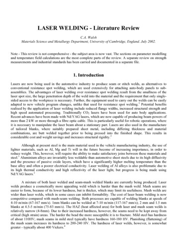
Ch01-P373588.tex1/2/200711: 36Page 19H E AT C O N D U CT I O N1 / 19where B is the thickness of the material and k is its thermal conductivity. Comparison with Equation(1.18) shows that the R-value is the thermal resistance, in English units, of a slab of material havinga cross-sectional area of 1 ft2 . Since the R-value is always given for a specified thickness, the thermalconductivity of a material can be obtained from its R-value using Equation (1.26). Also, since R-valuesare essentially thermal resistances, they are additive for materials arranged in series.Example 1.7Triple-glazed windows like the one shown in the sketch below are often used in very cold climates. Calculate the R-value for the window shown. The thermal conductivity of air at normal roomtemperature is approximately 0.015 Btu/h · ft · F.0.08 in. thick glasspanes0.25 in. air gapsTriple-pane windowSolutionFrom Table A.3, the thermal conductivity of window glass is 0.78 W/m · K. Converting to Englishunits gives:kglass 0.78 0.57782 0.45 Btu/h · ft · FThe R-values for one pane of glass and one air gap are calculated from Equation (1.26):Rglass 0.08/12 0.01480.45Rair 0.25/12 1.38890.015The R-value for the window is obtained using the additive property for materials in series:R-value 3Rglass 2Rair 3 0.0148 2 1.3889R-value 2.81.5 The Conduction Shape FactorThe conduction shape factor is a device whereby analytical solutions to multi-dimensional heat conduction problems are cast into the form of one-dimensional solutions. Although quite restricted
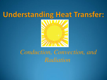
Ch01-P373588.tex1 / 201/2/200711: 36Page 20H E AT C O N D U CT I O NTable 1.3 Conduction Shape Factors (Source: Ref. [5])Case 1Isothermal sphere buried ina semi-infinite mediumT2ZT12πD1 D/4zz D/2S L DS L DS L D1 , D2L wS z D/2L zS 2πLln(8z/πD)w DL wS 2πLln(1.08 w/D)D dL DS DT2Case 2Horizontal isothermalcylinder of length L buriedin a semi-infinite mediumZ2πLcosh 1 (2z/D)LDT1Case 3Vertical cylinder in asemi-infinite mediumT2LT12πLln(4L/D)DCase 4Conduction between twocylinders of length L ininfinite mediumD1T1D22πL4w2 D12 D222D1 D1cosh 1T2WCase 5Horizontal circular cylinderof length L midway betweenparallel planes of equallength and infinite widthT2 T1ZDZ T1 T2Case 6Circular cylinder of length Lcentered in a square solidof equal lengthT2DwT1Case 7Eccentric circularcylinder of lengthL in a cylinder ofequal lengthT1dD T2zcosh 1 2πL D2 d 2 4z 22Dd(Continued)
Ch01-P373588.tex1/2/200711: 36Page 21H E AT C O N D U CT I O N1 / 21Table 1.3 (Continued)Case 8Conduction through the edgeof adjoining wallsT2LDD L/5S 0.54 DL length andwidth of wallS 0.15 LT1LCase 9Conduction through corner ofthree walls with a temperaturedifference T1 T2 acrossthe wallsLLLCase 10Disk of diameter D and T1 on asemi-finite medium of thermalconductivity k and T2S 2DDT1kT2Case 11Square channel of length LLT1T2W 1.4wW 1.4w2πL0.785 ln(W /w)2πLS 0.930 ln(W /w) 0.050S wWin scope, the shape factor method permits rapid and easy solution of multi-dimensional heattransfer problems when it is applicable. The conduction shape factor, S, is defined by therelation:q kS T(1.27)where T is a specified temperature difference. Notice that S has the dimension of length. Shapefactors for a number of geometrical configurations are given in Table 1.3. The solution of a probleminvolving one of these configurations is thus reduced to the calculation of S by the appropriateformula listed in the table.The thermal resistance corresponding to the shape factor can be found by comparing Equation(1.16) with Equation (1.27). The result is:Rth 1/kS(1.28)This is one of the thermal resistance formulas listed in Table 1.2. Since shape-factor problemsare inherently multi-dimensional, however, use of the thermal resistance concept in such cases
Ch01-P373588.tex1 / 221/2/200711: 36Page 22H E AT C O N D U CT I O Nwill, in general, yield only approximate solutions. Nevertheless, these solutions are usually entirelyadequate for process engineering calculations.Example 1.8An underground pipeline transporting hot oil has an outside diameter of 1 ft and its centerline is 2 ftbelow the surface of the earth. If the pipe wall is at 200 F and the earth’s surface is at 50 F, whatis the rate of heat loss per foot of pipe? Assume kearth 0.5 Btu/h · ft · F.Solution 50 F200 F2 ftoil1 ftFrom Table 1.3, the shape factor for a buried horizontal cylinder is:S 2πLcosh 1 (2 z/D)In this case, z 2 ft and r 0.5 ft. Taking L 1 ft we have:S 2πLcosh 1 (4) 3.045 ftq kearth S T 0.5 3.045 [200 ( 50)]q 380 Btu/h · ft of pipeNote: If necessary, the following mathematical identity can be used to evaluate cosh 1 (x):cosh 1 (x) ln x x2 1Example 1.9Suppose the pipeline of the previous example is covered with 1 in. of magnesia insulation(k 0.07 W/m · K). What is the rate of heat los
Heat conduction is one of the three basic modes of thermal energy transport (convection and radiation being the other two) and is involved in virtually all process heat-transfer operations. In commercial heat exchange equipment, for example,