Transcription
Οπτικά Δίκτυα ΕπικοινωνίαςOptical Network Architectures1
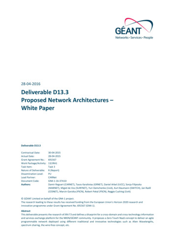
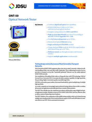
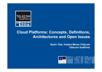
Overview of Optical NetworksThe network as a cloud of information flows connecting different participants: Network access toenterprises, governmentagencies, residentialcustomers, etc. Distances 100 m - 10 km High-capacity optical fiberlinks between cities and majorhubs (e.g. data centers) Distances between nodes:1000-10000 km Distances betweennodes 1000 kmThe Role of Optical NetworksOptical network segments are categorized with respect to the size of the area they cover: Long-haul core networks, also known as Wide Area Networks (WAN) orinterchange carrier (IXC) public networks. Edge/regional/metro networks, also known as Metropolitan Area Network (MAN) orlocal exchange carrier (LEC). Access networks providing peripheral links (“last-mile access”) to the end-users.2
Modulation Formats: Direct DetectionIntensity Modulation – Direct Detection (IM/DD) First optical networks relied only on simple On-Off Keying (OOK) binary formats with data rates of 1, 2.5, 4 and10 Gbit/s. Both Non-Return-to-Zero (NRZ) and Return-to-Zero (RZ) pulse shaping employed.Phase Modulation – Direct Detection (PM/DD) 3The next step was purely phase-modulated Differential Phase Shift Keying (DPSK) and DifferentialQuadrature Phase Shift Keying (DQPSK), directly detected using Delay-line Interferometers (DIs).DPSK has the same bandwidth efficiency as NRZ/RZ-PAM, but is more resistant to fiber transmission nonlinearities.DQPSK has (in addition) higher bandwidth efficiency (2 bits/symbol), and the rate could be increased withoutincreasing the bandwidth.DPSK and DQPSK transponders capable of 10 and 40 Gbit/s were commercialized, and still used today.
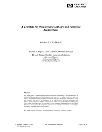
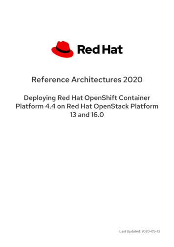
Modulation Formats: The Coherent RevolutionAdvanced Formats Using Coherent Optical Detection Coherent reception uses a 90 degree hybrid and local oscillator laser to analyze the receivedoptical signal into its In-Phase and Quadrature components: We can detect both Amplitude andPhase modulation at the same time. An IQ modulator is used to create advanced Quadrature Amplitude Modulation (QAM) formatswith higher bandwidth efficiency. Digital Signal Processing (DSP) is used to mitigate transmission impairments and detect thesymbols. While the concept is old (1990s), the processing power did not exist at the time, and coherentoptical systems were not possible: The advent of very high speed digital CMOS electronics inrecent years is what made the coherent revolution possible. The current commercial standard: 100 Gbit/s Dual-Polarization QPSK (DP-QPSK)QAM Transmitter4QAM Receiver
Modulation Formats: Historical Perspective andCurrent Deployment Telecom operators have deployed 100G (DP-QPSK) channels since 2010.The next step for commercial standardization is 400G optical channels, most probably employingDP-16-QAM (twice the bandwidth efficiency compared to 100G).Typical deployment scenarios for each segment in current optical networks:5 OOK (1, 2.5, 4, 10 Gbit/s) in Access and Metro. DPSK (10, 40 Gbit/s) and DQPSK (10, 40 Gbit/s) mostly in Metro, legacy equipment still present in Corenetworks. Coherent DP-QPSK (100 Gbit/s) mostly in the Core, with some system vendors providing lower-performance andlower-cost options targeted for Metro networks Future optical networks are expected to be all-coherent in the Metro and Core, using higher-order QAM (16-, 32-,64-QAM).
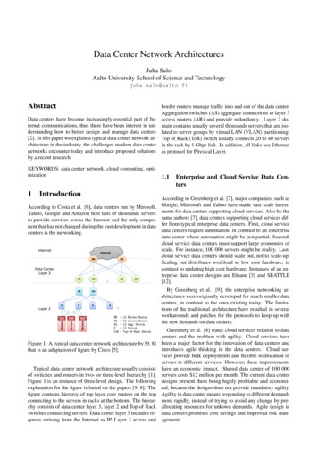
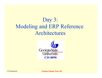
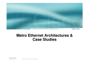
Network Topologies The physical network topology that best supports traffic demand generallyvaries with the segments (Core, Metro, Access) of the optical networkingstructure. End-to-end optical signal connections (point-to-point or broadcast) are calledlightpaths (or optical channels). A given connection is associated with Quality of Service (QoS)requirements (physical or network), which is then related to each individuallightpath.MeshStarRing6
Network TopologiesLightpaths differ in lengths and information capacity that is carried along.Typically: Core: 40-100 Gbit/s per optical wavelength, 1000 km Metro: 1-40 Gbit/s per optical wavelength, 1000 km Access: 1 Gbit/s per optical wavelength, 10 km7
1st Generation of Optical NetworksOptics for: Transmission (lower BER than copper links) CapacitySwitching and Network functions Electronics8
Towards to 2nd Generation: TDM and WDMComplementary methods of increasing fiber capacity: Time Division Multiplexing: Increase the serial bitrate. Wavelength Division Multiplexing: Increase the number of parallel wavelengths. High-speed, high-bandwidthelectronic equipment needed Expensive to build & maintain Send data in parallel, on thesame optical fiber Multiple wavelengths usinglower-rate electronic/opticalequipment to achieve higherthroughputs overall9
Wavelength Division MultiplexingWDM technology signaled a real start to optical networking:10 Each wavelength within the WDM spectrum could follow a distinct lightpath – enabledrouting of optical signals along the network paths. Amplification of the signals by using the stimulated emission principle. No optoelectronic conversion (O-E-O) needed. All-optical networks made possible. Possible to compensate chromatic dispersion by periodic deployment of special opticalfibers, called dispersion compensating fibers (DCF). Amplifiers and DCFs could handle multiple wavelengths together.
Wavelength Division Multiplexing11 Modern WDM optical networks rely onusing spans between nodes. These consist of 70-100 km lengthsof fiber, with amplifiers (EDFAs) andDCFs. Total transmission reach in this waycan be several thousand kilometers(with no O-E-O conversion needed). Easy upgrades: As more capacity isneeded, simply add more Txs and Rxson new wavelengths (low cost, existingtechnology with same bandwidth).
Wavelength Division MultiplexingThe result: WDM technology maturity and introduction of several complementarytechnologies enabled unprecedented growth in total transmission capacity, but also intransmission link length.12
Coarse WDMThe International Telecommunications Union (ITU) G.694.2 recommendation on CoarseWavelength Division Multiplexing (CWDM) for city and access networks:13 A fixed grid of 16 channels between 1270 nm and 1610 nm 20 nm spacing between channels ( 2500 GHz) Large channel spacing allows the use of cheap components (e.g. low cost lasers).A lot of bandwidth is wasted (a typical optical channel is 1-100 GHz).
Dense WDMITU G.694.1 recommendation on Dense Wavelength Division Multiplexing (DWDM): A fixed grid of 80 DWDM wavelengths over one pair of fiber DWDM channel spacing 0.8 nm (100 GHz grid) or 0.4 nm (50 GHz grid) Distances 1000 kms can be achieved with the use of optical amplifiers 14Denser packing of channels than CWDM, higher spectral efficiency.Higher cost.
Wavelength Division Multiplexing15 Based on optical power loss of fibers, spectrum ranges have been characterized forcompatibility purposes with light sources, receivers and optical components, includingthe optical fiber. According to the broad absorption minimum, the third window is best suited forDWDM technology. For DWDM transmission systems, three optical bands are defined: The Short Band (S-Band): 1460 to 1530 nm The Conventional Band (C-Band): 1530 to 1565 nm The Long Band (L-Band): 1565 to 1625 nm
Wavelength Division MultiplexingFixed CWDM & DWDM ITU grids16 CWDM is the cheaper alternative, traditionally used in Metro opticalnetwork applications (shorter distances, more links, more transceiversneeded). DWDM is used for long-distance Core optical networks (in addition toMetro), where higher-performing, more expensive (but fewer) transceiversare needed.
DWDM Vs CWDM Summary17Coarse WDMDense WDMLow-cost equipmentMore versatile (more expensive)Metro NetworksMetro and Core NetworksPoint-to-point (P2P) topologiesP2P, ring, meshUp to 16 channels with 20 nm spacing 80 channels with 50 GHz spacingUp to 80 km (20 dB attenuation)Reach of several 1000 kmNo optical amplificationOptical amplification with EDFAs possible10G wavelengths sometimes not supported100/400G channels supported
Basic Functional Blocks of a WDM Network (1/2)18 The transponder can receive an input optical signal and convert it into the electrical domain, andvice versa (uses optoelectronic modulators to convert electronic data into optical signals). The WDM multiplexer/demultiplexer (MUX/DEMUX) combines/separates discrete wavelengthsat the transmitter/receiver sides. Amplifiers (EDFAs, Raman) are used for pre- (Rx-side), post- (Tx-side), and in-line (in each fiberspan) amplification of the optical signals.
Basic Functional Blocks of a WDM Network (2/2)19 Reconfigurable Optical Add Drop Multiplexers (ROADMs) are key components of all-opticalnetworks. They perform optical routing by removing or inserting one or more wavelengths propagating alongthe fiber, without converting them into electrical signals. ROADMs are reconfigurable and dynamic multi-degree nodes, with single-wavelength granularity.
Access Optical Networks Access networks provide connectivity to the end-user customers (residential,commercial, government/public organizations, laboratories, wireless base stations,etc.).These include both wired (copper and optical), as well as wireless technologies: 20ADSL, VDSL, GSM, UMTS, LTE, WiFi, WiMAX, etc.Vast majority of wired access networks in Europe and the US are over copper (e.g.ADSL), while several Asian countries (United Arab Emirates, South Korea, HongKong, Japan) have high penetration (up to 85% for the UAE) of optical access.
Fiber to the x (FTTx) Last-mile optical networks are referred to as Fiber to the x (FTTx). For example:Fiber to the Node (FTTN)Fiber reaches a street cabinet several kilometers from the customers, with the final connections being copper.Often used in triple-play services (telephony, internet, TV).Fiber to the Curb (FTTC)Fiber reaches a street cabinet close to the customer ( 300m). Final connections may be high-bandwidth wiredEthernet or wireless (WiFi).Fiber to the Premises (FTTP) - also known as Fiber to the Home (FTTH) and Fiber to the Building (FTTB):Fiber reaches the boundary of the residential or commercial building. Passive optical networks (PONs) andpoint-to-point Ethernet are architectures that deliver triple-play services over FTTH networks directly from anoperator's central office. 21Two different architectures: Star (Passive Optical Networks) or Point-to-Point (Active Ethernet).
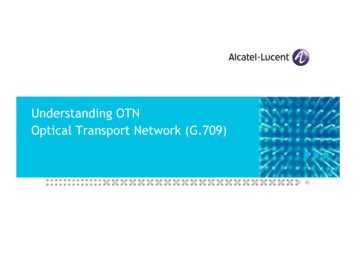
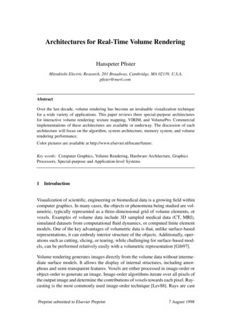
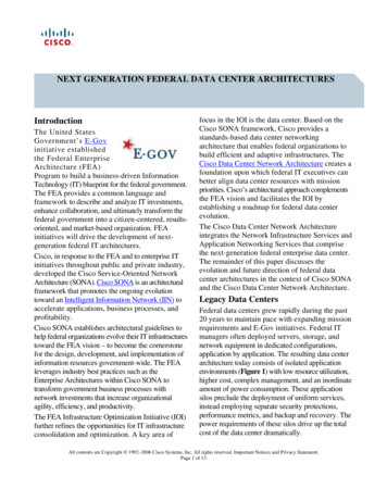
Star: Passive Optical Networks (PONs) The Optical Line Terminal (OLT) at the service provider’s central office (CO) broadcasts datato several Optical Network Terminals (ONTs) at the customer premises through the passivefiber network. All ONTs receive the same broadcast data, selecting the appropriate portion corresponding to theend-user it is serving.ABCD ABCD ABCD 22AB
Current Standards: TDM-PONsGigabit Passive Optical Network (GPON) TDM architecture, 2.5 Gbit/s downstream, 1.2 Gbit/s upstream Typically have multiple GPON ports per OLT card, with each card serving more than 100 customers. Single shared fiber: Fewer fibers than point‐point (if splitter deployed in the field). Splits: Up to 128, but typ. 32 or 64. Typical reach: 20km with 32 splits, but some vendors provide longer reach. Typical optical budget 28 dB, but higher budget optics available.XGPON and XGPON2 (also known as NGPON1)23 TDM architecture XG-PON is asymmetric: 10 Gbit/s downstream and 2.5 Gbit/s upstream XG-PON2 is symmetric: 10 Gbit/s downstream and 10 Gbit/s upstream
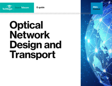
Point-to-Point: Active Ethernet24 Dedicated point-to-point connections for each ONT. 1 fiber per customer.
Current Standards: Active Ethernet 25“Future‐proof”: Upgrade individual users by changing electronics.User isolation: Dedicated connection & simpler traffic management.Potential for simpler and lower cost ONT.More fiber than GPON.the GPON splitter at the C.O. to proof their fiber installation.Reach: 20‐80 km depending on optics.
PON Vs Active EthernetActive Ethernet26TDM-PON (GPON, XGPON)Potential for higher capacity(limited only by TRx speed)Higher density ONT- More subscribers per platform- Lower power per subscriber- Lower cost per subscriberUser isolation (no “rogue” ONTscan steal data)Fewer fibers/cables in the centraloffice (and feeder/exchange)- More subscribers per fiber- Lower mean time to repair(MTTR)Simpler traffic managementPrevailing architecture for largetelecom providersPotential for lower complexity ONTEvolution to WDM-PON standards
Future Standards: TDM/WDM-PONWhy move to WDM‐PON? Combines good qualities of TDM and point-to-point: Effectively delivers point-to-pointperformance with fiber density comparable to TDM‐PON.32‐40 users per fiber, 1 user per wavelength. TDM-PON: 10G/32 users 312 Mbps/user over single fiber WDM-PON: 1 Gbps per wavelength 1 Gbps/user over single fiberHybrid approaches are also possible, such as an XGPON or GPON per wavelength.WDM-PON 27Pure WDMWavelength selection is done with an AWG,and only 1 wavelength reaches each ONTTDM/WDM-PON Both TDM and WDMPassive splitting, all wavelengths reach ONTsWavelength selection done at ONTs
Future Standards: NG-PON2NG-PON2 (currently being specified, expected in 2015) 2840 Gbit/s downstream, 10 Gbit/s upstreamSeveral options: WDM, Ultra-Dense WDM-PON (UDWDM), OFDM, TDM,TDM/WDM, Hybrid system with 4 x XGPON multiplexing.
The Future: Flexible Networks (1) Exponential Traffic Growth makes the traditional WDM schemes toreach its capacity and reach limits. Demands: Less rigid (‘Elastic’) Spectrum Specifications (channel spacing 50GHz AND 100 GHz) Variety of Modulation Formats (coherent QAM) and rates: 100G,400G, 1T, etc. Multicarrier transmission“Super-Channel” concept29
The Future: Flexible Networks (2) Flexible DWDM Grid (ITU-T G.694.1) – FlexGrid standard 12.5 GHz spectral granularity is able to support variable transmissionrates 100Gb/s30
The Future: Flexible Ne
Edge/regional/metro networks, also known as Metropolitan Area Network . Ethernet or wireless (WiFi). Fiber to the Premises (FTTP) - also known as Fiber to the Home (FTTH) and Fiber to the Building (FTTB): Fiber reaches the boundary of the residential or commercial building. Passive optical networks (PONs) and point-to-point Ethernet are architectures that deliver triple-play services over .