Transcription
TITAN PUMPS1
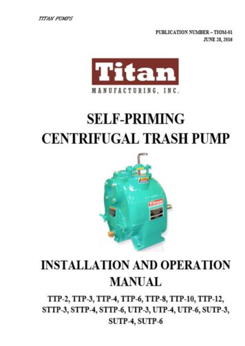
TITAN PUMPSINTRODUCTIONPlease read this manual carefully to learn how to safely install and operate your pump.Failure to do so could result in personal injury or damage to the pump.If there are any questions regarding the pump which are to covered in this manual or in otherliterature accompanying the unit, please contact at following Titan Pumps office:9447 Bamboo Rd.Houston, TX 77041.(713)-283-7700, (281) 817-5600 Tel.(713) 283-7600 Faxsales@titanpumpsinc.com2
TITAN PUMPSContentsINTRODUCTION2CONTENTS3RECORDING MODEL AND SERIAL NUMBERS4WARRANTY INFORMATION4SAFETY5INSTALLATION7POSITIONING PUMP8SUCTION LINES9DISCHARGE LINES11AUTOMATIC AIR RELEASE VALVE13ALIGNMENT15ELECTRICAL N20OPERATION20STOPPING22BEARING TEMPERATURE CHECK23LUBRICATION23WARRANTY TERMS26NOTES273
TITAN PUMPSRECORDING MODEL AND SERIAL NUMBERSPlease record the pump model and serial number in the spaces provided below. TitanManufacturing needs this information when you require parts or service.Pump Model:Serial Number:WARRANTY INFORMATIONThe warranty provided with your pump is part of the Titan Pumps program for customerswho operate and maintain their equipment as described in this and the other accompanyingliterature. Please note that should the equipment be abused or modified to change itsperformance beyond the original factory specifications, the warranty will become void andany claim will be denied.The following are used to alert personnel to procedures which require special attention, tothose which could damage equipment and to those which could be dangerous to personnel:Immediate hazards which WILL result in severe personal injury or death. Theseinstructions describe the procedure required and the injury which would result fromfailure to follow the procedure.W!!!WARNING!!C!!!CAUTION!!4
TITAN PUMPSSAFETYW!!!This information applies to Titan Self-Priming Centrifugal pumps. These pumps are availableas basic models driven by an electric motor, gasoline or diesel engine. Refer to the manualaccompanying the power source before attempting to begin operation. This manual will alertpersonnel to known procedures which require special attention, to those which could damageequipment, and to those which could be dangerous to personnel. However, this manualcannot possibly anticipate and provide detailed instructions and precautions for everysituation that might occur during maintenance of the unit. Therefore, it is the responsibility ofthe owner/maintenance personnel to ensure that only safe, established maintenanceprocedures are used and that any procedures not addressed in this manual are performed onlyafter establishing that neither personal safety nor pump integrity are compromised by suchpractices.Before attempting to open or service the pump:1. Familiarize yourself with this manual.2. Disconnect or shut down the power source and take necessary precautions to ensurethat the pump will remain inoperative.3. Allow the pump to completely cool if overheated.4. Close the suction and discharge valves.5. Vent the pump slowly and cautiously.6. Drain the pump.Do not attempt to pump any liquids the pump has not been designed for and which maydamage the pump or endanger personnel as a result of pump failure. Consult the factory todetermine compatibility between the pump and liquid.W!!!W!!!W!!!W!!!W!!!Use lifting and moving equipment in good repair and with adequate capacity to preventinjuries to personnel or damage to equipment. Suction and discharge hoses and piping mustbe removed from the pump before lifting.After the pump has been positioned, make certain that the pump and all piping or hoseconnections are tight, properly supported and secure before operation.Do not operate the pump against a closed discharge valve for long periods of time. Ifoperated against a closed discharge valve, pump components will deteriorate, and the liquidcould come to a boil, build pressure and cause the pump casing to rupture or explode.Do not remove plates, covers, gauges, pipe plugs, or fittings from an overheated pump. Vaporpressure within the pump can cause parts to disengaged and be ejected with great force.Allow the pump to cool before servicing.5
TITAN PUMPSW!!!These pumps may be used to handle products which if overheated could produce dangerousfumes. Use extreme caution when venting the pump, or when removing covers, plates, plugs,or fittings.W!!!Never run this pump backwards. Be certain that rotation is correct before fully engaging thepump.W!!!If the pump is used to pump materials which could cause serious illness or injury throughdirect exposure or emitted fumes, wear protective clothing, such as rubber gloves, facemaskand rubber apron as necessary before disassembling the pump or piping.W!!!Do not operate the pump without shields and/or guards in place over the drive shafts, belts,and/or couplings. Exposed rotating parts can catchClothing, fingers, or tools, causing severe injury to personnel.W!!!W!!!If the pump is powered by an electric motor; do not operate a non-explosion proof motor inan explosive atmosphere. An explosion, which may cause severe personal injury or death,could result. Install, connect and operate the motor in accordance with the National ElectricCode and all local codes. If there is a conflict between the instructions in the manualaccompanying the unit and the National Electric Code or applicable local code, the Nationalor Local code shall take precedence. All electrical equipment supplied with the pumpconforms to applicable federal regulations and national codes in effect on the date ofmanufacture.If the pump is electric motor driven, the electrical power used to operate this pump is highenough to cause injury or death. Obtain the services of a qualified electrician to troubleshoot,test and/or service the electrical components of the pump.If the pump is powered by an internal combustion engine, do not operate in an explosiveatmosphere. When operating internal combustion engines in an enclosed area, make certainthat exhaust fumes are piped to the outside. These fumes contain carbon monoxide, a deadlygas that is colorless, tasteless, and odorless.W!!!Fuel used by internal combustion engines presents an extreme explosion and fire hazard.Make certain that all fuel lines are securely connected and free of leaks. Never refuel a hot orrunning engine. Avoid overfilling the fuel tank. Always use the correct type of fuel.W!!!Never tamper with the engine governor to gain more power. The governor establishes safeoperating limits that should not be exceeded. The maximum continuous operating speed forthe pump is shown on the performance curve.W!!!If the pump is powered by an engine, the engine exhaust from this product contains chemicalsknown to cause cancer, birth defects and other reproductive complications.6
TITAN PUMPSINSTALLATIONReview all SAFETY information FIRST.Since pump installations are seldom identical, this section offers only generalrecommendations and practices required to inspect, position and arrange the pump andpiping. Most of the information pertains to a standard static lift application where the pump ispositioned above the free level of liquid to be pumped. If installed in a flooded suctionapplication where the liquid is supplied to the pump under pressure, some of the informationsuch as mounting, line configuration and priming must be tailored to the specific application.Since the pressure supplied to the pump is critical to performance and safety, be sure to limitthe incoming pressure to 50% of the maximum permissible operating pressure as shown onthe pump performance curve.For further assistance, contact Titan Manufacturing.PRE-INSTALLATION INSPECTIONThe pump assembly was inspected and tested before shipment from the factory.Before installation, inspect the pump for damage which may have occurred during shipment.Check as follows:a. Inspect the pump and power source (if so equipped) for cracks, dents, damagedthreads, etc. and obvious damage.b. Check for and tighten any loose hardware. Since gaskets tend to shrink after drying,check for loose hardware at mating surfaces.c. Carefully read all tags and note pump shaft rotation.d. Check levels and lubricate as necessary. Refer to LUBRICATION in theMAINTENANCE AND REPAIR section of this manual and any other literatureaccompanying the unit and perform duties as instructed.e. If the pump and power source have been stored for more than 12 months, or if themaximum shelf life has been exceeded, contact Titan Manufacturing to determine therepair or updating policy. Do not put the pump into service until appropriate actionhas been taken.Battery InstallationIf the pump is engine driven, the engine battery is not included with the unit unless otherwisespecified on the pump order. See the battery tag included with the battery box assemblyspecifications.7
TITAN PUMPSPOSITIONING PUMPLiftingUse lifting equipment with a capacity of at least 5 times the weight of the pump, notincluding the weight of accessories. Customer installed equipment such as suction anddischarge piping must be removed before lifting.The pump assembly can be seriously damaged if the chains or cables used to lift and movethe unit are improperly wrapped around the pump.MountingC!Level mounting is essential for proper operation. The pump may have to be supported orshimmed to provide for level operation or to eliminate vibration. If the pump has beenmounted on a moveable base, make certain the base is stationary by setting the brake andblocking the wheels before attempting to operate the pump. If the pump is engine driven, donot position the pump and engine more than 15 degrees off horizontal for continuousoperation in order to ensure sufficient lubrication and fuel supply to the engine. The pumpand engine may be positioned up to 30 degrees off horizontal for intermittent operation only;however, the engine manufacturer should be consulted for continuous operation at anglesgreater than 15 degrees.ClearanceWhen positioning the pump, allow clearance in front of the back cover to permit removal ofthe cover and easy access to the pump interior. Consult the factory or the Specification Datasheet for recommended clearance.SUCTION AND DISCHARGE PIPINGPump performance is adversely affected by increased suction lift and discharge elevation. Seethe performance curve to be sure your overall application allows the pump to operate withinthe safe operation range.MaterialsPipe or hose may be used for suction and discharge line however, the materials must becompatible with the liquid being pumped. If hose is used as the suction line it must be rigidwall reinforced to prevent collapse under suction. Using pipe couplings in suction lines is notrecommended.8
TITAN PUMPSLine ConfigurationKeep suction and discharge lines as straight as possible to minimize friction losses.Make minimum use of elbows and fittings, which substantially increase friction loss.If elbows are necessary, use the long-radius type to minimize friction loss.Connections to PumpBefore tightening a connecting flange, align it exactly with the pump port. Never pull a pipeline into place by tightening the flange bolts and/or couplings. Lines near the pump must beindependently supported to avoid strain on the pump which could cause excessive vibration,decreased bearing life, increased shaft and seal wear.If hose-type lines are used, they should have adequate support to secure them when filledwith liquid and under pressure.GaugesMost pumps are drilled and tapped for installing discharge pressure and vacuum suctiongauges. If these gauges are desired for pumps that are not tapped, drill and tap the suction anddischarge lines not less than 18 inches (457,2 mm) from the suction and discharge ports.Installation closer to the pump may result in erratic readings.SUCTION LINESTo avoid air pockets which could affect pump priming, the suction line must be as short anddirect as possible. When operation involves a suction lift, the line must always slope upwardto the pump from the source of the liquid being pumped. If the line slopes down to the pumpat any point along the suction run, air pockets will be created.FittingsSuction lines should be the same size as the pump inlet. If reducers are used in suction lines,they should be the eccentric type and should be installed with the flat part of the reducer up toavoid creating air pockets. Valves are not normally used in suction lines, but if a valve is usedinstall it with the stem horizontal to avoid air pockets.9
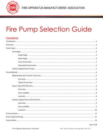
TITAN PUMPSStrainersIf a strainer is furnished with the pump, be certain to use it. If not furnished with the pumpbut is installed by the pump user, make certain that the total area of the openings in thestrainer is at least three or four times the cross section of the suction line and that theopenings will not permit passage of solids larger than the solids handling capability of thepump. Refer to the Specification Data sheet for the solids handling capability of your specificpump model.SealingSince even a slight leak will affect priming, head and capacity especially when operating witha high suction lift, all connections in the suction line should be sealed with pipe dope toensure an airtight seal. Follow the sealant manufacturer’s recommendations when selectingand applying the pipe dope, it should be compatible with the liquid being pumped.Suction Lines in SumpsIf a single suction line is installed in a pump, it should be positioned away from the wall ofthe sump at a distance equal to 1-1/2 times the diameter of the suction line. If there is a liquidflow from an open pipe into the sump, the flow should be kept away from the suction inletbecause the inflow will carry air down into the sump and air entering the suction line willreduce pump efficiency. If it is necessary to position inflow close to the suction inlet, install abaffle between the inflow and the suction inlet at a distance 1-1/2 times the diameter of thesuction pipe. The baffle will allow entrained air to escape from the liquid before it is drawninto the suction inlet. If two suction lines are installed in a single sump, the flow paths mayinteract, reducing the efficiency of one or both pumps. To avoid this, position the suctioninlets so that they are separated by a distance equal to at least 3 times the diameter of thesuction pipe.Suction Line PositioningThe depth of submergence of the suction line is critical to efficient pump operation.Figure 1 shows recommended minimum submergence vs. velocity.NOTEThe pipe submergence required may be reduced by installing a standard pipe increaserfitting at the end of the suction line. The larger opening size will reduce the inlet velocity.Calculate the required submergence using the following formula based on the increasedopening size (area or diameter).10
TITAN PUMPSFigure 1. Recommended Minimum Suction Line Submergence vs. VelocityDISCHARGE LINESSiphoningDo not terminate the discharge line at a level lower than that of the liquid being pumpedunless a siphon breaker is used in the line. Otherwise a siphoning action causing damage tothe pump could result.ValvesC!If a throttling valve is desired in the discharge line, use a valve as large as the largest pipe tominimize friction losses. Never install a throttling valve in a suction line. A check valve inthe discharge line is normally recommended but not necessary in low discharge headapplications. With high discharge heads, it is recommended that a throttling valve and asystem check valve be installed in the discharge line to protect the pump from excessiveshock pressure and reverse rotation when it is stopped. If the application involves a highdischarge head, gradually close the discharge throttling valve before stopping the pump.11
TITAN PUMPSBypass LinesSelf-priming pumps are not air compressors. During the priming cycle, air from the suctionline must be vented to atmosphere on the discharge side. If the discharge line is open, this airwill be vented through the discharge. However, if a check valve has been installed in thedischarge line, the discharge side of the pump must be opened to atmospheric pressurethrough a bypass line installed between the pump discharge and the check valve. A selfpriming centrifugal pump will not prime if there is sufficient static liquid head to hold thedischarge check valve closed.NOTEThe bypass line should be sized so that it does not affect pump discharge capacity; however,the bypass line should be at least 1 inch in diameter to minimize the chance of plugging.C!In low discharge head applications (less than 30 feet or 9 meters), it is recommended thatthe bypass line be run back to the wet well and located 6 inches below the water level or cutoff point of the low level pump. In some installations, this bypass line may be terminatedwith a six-to-eight foot length of 1 1/4 inch I.D. smooth-bore hose; air and liquid ventedduring the priming process will then agitate the hose and break up any solids, grease, or besecured against being drawn into the pump suction inlet. It is also recommended that pipeunions be installed at each 90 elbow in a bypass line to ease disassembly and maintenance.In high discharge head applications (more than 30 feet), an excessive amount of liquid maybe bypassed and forced back to the wet well under the full working pressure of the pump, thiswill reduce overall pumping efficiency. Therefore, it is recommended that an Automatic AirRelease Valve be installed in the bypass line. Automatic Air Release Valves are reliable andfor installation and operation of the Automatic Air Release Valve. Consult TitanManufacturing for selection of an Automatic Air Release Valve to fit your application. If theinstallation involves a flooded suction such as a below ground lift station, a pipe union andmanual shut-off valve may be installed in the bleed line to allow service of the valve withoutshutting down the station, and to eliminate the possibility of flooding. If a manual shut-offvalve is installed anywhere in the air release piping, it must be a full-opening ball type valveto prevent plugging by solids.12
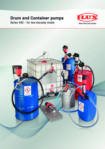
TITAN PUMPSW!!If a manual shut-off valve is installed in a bypass line, it must not be left closed duringoperation. A closed manual shutoff valve may cause a pump which has lost prime tocontinue to operate without reaching prime, causing dangerous overheating andpossible explosive rupture of the pump casing. Personnel could be severely injured.Allow an over-heated pump to cool before servicing. Do not remove plates, covers,gauges, or fittings from an overheated pump. Liquid within the pump can reach boilingtemperatures and vapor pressure within the pump can cause parts being disengagedand ejected with great force. After the pump cools, drain the liquid from the pump byremoving the casing drain plug. Use caution when removing the plug to prevent injuryto personnel from hot liquid.AUTOMATIC AIR RELEASE VALVEWhen properly installed and correctly adjusted to the specific hydraulic operating conditionsof the application, the Automatic Air Release Valve will permit air to escape through thebypass line and then close automatically when the pump is fully primed and pumping at fullcapacity.Theory of OperationFigures 2 and 3 show a cross-sectional view of the Automatic Air Release Valve, and acorresponding description of operation.Figure 2. Valve in Open PositionDuring the priming cycle, air from the pump casing flows through the bypass line, and passesthrough the Air Release Valve to the wet well (Figure 2).13
TITAN PUMPSFigure 3. Valve in Closed PositionWhen the pump is fully primed, pressure resulting from flow against the valve diaphragmcompresses the spring and closes the valve (Figure 3). The valve will remain closed, reducingthe bypass of liquid 1 to 5 gallons (3.8 to 19 liters) per minute, until the pump loses its primeor stops.W!!Some leakage (1 to 5 gallons or 3.8 to 19 liters per minute) will occur when the valve isfully closed. Be sure the bypass line is directed back to the wet well or tank to preventhazardous spills.When the pump shuts down, the spring returns the diaphragm to its original position. Anysolids that may have accumulated in the diaphragm chamber settle to the bottom and areflushed out during the next priming cycle.NOTEThe valve will remain open if the pump does not reach its designed capacity or head. Valveclosing pressure is dependent upon the discharge head of the pump at full capacity. Therange of the valve closing pressure is established by the tension rate of the spring as orderedfrom the factory. Valve closing pressure can be further adjusted to the exact systemrequirements by moving the spring retaining pin up or down the plunger rod to increase ordecrease tension on the spring. Contact Titan Pumps for information about an Automatic AirRelease Valve for your specific application.Air Release Valve InstallationThe Automatic Air Release Valve must independently mounted in a horizontal position andconnected to the discharge line of the self-priming centrifugal pump (seeFigure 4).NOTEIf the Air Release Valve is to be installed on a staged pump application, contact the factoryfor specific installation instructions14
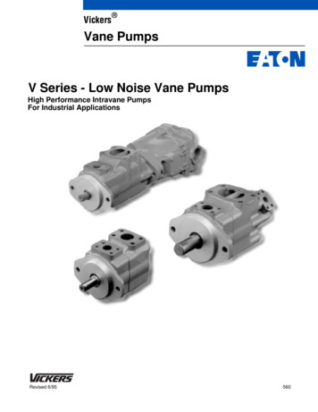
TITAN PUMPSFigure 4. Typical Automatic Air Release Valve InstallationThe valve inlet line must be installed between the pump discharge port and the nonpressurized side of the discharge check valve. The valve inlet is at the large end of the valvebody, and is provided with standard 1-inch NPT pipe threads.The valve outlet is located at the opposite end of the valve, and is also equipped with standard1-inch NPT pipe threads. The outlet should be connected to a bleed line which slopes back tothe wet well or sump. The bleed line must be the same size as the inlet piping or larger. Ifpiping is used for the bleed line, avoid the use of elbows whenever possible.NOTEIt is recommended that each Air Release Valve be fitted with an independent bleeder linedirected back to the wet well. If multiple Air Release Valves are installed in a system, theymust be fitted with independent bleeder lines; never use a common manifold pipe. ContactTitan Pumps for information about installation of an Automatic Air Release Valve for yourspecific applicationALIGNMENTThe alignment of the pump and its power source is critical for trouble-free mechanicaloperation. In either a flexible coupling or V-belt driven system, the driver and pump must bemounted so that their shafts are aligned with and parallel to each other. It is imperative thatalignment be checked after the pump and piping are installed, and before operation.15
TITAN PUMPSNOTECheck Rotation, Section C, before final alignment of the pumpWhen mounted at the factory, driver and pump are aligned before shipment. Misalignmentwill occur in transit and handling. Pumps must be checked and realigned before operation.Before checking alignment, tighten the foundation bolts, the pump casing feet and/or pedestalfeet. The driver mounting bolts should also be tightly secured.W!!C!When checking alignment, disconnect the power source to ensure that the pump willremain inoperative.Adjusting the alignment in one direction may alter the alignment in another direction.Check each procedure after altering alignment.Coupled DrivesWhen using couplings, the axis of the power source must be aligned to the axis of the pumpshaft in both the horizontal and vertical planes. Most couplings require a specific gap orclearance between the driving and the driven shafts. Refer to the coupling manufacturer’sservice literature.Align spider insert type couplings by using calipers to measure the dimensions on thecircumference of the outer ends of the coupling hub every 90 degrees. The coupling is inalignment when the hub ends are the same distance apart at all points (see Figure 5).Figure 5. Aligning Spider-Type Couplings16
TITAN PUMPSAlign non-spider type couplings by using a feeler gauge or taper gauge between the couplingshalves every 90 degrees. The coupling is in alignment when the hubs are the same distanceapart at all points (see Figure 6).Figure 6. Aligning Non-Spider Type CouplingsCheck parallel adjustment by laying a straightedge across both coupling rims at the top,bottom, and side. When the straightedge rests evenly on both halves of the coupling, thecoupling is in horizontal parallel alignment. If the coupling is misaligned, use a feeler gaugebetween the coupling and the straightedge to measure the amount of misalignment.V-Belt DrivesWhen using V-belt drives, the power source and the pump must be parallel. Use astraightedge along the sides of the pulleys to ensure that the pulleys are properly aligned (seeFigure 7). In drive systems using two or more belts, make certain that the belts are a matchedset; unmatched sets will cause accelerated belt wear.MISALIGNED:SHAFTSNOT PARALLELMISALIGNED:SHAFTSNOT IN LINEALIGNED: SHAFTSPARALLEL ANDSHEAVES IN LINEFigure 7. Alignment of V-Belt Driven PumpsTighten the belts in accordance with the belt manufacturer’s instructions. If the belts are tooloose, they will slip; if the belts are too tight, there will be excessive power loss and possiblebearing failure. Select pulleys that will match the proper speed ratio; over speeding the pumpmay damage both pump and power source.17
TITAN PUMPSnot operate the pump without the guard in place over the rotating parts. ExposedW!!! Dorotating parts can catch clothing, fingers, or tools, causing severe injury to personnel.ELECTRICAL CONNECTIONSIf the pump is driven by an electric motor, check that the electrical service available matchesthe motor requirements stamped on the motor nameplate before connecting a motor to theincoming power. Check that the motor speed meets pump specifications. If rotation isincorrect on a three-phase motor, have a qualified electrician interchange any two of the threephase wires to change direction. If rotation is incorrect on a single-phase motor, consult theliterature supplied with the motor for specific instructions.W!!!The electrical power used to operate the pump is high enough to cause injury or death.Obtain the services of a qualified electrician to make all electrical connections.W!!!If the pump is powered by an electric motor, do not operate a non-explosion proofmotor in an explosive atmosphere. An explosion, which may cause severe personalinjury or death, could result. Install, connect and operate the motor in accordance withthe National Electric Code and all local codes. If there is a conflict between theinstructions in the manual accompanying the unit and the National Electric Code orapplicable local code, the National or Local code shall take precedence. All electricalequipment supplied with the pump conforms to applicable federal regulations andnational codes in effect on the date of manufacture.18
TITAN PUMPSOPERATIONReview all SAFETY information FIRST.Follow the instructions on all tags, labels and decals attached to the pump.W!!Do not attempt to pump any liquids the pump has not been designed for and which maydamage the pump or endanger personnel as a result of pump failure.Pump speed and operating conditions must be within the performance range shown on theC! curve. Refer to the pump Data Sheet for the specific performance for your pump.PRIMINGInstall the pump and piping as described in INSTALLATION. Make sure that the pipingconnections are tight, and that the pump is securely mounted. Check that the pump isproperly lubricated (see LUBRICATION in the manual).C!The pump is self-priming, but it should never be operated unless there is liquid in the pumpcasing. The pump will not prime when dry. Extended operation of a dry pump will destroythe seal assembly.Add liquid to the pump casing when:1. The pump is being put into service for the first time.2. The pump has not been used for a considerable length of time.3. The liquid in the pump casing has evaporated.Once the pump casing has been filled, the pump will prime and reprime as necessary.W!!After filling the pump casing, reinstall and tighten the fill plug. Do not attempt tooperate the pump unless all connecting piping is securely installed. Otherwise, liquid inthe pump forced out under pressure could cause injury to personnel.To fill the pump, remove the pump casing, fill cover or full plug in the top of the casing andadd clean liquid until the casing is filled. Replace the fill cover or fill plug before operatingthe pump.STARTINGStarting procedures will vary slightly depending on the pump application, type of primingdevice and type of drive. Consult the operations manual furnished with the power source.19
TITAN PUMPSROTATIONC!The pump must operate in the direction indicated by the arrow on the pump, oraccompanying decals. Reverse rotation could loosen the impeller and seriously damage thepump. If the pump is driven by an electric motor, consult the operating manual furnished withthe motor before attempting to start the motor.If rotation is incorrect on a three-phase motor, have a qualified electrician interchange anytwo of the three phase wires to change direction.If rotation is incorrect on a single-phase motor, consult the literature supplied with the motorfor specific instructions.OPERATIONPump speed and operating points must be within the continuous performance range shown onthe pump curve. (See the Parts List accompanying the pump.)C!Lines with a BypassClose the discharge throttling valve (if so equipped) so that the pump will not have to primeagainst the weight of the liquid in the discharge line. Air from the suction line will bedischarged through the bypass line back to the wet well during the priming cycle. When thepump is fully primed and liquid is flowing steadily from the bypass line, open the dischargethrottling valve. Liquid will then continue to circulate through the bypass line while the pumpis in
Clothing, fingers, or tools, causing severe injury to personnel. If the pump is powered by an electric motor; do not operate a non-explosion proof motor in an explosive atmosphere. An explosion, which may cause severe personal injury or death, could result. Install, connect and o