Transcription
AUTODESK AUTOCAD CIVIL 2009 AND AUTOCAD CIVIL 3D 2009Road Design Basics withAutoCAD Civil and Civil 3D
ContentsIntroduction .3The Corridor Model .3The Assembly .4Subassemblies .5Leveraging Point, Link, and Shape Codes .6Leveraging Targets .7Superelevation .8Conclusion. 10Appendix . 11AutoCAD Civil 2009 and AutoCAD Civil 3D 2009 Subassembly Tables . 12Highway Design (New Construction): Lanes . 12Highway Design (New Construction): Medians . 13Highway Design (New Construction): Shoulders . 14Highway Design (New Construction): Bridge and Rail . 14Highway Design (New Construction): Daylight. 15Highway Design (New Construction): Channels and Retaining Walls. 16Road Rehab and Widening . 17Urban Design . 19Generic Links and Marked Points . 20Subassembly Functionality References . 22Subassembly Catalog Section References . 22
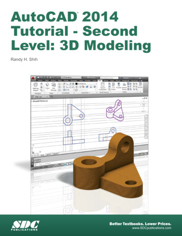
ROAD DESIGN BASICS WITH AUTOCAD CIVIL 2009 AND AUTOCAD CIVIL 3D 2009IntroductionThe Autodesk civil engineering solution, made up of AutoCAD Civil 2009 software and AutoCAD Civil 3D 2009software, provides civil engineers, designers, drafters, technicians, and surveyors with targeted solutions for a broadrange of project types, including land development, transportation, and environmental.The goal of this document is to outline the fundamentals of road design through corridors while focusing on thebehavior and function of assemblies and subassemblies. This paper explores the definitions and terminologiesbehind points, links and shapes— essential components for corridor modeling—and also addresses howsubassemblies have the capability to respond to superelevation parameters when modeling complex transportationprojects. Lastly, AutoCAD Civil 2009 software and AutoCAD Civil 3D 2009 software ships with a comprehensivecatalog of various assemblies that can be used for a multitude of project types including road rehabilitation, highwaydesign, local roads, and channels. This subassembly catalog has been condensed and added as a referenceappendix to allow for easier exploration while highlighting the functions of each subassembly and providing commonuses.The Corridor ModelCorridors are arguably the most powerful and sophisticated objects in AutoCAD Civil 2009 and AutoCAD Civil 3D2009. To create a corridor, an alignment, profile, and assembly are combined to form a 3-dimensional representationof a linear feature such as a road or channel. In this document, the focus will be on utilizing corridor models for roaddesign exclusively.Together the alignment and profile create a 3D Chain (Figure 1) with the alignment providing the horizontal aspect (xand y) and the profile providing the vertical aspect (z/elevation). The assembly, which represents the cross-sectionalshape of the road, is inserted along this 3D path at user-specified increments. Similar points on the assemblyinsertions are connected using corridor feature lines—establishing the edges of the 3D model in the longitudinaldirection.Figure 1. A 3D Chain represents an alignment and profile which control the horizontal and vertical aspects of the road. Anassembly is then inserted along this path at user-defined increments and is connected longitudinally by corridorfeature lines.The corridor model serves as the “backbone” of the design and from it many useful forms of information can bederived. For example, surfaces can be derived from the corridor representing finished ground or any number ofunderlying surfaces. The corridor can be shown in cross section views and earthwork and material volumes can be3
ROAD DESIGN BASICS WITH AUTOCAD CIVIL 2009 AND AUTOCAD CIVIL 3D 2009calculated. And, as shown in the image above, the corridor can be viewed from a 3D perspective giving the designera clearer sense of its construction when compared to a model that is purely numerical.For any road design you begin by defining the main alignment which is typically the centerline of the road. Then yousample existing ground surface information to create a profile of the current conditions of the road centerline. Thisprofile is then redesigned to create a smooth vertical path consisting of straight tangents and vertical curves. Theresulting geometry is the design profile and at this point you have two of the three components needed to build thecorridor.Next you build one or more assemblies that match the information shown in the typical sections for the road design.The assemblies simulate the geometry and material composition of the road as well as how it should interact withexisting ground, legal boundaries, and many other potential features. This interaction is automated by thesubassemblies allowing slopes to change, lanes to widen, and many other variations to take place as the corridorprogresses along its path.With the three components in place you then build the corridor and assign targets to ensure that any subassembliesthat interact with other drawing objects are seeking out the correct data. With this portion complete, you now have a3D model of the road design from which you can create surfaces, generate cross-section views, calculate materialvolumes, and many other design tasks.The AssemblyAs stated above, the assembly (Figure 2) is one of a trio of objects that comprises the corridor model. It representsthe cross-sectional composition of the road including the individual components such as curbs, lanes, and shoulders.These individual components are represented by subassemblies, which represent customizable cross-sectionalcomponents that are pieced together to create assemblies.Figure 2. An assembly is made of up a combination of subassemblies such as sidewalks, curb, and lanes.The assembly itself is actually a rather simple object, being a collection of subassemblies attached to a baseline. Thebaseline contains a baseline point, which is the location where the assembly will attach to the alignment-profile pair.To construct an assembly, you simply “snap” the pieces together by accessing a subassembly from a tool palette andclicking an attachment point on the assembly baseline, or on another subassembly. In this way, the completecomposition of the road cross section can be represented from median to lanes to curbs to daylight and a designercan simulate a wide range of road components and behaviors.For example, to create an assembly for a divided highway, you begin at the baseline point and simply insert theappropriate subassemblies such as a depressed median or a jersey barrier. Then, working outward, you insertsubassemblies for the inside lane, outside lane, shoulder, and daylighting. As each subassembly is inserted, you canmodify the input parameters to match the dimensions of the typical section of the proposed highway. In a short time,you have a fully functional assembly that represents the cross-sectional geometry and composition of the design.For a more complex design, like an intersection, the assemblies become key parts of the model rather than the entireroad cross section. In intersection design, it is common to create assemblies that represent only half of the crosssection (i.e. left lane, shoulder, and daylight). In this way, each portion of the intersecting roads can be controlledindependently to easily resolve the complex geometry often associated with intersections.4
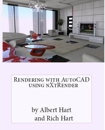
ROAD DESIGN BASICS WITH AUTOCAD CIVIL 2009 AND AUTOCAD CIVIL 3D 2009SubassembliesThe power and flexibility of the assembly actually resides within the subassemblies. AutoCAD Civil 2009 andAutoCAD Civil 3D 2009 provide an extensive collection of subassemblies for a wide variety of road designapplications. The scope of theirapplication ranges from very specific tovery general and their functionalityranges from very sophisticated to verysimple. In addition to the onesprovided, custom subassemblies canbe created from user-defined AutoCADshapes or through programming.Subassemblies can be “snapped”together in thousands of combinationsto model virtually any road designscenario.Figure 3. Subassemblies are made up of points, links and shapes. StylesThe fundamental components ofcan be assigned to each component, providing users with full control oversubassemblies are points, links, anddisplay and labeling characteristics of the subassembly.shapes. (Figure 3). Points are connectedby links, and when three or more links enclose an area, a shape is created. Codes and styles can be assigned to allthree of these types of components to control how the corridor is constructed, affect the appearance and behavior ofthe corridor, automate annotation, and simplify the extraction of data.The geometry and behavior of subassemblies is controlled by input parameters. For example, for many of the lanesubassemblies, there is a parameter called Width which controls the width of the lane.Figure 4. Input parameters allow specific components within subassemblies to be customized to fit specific projectrequirements. The example shown will create a lane 12’ wide with a cross slope of 2% and a material course depth of 0.67feet for the duration of the road.Other input parameters include the depth for each pavement course or the slope across the lane (Figure 4). Thesources of the values for these parameters vary depending on the intended function of the subassembly. Some aremanually entered by the user while others are derived automatically from another source of information within thedrawing. For example, the Width parameter mentioned above can be manually entered or have its valueautomatically derived from an alignment representing the outer edge of the travel way. In this case, the use of thealignment is established through a target parameter. This ability of subassemblies to interact with other objects in thedrawing and derive values automatically greatly increases the power of the corridor model.Subassemblies can also be tied to the superelevation parameters of the alignment. For example, as the corridor isbuilt, any subassemblies that reference superelevation information will recognize the information contained in thealignment and respond to it. For example, lanes will automatically adjust their cross-slopes through transition and fullsuperelevation.5
ROAD DESIGN BASICS WITH AUTOCAD CIVIL 2009 AND AUTOCAD CIVIL 3D 2009Leveraging Point, Link, and Shape CodesPoint, link, and shape codes—properties of a subassembly—can be used for amultitude of applications. Possibly the most important properties are point codes,as they control the creation of corridor feature lines that form the longitudinaledges of the corridor model. For example, the BasicLane subassembly assigns acode of ETW to the outer top corner (Figure 5). When the corridoris built, AutoCAD Civil 3D 2009 recognizes the matching codesbetween two adjacent subassemblies and draws a corridor featureline that connects them. In addition, the style that is applied to thecorridor feature line can be defined by this code and automaticallyassigned. The result is shown in Figure 6 below. Note how theFigure 5. In the example above, P2 represents acorridor feature line created by AutoCAD Civil 3D automaticallypoint on the subassembly that has the name ETW(edge of travel way) assigned to it.connects the points coded ETW.Note also how the style of the corridor feature line has beenassigned in Corridor Properties based on this code. (Figure 7)Figure 6. Corridor feature lines will automaticallyconnect ETW points as the corridor is created.Figure 7. Each feature line can be assigned a styleto control the display, for that part of the corridor.Codes, specifically link codes, are also a powerful tool forextracting data from the corridor model including contours, crosssections, or surfaces. In the example shown in Figure 8, the Topcode is used to filter out all links representing the finished groundelement of each subassembly. With this approach, a corridorsurface for the finished ground can be created in a matter ofseconds. A similar approach can be used to generate corridorsurfaces representing subsurface materials or portions of thecorridor. Codes can be used to perform functions such ascalculating material volumes or performing a mass haul analysis.Codes can also be leveraged to help save considerable time byautomating the annotation of corridor information. In the exampleshown in Figure 9, the Top Curb code was used to automaticallyprovide a label in all section views showing the offset and elevationof the top of curb.Figure 8. Codes can also be used when creatingor extracting data from the corridor model. Thisexample shows a finished grade surface readingthe Top codes to create contours from the model.6
ROAD DESIGN BASICS WITH AUTOCAD CIVIL 2009 AND AUTOCAD CIVIL 3D 2009Figure 9. This example shows Top Curb codes being used to labelcross sections. Offsets and elevations are automatically derivedfrom the corridor model and conform to company or jurisdictionalCAD standards.Figure 10. Code set styles can be setup toautomatically label specific points such as flow line,top of curb, crown, etc.With this capability, you can integrate codes, labels, and styles so that your design is labeled automatically with thecontent and formatting required by your company standards, a client’s standards or a given local jurisdiction (Figure10).AutoCAD Civil 3D 2009 software manages all of the codes that can be associated with a corridor through the use of acode set. Within the code set, the codes are organized by type (link, point, and shape).Figure 11. In addition to being used for automatically labeling cross sections and plan sets, code set styles can be easilyconfigured for visualization purposes.Each code can be assigned a label style to create the effect discussed above. In addition, each link code can beassigned a render material for visualization purposes and a material area fill for hatching within the drawing (Figure11). Each point code can be assigned a feature line style so that corridor feature lines can be matched up with theirfunctions. For example, corridor feature lines passing through the Top Curb code shown above could be assigned astyle that displays them on the curb layer (Figure 6). Capitalizing on this potential for automation can greatly improvethe efficiency of displaying and documenting the road design throughout the design cycle.Leveraging TargetsMany AutoCAD Civil 3D 2009 subassemblieshave the ability to interact with other objects in thedrawing through target parameters. For instance,all daylighting subassemblies function through asurface target parameter. Their job is to seek outand intersect with a given surface according to theinstructions provided in the input parameters.Figure 12. Daylight subassemblies use a surface target parameter toseek out and intersect surfaces based on input parameters. Forexample, DaylightMaxWidth Subassembly analyzes whether a cut orfill situation exists, and then uses input parameters to tie into asurface.7
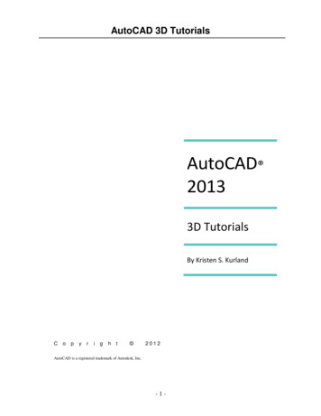
ROAD DESIGN BASICS WITH AUTOCAD CIVIL 2009 AND AUTOCAD CIVIL 3D 2009Many different daylighting scenarios can be modeled using the daylightsubassemblies provided with AutoCAD Civil 3D 2009. For example, theDaylightMaxWidth subassembly shown in Figure 12 will seek out a surfaceand tie to it while maintaining a given width for the daylight embankment.Other daylight subassemblies can automatically create benches, ditchesand berms, and/or adjust slope depending on the material being excavated.The table in the Appendix shows a complete list of the daylightingsubassemblies that are available and some of their more common uses.Figure 13. Unlike daylightingmethods, grading projections canclean up on each other and provideeasy solutions for complex designs.Daylighting can also be accomplished through feature lines and gradingprojections. Instead of using a daylight subassembly, it is possible to usethe grading creation tools in AutoCAD Civil 3D 2009 to project slopes froma corridor feature line. This can be especially advantageous when slope projections need to be perpendicular to afeature of the road rather than the centerline. It also allows you to take advantage of the ability of AutoCAD Civil 3Dgrading projections to “clean up” interior corners and interact with one another. Figure 13 shows how AutoCAD Civil3D can automatically calculate the solution between the corridor daylighting and the pond daylighting. This is madepossible through the use of gradingprojection from a feature line that isdynamically linked to the corridor.Part of the process of constructingthe corridor model is to assign theFigure 14. In order for a daylight subassembly to function properly, a target surfaceactual targets for subassemblies that is assigned within the corridor properties.utilize target parameters. As shownin the Figure 14, a target surface of EG has been assignedto the DaylightMaxWidth subassembly within the corridor.Other subassemblies utilize width or offset target parametersto change shape as they progress through the corridor. Aturning lane, for example, can be accomplished by using theBasicLaneTransition subassembly along with an alignmenttarget representing the edge of the travel way. As thealignment moves away from the road centerline, thesubassembly widens to create the additional lane. Figure 15shows the final result when this approach is used.Figure 15. Specific subassemblies can usealignments, profiles, polylines, feature lines, orsurvey figures as targets to control the shape of thecorridor.Slope or elevation targets can be utilized for some assemblies to control the vertical aspect of the corridor geometry.For instance, in the example show in Figure 15 a profile could be applied to the edge of the travel way to control itselevation at the same time the alignment is controlling its horizontal position. And finally, certain subassemblies cantarget a marked point, allowing them to seek out a specific location on another subassembly and connect to it.LinkBetweenPoints for instance, is often used in the area between a ramp and highway as the two merge. Thissubassembly will seek out a marked point on the ramp and automatically create a swale between the two roadways.SuperelevationMany subassemblies have the capability of responding to superelevation parameters. Superelevation is the bankingeffect of the road as it curves causing the edge to the outside of the curve to be higher in elevation than the inside.The superelevation parameters themselves are actually applied to the corridor baseline alignment and thesubassemblies that possess superelevation functionality derive the information from there (Figure 16).Superelevation parameters can be found by accessing the alignment properties and clicking the Superelevation tab.8
ROAD DESIGN BASICS WITH AUTOCAD CIVIL 2009 AND AUTOCAD CIVIL 3D 2009Figure 16. Superelevationparameters can be applied during thelayout of the horizontal alignment.Subassemblies can then use thesevalues as the superelevation is beingapplied throughout the design.The superelevation parameters consist of eight separate cross slope values that represent inside and outsideshoulders and lanes on both sides of the road. The values can be entered manually or calculated automaticallybased on AASHTO tables used by AutoCAD Civil 3D 2009 software. If your design does not apply AASHTO designstandards, you can use the Design Criteria Editor to create tables that meet nearly any design standard. Customtables can be saved, then shared throughout your organization and used on future projects.As AutoCAD Civil 3D 2009 builds the corridor, any subassemblies that possess superelevation functionality will readthese values and respond as needed. Civil 3D automatically calculates key stations such as end normal crown,reverse crown, and begin full super, and creates additional corridor sections at those locations to ensure accuratetransitioning. Figure 17 shows a corridor as it progresses through each key superelevation station.Figure 17. An example of superelevation being applied to a divided highway.As an example, Figure 18 shows how the LaneOutsideSuper subassembly uses the Outside Lane column to obtainits cross slope. The section view shows how, as the corridor enters superelevation transition, the outside edge of thesubassembly gradually tilts upward until it reaches full superelevation. It will maintain that configuration for aspecified distance and finally transition downward as the corridor passes beyond the curve.Figure 18. In the example above, the LaneOutsideSuper subassembly is using data from the Outside Lanecolumn, in the Alignment properties.9
ROAD DESIGN BASICS WITH AUTOCAD CIVIL 2009 AND AUTOCAD CIVIL 3D 2009ConclusionThe AutoCAD Civil 3D 2009 corridor model can make building, annotating, and analyzing your road design moreefficient—especially when all of the benefits of subassemblies are leveraged. This document has given you anoverview of the core components that AutoCAD Civil 2009 and AutoCAD Civil 3D 2009 use when modeling roads andhighlighted the fundamental building blocks required when piecing together assemblies and subassemblies. Bythoroughly understanding the subassemblies and their functions, you will be able to construct more effective corridormodels more efficiently. In addition, by leveraging points, links, shape codes and target parameters, you can createcorridor models that are tailored to your designs needs—while helping to automate many road design tasks such asautomatically labeling and updating cross sections.This paper has also exposed the capabilities of AutoCAD Civil 2009 and AutoCAD Civil 3D 2009 for transportationtype projects—identifying how subassemblies can respond to the banking effect of the road throughout the design.Superelevation is used all over the world on a multitude of project types and when used in conjunction with themodel-centric capabilities offered in the Autodesk Civil Engineering Solutions software, it provides engineers with avaluable resource for creating compelling designs for years to come.10
ROAD DESIGN BASICS WITH AUTOCAD CIVIL 2009 AND AUTOCAD CIVIL 3D 2009Appendix11
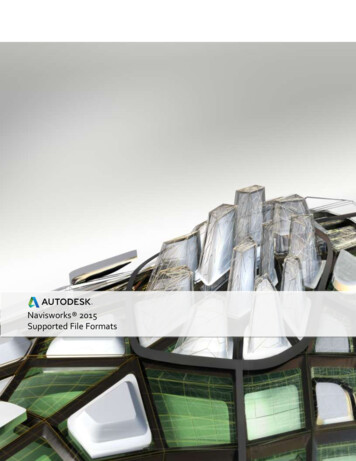
ROAD DESIGN BASICS WITHITH AUTOCAD CIVIL 2009 AND AUTOCAD CIVIL 3D 2009AutoCAD Civil 2009 and AutoCAD Civil 3D 2009 Subassembly TablesThe following tables can be used as a guide when selecting subassemblies for different types of design scenarios.Each subassembly is listed with a brief description and one or more common uses. The meaning of the codes in theRef column can be found at the end of the appendix. These codes refer to specific functionality possessed by eachsubassembly as well as where the subassemblies can be found in the AutoCAD Civil 3D 2009 catalog.Highway Design (New Construction): LanesImageNameDescriptionCrownedLaneA crowned lane with separate subbase slope Crowned road wherecontrol and the ability to control the location subgrade slope andof the subbase crown.crown needs to CSBA simple pavement structure with userdefinable point, link, and shape codes.Any pavementcourse.H,V,SEUDTD-LSU-LTwo travel lanes with independent crossslopes.Highways withmultiple lanes in onetravel ian1Maintains the cross slope of the lane whileextending it inward to create a left turn lane.Works in conjunction with an alignmentdefining the median edge.Medians with left imilar to LaneFromTaperedMedian1 except Medians with left turn H,V,that it allows for two lanes outside thelanes – multiple lanes SE,MCmedian.in one travel direction.direction on UsesRef:Lane that responds to Inside Lanesuperelevation value.Multi-lanelane roads withsuperelevation.superelevationH,V,SE,MCTD-LLane that responds to Inside Lanesuperelevation value and allows independentwidths for each pavement course. Up to 10different courses can be specified.Pavement structuresrequiring more thanfour courses withvarying widths.H,V,SE,MCTD-LSimilar to LaneInsideSuper except that there Pavement structuresrequiring more thanare additional available pavement courses.four courses.H,V,SE,MC,VSTD-LAll road lanes.lanesLaneOutsideSuperLane that responds to Outside Lanesuperelevation value. This subassembly iscommonly used for general-purpose rVaryingWidthLane that responds to Outside Lanesuperelevation value and allows independentwidths for each pavement course. Up to 10different courses can be specified.Pavement structuresrequiring more thanfour courses withvarying LayerVaryingWidthLaneInsideSuperMultiLayer12
ROAD DESIGN BASICS WITH AUTOCAD CIVIL 2009 AND AUTOCAD CIVIL 3D 2009Highway Design (New Construction): LanesLaneOutsideSuperMultiLayerSimilar to LaneOutsideSuper except thatthere are additional available pavementcourses.Pavement structuresrequiring more thanfour ngAutomatically widens lane in superelevatedHighways where lane H,V,regions using a formula based on the radius widening is requiredSE,MCTD-Lof the curve and the length of the wheelbase. when insuperelevation.LaneTowardCrownCreates a lane that slopes downward fromthe crown to the centerline by applying thenegative of the outside lane superelevationvalue from the opposite side of the road.Multi-lane roads withsuperelevation.H,V,SE,MCTD-LGeneric shape with user-defined geometryand codes.Irregular-shapedpavement coursesand other structures.H,V,VS,SE,UDTD-LSU-LDescriptionCommon UsesRef:Flush median with independent left and rightjersey barriers and subsurface courses thatcan be set to match the structure of abuttinglanes.Divided roads orhighways whereasymmetrical barriersare needed.H,V,SE,E,VSTD-MSU-MDepressed median between an attachmentpoint and marked point with variousparameters to control ditch geometry.Divided roads orhighways requiring adepressed median.TD-MSU-MDepressed Median with various options forsuperelevation rotation and subgradeextension.Divided roads orhighways requiring adepressed imilar to MedianDepressedShoulderExtexcept that shoulder termination is verticalrather than extending under the ditch slope.There is also a parameter to incorporateinterior turn lanes.Divided roads orhighways requiring adepressed median.H,V,SE,VSTD-MMedianFlushWithBarrierCreates a median that is flush with adjacentlanes and can include an optional jerseybarrier. Subsurface courses that can be setto match the structure of abutting lanes.Divided roads eCreates a cap for a raised median betweenthe attachment point and a marked point.The cross slope of the top of the median isconstant at a given section.Divided roads orhighways wherecurbs define theedges of the median.TD-MSU-MMedianRaisedWithCrownSimilar to MedianRaisedConstantSlopeexcept that the median cap is crowned byapplying slope values either manually orthrough superelevation.Divided roads orhighways wherecurbs define theedges of the median.SETD-MSU-MShapeTrapezoidalHighway Design (New Construction): anDepressedMedianDepressedShoulderExt13
ROAD DESIGN BASICS WITH AUTOCAD CIVIL 2009 AND AUTOCAD CIVIL 3D 2009Highway Design (New Construction): ShouldersImageNameDescriptionCommon UsesShoulder
Lastly, AutoCAD Civil 2009 software and AutoCAD Civil 3D 2009 software ships with a comprehensive catalog of various assemblies that can be used for a multitude of project types including road rehabilitation, highway design, local roads, and channels. This subass