Transcription
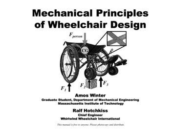
Mechanical Principlesof Wheelchair DesignFpersonCGF1F2F3Amos WinterGraduate Student, Department of Mechanical EngineeringMassachusetts Institute of TechnologyRalf HotchkissChief EngineerWhirlwind Wheelchair InternationalThis manual is free to anyone. Please photocopy and distribute.
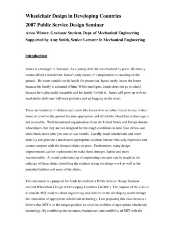
ForcesWhere usefulSeatForangeForange 2 NFrameWheelsFootrestsAdd forces:DescriptionA force is the amount one object tries to push orpull another object. The earth exerts a force onevery object, pulling it towards the ground. Thisis known as the force due to gravity. When youmeasure the weight of a person, you aremeasuring the force of gravity pulling on him.When an object is stationary all the forces actingon it are balanced. When the forces are notbalanced, the object will move. Forces aremeasured in Newtons or pounds. To convertkilograms to Newtons, multiply the number ofkilograms by 9.81. One kilogram is equal to 2.2lbs.0 Fhand ForangeFhand0 Fhand 2 N Fhand 2 NExample: Holding an orangeWhen you hold an orange you feel the force ofgravity trying to pull it to the ground. Yourhand has to push up on the orange to keep itfrom falling. The force the orange exerts onyour hand is equal in amount and opposite indirection to the force your hand is exerting onthe orange (see the equation). When you put theorange on a table, now the table is pushing on itwith an equal and opposite force. When youdrop the orange the forces on it are unbalanced.The orange falls because the force of gravitypulls it to the ground.This manual is free to anyone. Please photocopy and distribute.1
Center of gravityWhere usefulFwrenchFwrench 10 dle LheadAdd forces:DescriptionThe center of gravity (CG) of an object is thepoint where it can be balanced. If you wanted tothink of gravity pulling on an object at a singlepoint, the CG is that location. Understanding CGlocation is important in wheelchair design. Youcan approximate the force a person exerts on awheelchair as his total weight applied at the CGof his body, which is a point around his hips.0 F finger Fwrench F finger 10 NExample: Find the CG of a wrenchThe CG of the wrench is the point where thewrench can be balanced. More mass isconcentrated at the head, which makes the CGcloser to the head and not at the center of thehandle.This manual is free to anyone. Please photocopy and distribute.2
Free body diagramWhere usefulSeatFrameWheelsFperson 500 NAdd forces:Fperson0 2 Fcaster 2 Fwheel FpersonFwheel ?CGFcaster ?FootrestsFcasterDescriptionA free body diagram (FBD) is a visualrepresentation of the forces acting on an object.You have already seen FBDs in the previousexamples. As in the case of stationary objects,like the orange and wrench example, there areforces acting on them to balance the force ofgravity pulling them to the ground.FwheelExample: Sitting in a wheelchairThe figure shows the FBD of a person in awheelchair. If you know the weight of theperson you know the force her body exerts onthe wheelchair. Because the wheelchair is notmoving the forces the ground exerts on thewheels and casters must add up to be equal andopposite to the force from the person’s weight(note the “Add forces” equation is for 2 wheelsand 2 casters). In the next sections you willlearn how to calculate the forces exerted by theground on the wheels and casters.This manual is free to anyone. Please photocopy and distribute.3
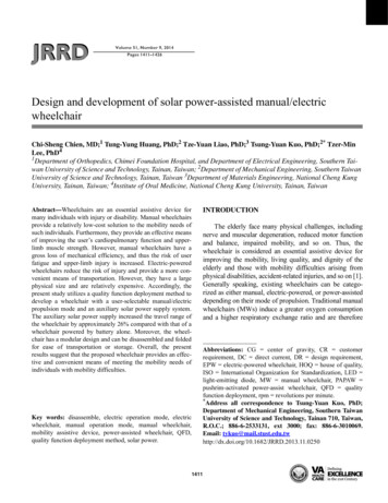
MomentsFwrench 10NWhere usefulFrameWheelsACGFhandleLhandle 12cmAdd forces:DescriptionA moment is like a force, but instead of trying topush an object it tries to twist it. A moment is aforce applied to a lever arm. When you tighten abolt, you apply a moment to the bolt with awrench. You produce the force with your bodyand the lever arm is the handle of the wrench.The moment is calculated by multiplying theforce times the perpendicular (at a 90o angle)distance from the pivot point. In every FBD, ifthe object is stationary, both the forces andmoments need to add up to zero.Lhead 8cmFhead0 Fhandle Fhead Fwrench Fhandle Fhead 10 NAdd moments: 0 Fwrench (Lhandle ) Fhead ( Lhandle Lhead )(L ) 10 N (12cm )FF wrench handle 6N F 4Nhead( Lhandle Lhead )(12cm 8cm )handleExample: Find forces with momentsSupport a wrench on two fingers, as shown inthe figure above. Since the object is not movingwe know the moments at each point must addup to zero. Calculating moments from point A,the moment from the weight of the wrench,which acts at the CG, tries to make the wrenchspin clockwise. The moment from our fingerunder the head tries to make the wrench spinanticlockwise (negative direction). Knowing themoments add to zero we can calculate the forceat the head. Use the addition of vertical forcesto find the force at the handle.This manual is free to anyone. Please photocopy and distribute.4
Add forces:Tipping angle:0 2 Fcasters 2 Fwheels Fpersontan θ tip Fperson0 2 Fcasters 2 Fwheels 500 NAdd moments:0 Fperson (Lcaster ) 2 Fwheel ( Lcaster Lwheel )FwheelAA θ tip arctan B B Can also calculate θtip fromheight wheels lift off ground h Aθ tip arcsin tip 2A CG500 N (40.6cm ) 200 N( 40.6cm 10.2cm ) Fcaster 50 NCGTipping angle and height fordifferent chairs geometries:(L )F person caster( Lcaster Lwheel )Fwheel ample: Forces on a wheelchairExample: Wheelchair tipping angleFind the forces acting on the wheels of thewheelchair in the above figure. If you know theweight of the person in the chair, the location ofher CG, and the distance between the wheels,you can calculate the forces on the wheels byusing moments. The calculations in theexample above add the moments about the frontcaster.A wheelchair will tip over when the forces andmoments acting on the chair becomeunbalanced. When the wheelchair tips to a pointwhere the CG of the user is vertically alignedwith the point where the wheel contacts theground, the chair is unstable. The angle thewheelchair makes with the ground at this pointis called the tipping angle (θtip), as shown in thefigure above. If the wheelchair tips further itwill fall over because there is no moment tocounteract the moment generated by the CG.This manual is free to anyone. Please photocopy and distribute.5
Internal forcesMnutCutFhandWhere usefulFrameWheelsL/2FnutLFhandMcutAdd forces:Fnut Fcut FhandAdd moments:DescriptionForces and moments also act on the inside of anobject. We can use the same methods as in theprevious examples to find internal forces andmoments. If an object is stationary, you knowthat all the forces and moments have to balanceeach other. There are some different terms usedto describe what occurs inside an object: Forcesthat try to stretch or compress an object arecalled tensile (stretch) and compressive(compress) forces. Forces trying to tear theobject are called shear forces. Moments are stillcalled moments on the inside of the object.LM nut Fhand ( L), M cut Fhand 2 FcutL/2Example: Moments inside a wrenchThe moment a wrench applies to a nut is theforce multiplied by the length of the handle.There is a moment at the head but no momentat the end of the handle. Now imagine taking acut of the wench and drawing a FBD of bothpieces, which are stationary. The forces andmoments that act on the surface where the cutwas made on one piece are equal and oppositeto those on the cut surface of the other piece.Imagine cuts at different places along thewrench and notice the internal momentdecreases from the head to the handle.This manual is free to anyone. Please photocopy and distribute.6
Faxle-vert0 Fperson Faxle horiz Faxle horiz 500 N0 Fperson Faxle vert Faxle vert 500 NLFaxle-horizRAdd forces:MaxleAdd moments:0 Fperson ( L ) Fperson ( R ) M AxleM axle Fperson (R L )M axle 500 N (0.305m 0.076m )FpersonFpersonFperson 500NR 0.305mL 0.076mM axle 114.5N mExample: Internal moments and forces in a wheelchair axleThe forces and moments acting on the rear axle of a wheelchair can be calculated the same way as forthe wrench in the previous example. The maximum moment occurs where the axel is welded to theframe. Think about what might cause moments on the axle. There are vertical forces exerted on thewheel from the ground, but there also may be horizontal forces that act on the wheel when the chairtips over. The total moment in the axle is difficult to calculate and requires using trigonometry. If youare comfortable with trigonometry determine the moments in the axle when the chair is at the tippingangle. As an estimation, calculate the moments caused from the full weight of a person pushing onone rear wheel, both vertically and horizontally. As you will see in the next sections, the moment inthe axle will determine if the metal is strong enough. See the figure for the axle-moment calculation.This manual is free to anyone. Please photocopy and distribute.7
Area, volume, massWhere usefulSeatbDensity ρLhLhbbhA 2V ALArea A bhVolume V ALFrameIn engineering you often need to calculate thearea or volume of a part. Area is important whencalculating the stress (see next section) andvolume is important when calculating theweight. You can calculate the weight of anobject if you know its volume and density.Density is a material property that tells howmuch mass there is for a given volume. Forexample, the density of water is 1 gram per eachcubic centimeter (written as 1g/cm3) and thedensity of steel is 7.8g/cm3. Steel is heavier thanwater, thus it sinks. If you want to know themass of a steel part, you would multiply thedensity of the steel by the volume of the part.LL didA FootrestsMaterialπd 24V ALRubberA π(d2o4V AL d i2 )(Butyl)Plastic(PVC)1213Example: Calculating mass of a partFor example, if your steel part had thedimensions of 10cm by 10cm by 20cm, thevolume would be 10cm X 10cm X 20cm 2000cm3. The mass would then be 7.8g/cm3 X2000cm3 15600g (notice the units of cm3cancelled out). 15600g is the same as 156kg.This manual is free to anyone. Please photocopy and distribute.8
RoRiL3L2L1Ri 76cmRo 76cmL1 76cmL2 51cmL3 76cmL4 81cmL5 13cmρsteel 7.8g/cm3Find the area of the frame tubing:A π (Ro2 Ri2 ) π (0.952 0.762 ) 1.02cm 2Find the total length of frame tubing:Ltotal L1 L2 L3 L4 L5Ltotal 76cm 51cm 76cm 81cm 13cmLtotal 297cmFind the volume of steel:V A Ltotal 1.02cm 2 297cm 303cm 3L4L5Find the mass of the frame:7.8 gm ρ steelV 303cm 3 2363g 2.36kg3cmExample: Mass of one side of wheelchair frameYou can estimate the total weight of a frame by adding up the weight of all the tubing in the frame. Ifyou know the inner diameter, outer diameter, and length of each tube you can calculate the volume. Ifyou know the density of the tubing material, you can calculate the total mass. See the above examplefor calculating the mass of a frame.This manual is free to anyone. Please photocopy and distribute.9
Axial stressF 5NStress σ FAF 5NWhere usefulFrameAxlesA1 62mm2A2 1.3mm2WheelsBearingsσ1 DescriptionStress is defined as the force acting on an objectdivided by the area over which it is acting. Forexample, push on a table with your finger. Thestress you exert on the table at the point underyour finger is the force with which you pushdivided by the area of your finger that is incontact with the table. Materials fail by bending,tearing, breaking, or stretching when they hit acertain level of stress. Axial stress tries to pull orcompress a material (from tensile andcompressive forces). Shear stress tries to tear amaterial (from shear forces).5N80645N 262mmm2σ2 5N3846154 N 21.3mmm2σ 1 σ 2Example: Feeling stress with skinPush the fat end of a pen or pencil into yourskin with a certain amount of force. Now flipthe pen around and use the same amount offorce to push the sharp end into your skin. Thesharp end hurts because it exerts a higher stresson your skin. Your body prevents you fromtearing your skin by using pain to tell you ifyour skin is getting stressed too much. Eventhough you used the same amount of force inboth tests, the area of the sharp end of thepencil is smaller, resulting in a higher stress onyour skin.This manual is free to anyone. Please photocopy and distribute.10
Behavior of metalsFhammerUltimate strength σUTSYield strength σyWhere usefulFrameAxlesWheelsBearingsDescriptionThe level of stress when a metal first starts todeform permanently under tensile orcompressive stresses is called the yieldstrength. If more stress is applied to a metalpast the yield strength eventually the materialwill break when it hits the ultimate strength.Shear stresses can also permanently deform ametal, and will be discussed in the next section.When engineering a wheelchair you alwayswant to use a saftey factor (SF), meaning youwant to prevent the stresses from coming withina certain factor of the yield strength. In mostcases a SF of 2 is enough but other casesrequire much higher SFs, up to 10 or 20.Dent SizeExample: Stressing sheet metalTake a piece of sheet metal and put it on a pieceof wood. Now take an indenter and hit it lightlywith a hammer. No dent is left because thematerial was not stressed enough topermanently deform. Now hit the materialharder and harder until you first start to make adent, which corresponds to the yield strength.Hit harder so you make bigger dents andeventually tear the metal, which corresponds tothe ultimate strength. As shown in the equationabove, the stress exerted on the metal is thehammer force divided by the indenter area.This manual is free to anyone. Please photocopy and distribute.11
FpersonFBD ofchair front:AFperson 500NFBD on 1 X-brace leg:t 4mmAMXF1CGF2MXFbF3From symmetryF3 Fperson 250 N2FBD on X-brace:FXRboltFbContactareaD 25mmRbolt 5mmAdd moments about left hole:0 Fb D M X Fb MX 2000 NDCalculate stress on contact area:FbFbN 31.8Contact area πRbolt tmmNNσ 31800000 2 σ y ,steel 330000000 2mmDesign is safe for static loading butpossibly not for shock loads (read below)σ F1F2L 200mmF33 points contact the groundLF3M X Fperson (L)M X 50000N mmExample: Stresses on the X-braceWhen the wheelchair goes over rough ground one wheel often lifts up, as shown in the figure. Thiscauses a moment to be transmitted through the X-brace, which causes stress on the bolt holes. Todetermine the stress we can first calculate the force on the left wheel (F3) from the FBD looking at thefront of the chair. Next we look at the side of the chair and visualize the moment in the X-brace causedby F3. Finally we calculate the stress on the bolt hole by estimating the contact area between the boltand the leg as ½ the surface area of the hole. Our final answer is well below the yield stress of mildsteel, but why do these holes still get over-stressed? The reason is shock loading, for instance when theuser jumps off a curb onto the road. Shock loading can easily magnify the static stresses (the stressescaused by gravity when stationary) by 10 times, which in our example would raise the stress near thesteel’s yield strength. One way to decrease the stress would be to increase the contact area.This manual is free to anyone. Please photocopy and distribute.12
Modulus and strainWhere usefulFrameAxlesWheelsBearingsDescriptionThe modulus of elasticity (E) is a materialproperty that tells how much a material tries notto deform when it is under stress. Strain is themeasure of how much a material deforms whenunder stress. Imagine pulling on a piece of metaland creating a stress. The material will stretch alittle because of the stress. The amount itstretches divided by its original length is thestrain. If you do not pull too hard the metal canspring back to its original length, which means itdeformed elastically. When metals are deformedelastically the modulus of elasticity equals thestress divided by the strain. This relationship isshown in the example to the right.σσUTS, alumMaterialσy,alumσy, steelσUTS, steelEsteelEalumModulus ofelasticityσE εL Loldstrain ε newLoldεEσy(N/mm2) er(Butyl)-17Plastic(PVC)250040Example: Stress, strain, modulusIn the sheet metal/indenter example, when youhit the indenter lightly it did not dent the metal.The metal deformed elastically and was able tospring back to its original shape. As shown inthe graph and equation above, the stress andstrain relate through the modulus of elasticityup to the yield strength of the material. Metalslike steel and aluminum, shown on the graph,have different modulus values. Steel feelsstiffer because it has a higher modulus, butsome types of aluminum (not all) are strongerbecause they have a higher yield strength.This manual is free to anyone. Please photocopy and distribute.13
Shear stressWhere usefulFrameFpunchSheetmetalDtMetal ear stress is the stress that tries to ripsomething apart. It is defined as the shear forcedivided by the area over which the force isacting. The shear strength of metals, the amountof shear stress to cause failure, is approximately½ the yield strength. This means you can easilycalculate the amount of shear stress a part canwithstand by knowing the yield strength. Makesure the shear stressess are below ½ the yieldstrength. If you used a safety factor of 2, whichis good engineering practice, you would makesure the shear stress is below ¼ the yieldstrength.Sheet metalArea of metal being sheared:A πDtYield strength σyShear strength τy σy/2Punch force:Fpunch σ yπDyσ yPunchedholeτy A 2 Fpunch 2Example: Metal punchA punch uses shear stress to make a hole insheet metal. We can calculate the amount offorce it takes to make the hole by knowing theyield strength (σy) and thickness (t) of thematerial and the diameter of the punch (D). Seethe example for the equation to predictpunching force. To find the force required forany punching operation, all you have to do isdetermine the shear area and know the materialproperties of the metal getting punch.This manual is free to anyone. Please photocopy and distribute.14
Fperson 500NArea of metal being sheared:πD 2A 4Shear stress:D 10mmσ y ,steel 330Nmm 2FpersonDFperson500 NN 6.37π (10mm ) 2Amm 24σ y ,steelNN 165 τ 6.3722mmmm 2τ FpersonSince the shear strength of the bolt is muchlarger than the shear stress, the bolt isplenty strong enough for the X-brace.Example: Shear stresses on boltsSometimes bolts are subjected to shear stresses. One example is in the X-brace pivot of a wheelchair.Under normal conditions, when the wheelchair is upright and on level ground, no shear stress exists inthe bolt. But as the wheelchair frame flexes, shear stresses can be exerted on the bolt where the twolegs of the X-brace meet. If you know the forces the legs of the X-brace apply to the bolt and thediameter of the bolt, you can calculate the amount of shear stress in the bolt. To estimate the shearforce you can use the weight of the person in the chair. Remember shock loads will also exist, so theactual forces might be many times the person’s weight. See the above example for the shear stresscalculation and to confirm the bolt is strong enough to withstand shock loading.This manual is free to anyone. Please photocopy and distribute.15
Bending stressTensile stressesWhere en a part is bent the applied moment createsstresses in the material. On one side of the partthe material is stretched and thus has tensilestresses. On the other side the material iscompressed by compressive stresses. Mostmetals can be bent a little bit (elastically) andspring back to their original shape. If you bendmetal too far it will pertinently deform becausethe tensile and compressive stresses willbecome larger than the yield stress of thematerial. As you will see in the next section, themoment in a part directly relates to the bendingstresses.Example: Bending a spoonTake the handle of a spoon with the flat side up.Bend the handle slightly and it will spring back.Bend it a little farther and it will bepermanently bent. When the spoon is bentdownward (as shown) the top of the spoon isbeing stretched by tensile stresses and thebottom is being compressed by compressivestresses. The spoon permanently bends whentensile and compressive stresses become largerthan the yield stress of the metal from whichthe spoon is made.This manual is free to anyone. Please photocopy and distribute.16
Moment of inertiaWhere usefulFrameTensile stressesMMAxlesCompressivestressesDescriptionThe strength and stiffness of a part dependsgreatly on the part’s geometry. When a part isbent the material at the outer surface feels thehighest stress. If the part is made thicker thematerial at the outer surface has more leverage,so the part will be stronger. The part will alsobe stiffer because it will bend less under a givenmoment. The moment of inertia (I) is a measureof how well the part geometry uses material tocounteract bending moments. As you will seeon the next page, the maximum stress in a partis directly related to the applied moment, thethickness of the part, and the moment of inertia.Example: Bending a spoon two waysUse the same spoon you bent in the lastexample. Now flip it so the thin side is facingup and try bending it. The amount of materialdid not change but the spoon seems strongerand stiffer because the moment of inertia ishigher with the thin side up than with the flatside up. If you know the moment applied to thepart, and the moment of inertia, you can findthe maximum stress the part experiences. Seethe next example for the moment of inertia of avariety of shapes as well as the maximum stressfelt by each shape when a moment is applied.This manual is free to anyone. Please photocopy and distribute.17
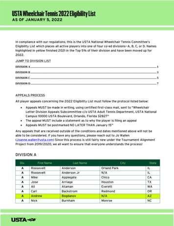
Loadingcondition formax stressequationsSolid axled 1.7cmbhhM3I Mhbh,σ max 2I12b2 Mhbh 3I , σ max 3I36doMMax stress σ maxσ maxI 4I πd σ Md, max2I64L 7.6cmI didMoment ofinertia Iπ64Hollow axledo 2.5cmdi 2.0cm(d4oσ max Md 32 M 2.07 M2Iπd 3mass mMd o2Im ρIncreasing the moment of inertia of a partmakes it both stronger and stiffer. Thegeometry of the part determines the moment ofinertia. This fact is very powerful, as it allowsparts to be made stronger without adding morematerial. Consider the frame of a bicycle; thetubes are hollow to maintain a large moment ofinertia while keeping the weight low. Theabove figure shows some common shapes ofwheelchair components and how to calculatethe moment of inertia and the maximum stresson the part under an applied moment.I 64 d i4 ),Example: Shape/moment of inertiaL 7.6cmπd 4πd 2464(d4o d i4 ),Md o32 Md o 2Iπ (d o4 d i4 ) 1.10 Mσ max σ maxL, 17.3ρπm ρπ (d 02 d i2 )4L 13.4 ρExample: Stress in wheelchair axleUsing your knowledge of moment of inertiayou can calculate the strength of a rearwheelchair axle. The figure above shows ahollow and solid axle. Both axles are the samelength, have the same moment applied (M), andare made of the same material (ρ). As you cansee from the calculation, the hollow axle is 88%stronger (because it has a lower stress under thesame moment) and 29% lighter than the solidaxle. By just changing the geometry (andmoment of inertia) a part can be madesignificantly stronger and lighter.This manual is free to anyone. Please photocopy and distribute.18
Stiffness vs. strengthColumnFAWhere iffness (k) is defined as the force applied to anobject divided by the resulting deflection. Forexample, when you push on a spring with a forceit compresses, resulting in a deflection. Thestiffness of a material depends on the modulusof elasticity. The stiffness and strength of a partdepends on the modulus and the part’s geometry.Just because something is stiff does not mean itis strong. Rubber bands are strong but have verylow stiffness. Glass is very stiff but not strongwhen it is bent. Steel is a great material becauseit is stiff and strong. It makes a wheelchairrugged and feel sturdy.IFLLAxlesWheelsCenter-loadedbeamGroundδ deflectionk k FδFδEAk Lk L3EIL3k k Fδ48 EIL3Example: Stiffness of different partsAll parts have a certain amount of stiffness. Thestiffness of a part depends on the material andthe geometry. Equations for the stiffness ofdifferent parts are given in the figure above.Notice that the stiffness of each part has themodulus of elasticity (E) in the equation. Thismeans the part can be made stiffer if it is madefrom a material with a higher modulus ofelasticity. In the beam examples, stiffness alsoincreases with the moment of inertia.This manual is free to anyone. Please photocopy and distribute.19
Stress and failureFor each axle: d 17mm, I 4100mm4Where usefulFvert 500 N , M axle Fvert (L )FMdσ shear vert , σ bend FootrestsDescriptionParts in wheelchairs can fail from different kindsof stresses, including compressive stresses (inbearings), bending stresses (in axles), or shearstresses (in cotter pins). It is the job of anengineer to determine what type of stress maycause failure. In most instances one kind ofstress will be much higher than the others so thepart will fail due to the highest stress. In otherinstances if two stresses are about the samelevel, for example bending and shear, you haveto use an equivalent stress. The equivalent stresscan be approximated as 2 times the largestindividual stress (see the example for using anequivalent stress).L 76mmNσ shear 2.2mm 2Nσ bend 78.9mm 2 σ bend σ shearL 3mmNmm 2Nσ bend 3.1mm 2 σ bend σ shearσ shear 2.2use 2σ bend as σ maxL 0.5mmNmm 2Nσ bend 0.5mm 2 σ shear σ bendσ shear 2.2Example: Axle length and stressThe axles in this example are under simplecantilevered loading. In a normal to very longaxle bending stresses will be the largest type ofstress. In a very short axle the shear stresseswill dominate. In a medium length axle theshear and bending stresses will be about thesame size. In this case an equivalent stress hasto be used. If the equivalent stress reaches theyield stress of the material the axle will fail. Seethe above examples for calculating stresses foreach type of axle.This manual is free to anyone. Please photocopy and distribute.20
Stress concentrationMMK 3Where usefulFrameAxles3σσFFK 3CastersMMhh/5DescriptionWhen a part has a sudden change in geometrythe stresses will be higher in that area, resultingin a stress concentration (K). The stressconcentration is a number that tells you howmuch the geometry intensifies the stress. Tofind the actual stress at a location, first calculatethe stress without the concentration and thenmultiply by the stress concentration (see theexample for stress concentrations in differentgeometries). As a conservative estimate, moststress concentrations are about 3. This means ifyou have a sudden change in geometry, plan forthe stresses at the change to be about 3 timeslarger than in the rest of the part.No stressconcentrationExample: Common concentrationsThe figure above shows stress concentrationsfor common geometries. You can decreasestress concentrations by using a more gradualgeometry (example: use a fillet instead of asharp corner) Note: If you need to put a hole ina part that has a moment applied to it, drill thehole near the center, as the highest stresses willbe on the outer surface of the part (see thefigure). If the hole diameter is small comparedto the height of the part (less than 1/5th) you donot have to account for the stress concentration.This manual is free to anyone. Please photocopy and distribute.21
St. Venant’shWhere ionA good design rule of thumb to remember isthat effects (for example stress concentrationsor clamping force) on one part of a machine atone point are not felt 3 to 5 characteristiclengths away from that point. This is called St.Venant’s Principle. A characteristic length isthe important dimension at a specific locationin a machine. It may be a hole diameter, thethickness of a plate, or the diameter of a shaft.The opposite is also true: if you want a part tofeel an effect (for example being clampedfirmly into place) it should be held over 3 to 5characteristic lengths.Example: Caster frame designSt. Venant’s principle is very useful whendesigning wheelchair frames. If any partprotrudes more than 3 to 5 characteristiclengths away from the wheelchair (thecharacteristic length could be the tubingdiameter or the part height) then the framemight not feel stiff. The footrest frame onAfrican-made wheelchairs is very welldesigned. The footrests are cantilevered but donot extend more than 3 to 5 times the height ofthe caster frame.This manual is free to anyone. Please photocopy and distribute.22
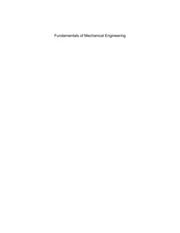
3σ 2σ σFBearings canbe hurtFdFShaftd3d5dBearingExample: Stress far from a holeExample: Cantilevered axlesYou learned the stress concentration at a hole ina part under tension will be approximately 3. Asyou move away from the hole the stressesreturn to a level as if the hole was not there. Inthis case the characteristic length is the holediameter. The part does not feel the stressconcentration 3 to 5 diameters away from thehole.If an axle extends too far from the bearingssupporting it the axle will flex and not feel stiff.The length an axle is cantilevered should not bemore than 3 to 5 times its diameter. If the axleis cantilevered any more the bearings can behurt by axle deflection.This manual is free to anyone. Please photocopy and distribute.23
Structural loopsFFWhere usefulFrameFootrestsDescriptionIf you want a frame or any kind of structure tobe stiff you should design the components ofthe structure to be close togethe
Mechanical Principles of Wheelchair Design Amos Winter Graduate Student, Department of Mechanical Engineering Massachusetts Institute of Technology Ralf Hotchkiss Chief Engineer Wh