Transcription
Router Architecture And IOSInternalsSession NumberPresentation ID 2001, Cisco Systems, Inc. All rights reserved.1
Agenda Routing and Switching Cisco IOS Switching Paths Cisco Express Forwarding Router Architectures & Parallel ExpressForwardingPresentation ID 2001, Cisco Systems, Inc. All rights reserved.2
Routing and SwitchingPresentation ID 2001, Cisco Systems, Inc. All rights reserved.3
SwitchingA The destination inthe layer two headerremains the samewhen a packetpasses through aswitchL2: to BL3: to BdataL2: to BL3: to BdataBPresentation ID 2001, Cisco Systems, Inc. All rights reserved.4
Routing Host A transmits thepacket to the routerAL2: to routerL3: to B The router determinesthe correct outboundport, then rewrites thelayer 2 header so thepacket is nowdestined to BPresentation ID 2001, Cisco Systems, Inc. All rights reserved.dataL2: to BL3: to BdataB5
Routing Switching, in the context ofrouters, involves thisprocess of looking up thenext hop, finding the layer 2rewrite “string,” rewriting thelayer 2 header, andtransmitting the packetPresentation ID 2001, Cisco Systems, Inc. All rights reserved.switchingtable6
Layer 3 Switching When the term “layer 3 switch”was first coined, it meantswitching packets in hardwarebased on the layer 3information However, the lines are rarely soneatly drawn in the real worldPresentation ID 2001, Cisco Systems, Inc. All rights reserved.SwitchingTable7
Routing Protocols andOther Sources Are Usedto Build the Routing TableInformationSourcesPresentation ID 2001, Cisco Systems, Inc. All rights reserved.RoutingTableControl Plane Data PlaneLayer 3 Switching8
ARP and OtherMethods Are Usedto Build the Layer 2Mapping TablesInformationSourcesPresentation ID 2001, Cisco Systems, Inc. All rights reserved.RoutingTableLayer 2MappingControl Plane Data PlaneLayer 3 Switching9
These Tables Are Used toBuild a Switching TableInformationSourcesPresentation ID 2001, Cisco Systems, Inc. All rights reserved.RoutingTableSwitchingTableLayer 2MappingControl Plane Data PlaneLayer 3 Switching10
InformationSourcesPresentation ID 2001, Cisco Systems, Inc. All rights reserved.SwitchingTableRoutingTableLayer 2MappingControl PlaneThe Switching TableIs then Used toSwitch PacketsData PlaneLayer 3 Switching11
Layer 3 Switching Where is switching done?On the main processor, in a“normal” processOn the main processor in aspecial mode (interrupt context)On a separate general purposeprocessorOn an application specificchip (ASIC)Presentation ID 2001, Cisco Systems, Inc. All rights reserved.SwitchingTable12
Cisco IOS Switching PathsPresentation ID 2001, Cisco Systems, Inc. All rights reserved.13
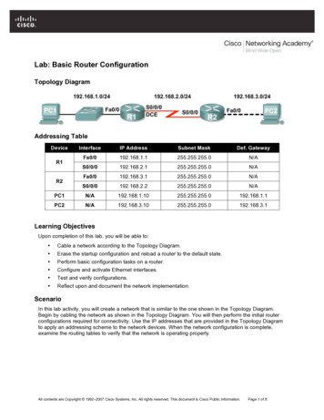
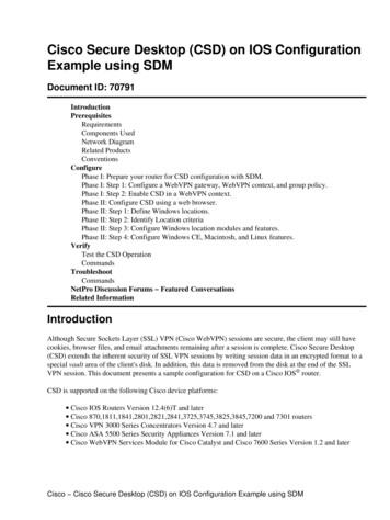
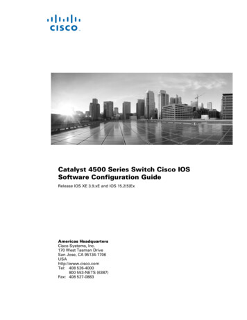
IOS Process SchedulingCriticalPriorityHigh PriorityMediumPriorityLow PriorityReady QueueScheduler Each disk represents a Process in the Process Ready Queue. Each Process is assigned a Priority (Critical, High, Medium or Low)Presentation ID 2001, Cisco Systems, Inc. All rights reserved.14
Router Switching Operation“Process Switching”CPUSoftware ‘Processes’ .Shared memoryRxRingBufferBufferBuffer1Interface ProcessorDMA’s packet into RXRing BufferPresentation ID 2001, Cisco Systems, Inc. All rights reserved.15
Router Switching Operation“Process Switching”Software ‘Processes’ .CPUShared memoryRxRingBufferBufferBufferHeader2Interface Driver CodeDecodes packet header andbuilds Buffer Header withL3 InfoPresentation ID 2001, Cisco Systems, Inc. All rights reserved.16
Router Switching Operation“Process Switching”XCPUSoftware ‘Processes’ .Shared memoryRX InterruptRxRingBufferBufferBufferHeader3Interface processor generatesRX Interrupt to CPU.Presentation ID 2001, Cisco Systems, Inc. All rights reserved.17
Router Switching Operation“Process Switching”4Software ‘Processes’ areresumed at the point thewere suspended when theRX Interrupt arrivedCPUWhen Packet passed toProcessor, Bufferownership transferred toProcessor.As Ownership has passedInterrupt released.Shared memoryRxRingBufferBufferBufferPresentation ID 2001, Cisco Systems, Inc. All rights reserved.Header18
Router Switching Operation“Process Switching”Software ‘Processes’ .CPU5ip inputRxRingBufferBufferShared memoryPresentation ID 2001, Cisco Systems, Inc. All rights reserved.BufferHeaderProcessor returns toscheduled tasks. Packet isplaced on Input Hold Q(protocol dependant).Packet is idle waiting forInput Process to deal withPacket.19
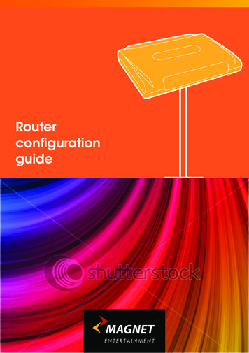
Router Switching Operation“Process Switching”Forwarding TableCPUCPUip input1.1.0.0/16via 172.16.2.110.1.1.0/24via 172.16.1.1ip outputBuffer HeaderShared memory6Input Process Looks upDestination in ForwardingTable. Determines O/Pinterface. Writes new MACheader. Places Packet inOutput QPresentation ID 2001, Cisco Systems, Inc. All rights reserved.20
Router Switching Operation“Process Switching”XCPUSoftware ‘Processes’ .ip outputBuffer HeaderSystem bufferTx RingShared memory7Output Process placespacket on output interfaceTX Ring Buffer.Presentation ID 2001, Cisco Systems, Inc. All rights reserved.21
Router Switching Operation“Process Switching”XCPUSoftware ‘Processes’ .Buffer HeaderTxRingShared memory8Interface polls TX ring andDMA’s packets fortransmissionPresentation ID 2001, Cisco Systems, Inc. All rights reserved.22
Router Switching Operation"Process Switching”XCPUSoftware ‘Processes’ .TX InterruptRxRingBufferBufferBuffer9Interface Instigates a TXinterrupt. Incrementcounters, SNMP etc.Presentation ID 2001, Cisco Systems, Inc. All rights reserved.23
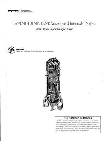
Demand Generated Cache BasedSwitching (“Fast” Switching)CPUCPU MemoryForwarding TableARP Table1.1.0.0/16via 172.16.2.1172.16.1.1: 0F00080010.1.1.0/24via 172.16.1.1172.16.2.1: 10134567A.ECE030178654Fast n IDAge00:00:1500:00:15InterfaceEthernet0Serial1 2001, Cisco Systems, Inc. All rights reserved.Next Hop172.16.2.1 14 00000C7EF7CF00E0B06423F60800172.16.1.1 4 0F00080024
Router Switching Operation”Fast” SwitchingXCPUSoftware ‘Processes’ .RXRingBufferBufferBuffer1Interface ProcessorDMA’s packet into RXRing BufferPresentation ID 2001, Cisco Systems, Inc. All rights reserved.25
Router Switching Operation”Fast” SwitchingXCPUSoftware ‘Processes’ .RxRingBufferBufferBufferHeader2Interface Driver CodeDecodes packet header andbuilds Buffer Header withL3 InfoPresentation ID 2001, Cisco Systems, Inc. All rights reserved.26
Router Switching Operation”Fast” SwitchingSimplified Optimum CacheXAgeI/F Next Hop00:00:15 E0 10.1.2.1 14 aae0cd.00:00:15 S1 10.2.3.1 4 0f000800RxRingCPUSoftware‘Processes’RX ufferHeader3Interface processorgenerates RX Interrupt toCPU.CPU Halts current processand attempts to fast switchpacketPresentation ID 2001, Cisco Systems, Inc. All rights reserved.27
Router Switching Operation”Fast” SwitchingSimplified Optimum CachePrefix10.1.2.3/3211.1.2.0/24XAgeI/F Next Hop00:00:15 E0 10.1.2.1 14 aae0cd.00:00:15 S1 10.2.3.1 4 0f000800CPUSoftware ‘Processes’ .4RxRingRX InterruptOptimum Cache entry usedto Write MAC headerBufferBufferBufferPresentation ID 2001, Cisco Systems, Inc. All rights reserved.Header28
Router Switching Operation”Fast” SwitchingXCPUSoftware ‘Processes’ .Shared memoryRX Interruptip outputBuffer HeaderTXRing5If Output Q is Empty packetis placed directly on the TXRing.A packet in the Output HoldQ, will force other packetsdestined for that interfaceto be placed in the Q.Presentation ID 2001, Cisco Systems, Inc. All rights reserved.29
Router Switching Operation”Fast” SwitchingRxRingBufferTx InterruptCPUBufferBuffer6Interface Instigates a TXinterrupt. Incrementcounters, SNMP etc.Presentation ID 2001, Cisco Systems, Inc. All rights reserved.30
Demand Generated Cache BasedSwitching Issues First packet towards a given destination is alwaysprocess switched Fast cache entries must be timed out periodically toprevent stale information from being used in switching When an arp entry or the routing table changes, wemust clear some portion of the fast cache and wait forprocess switched traffic to rebuild it We store a prebuilt mac header for each possibledestination. This waste space and causes duplicatedeffortPresentation ID 2001, Cisco Systems, Inc. All rights reserved.31
Show Processes7206#show processesCPU utilization for five seconds: 0%/0%; one minute: 0%; five minutes: 0%PID QTy2 M*PC Runtime (ms)InvokeduSecsStacks TTY Process088693 9888/120000 Exec3 Lst 60655C583457361297332664 5740/60000 Check heaps4 Cwe 6064C268414000 5568/60000 Chunk Manager5 Cwe 6065BC701217705 5596/600014 Lwe 60719100560410371054 5236/600020 Cwe 60661090010 5608/60000 Critical Bkgnd21 Mwe 6061BC70232209650110164/120000 Net Background22 Lwe 605ACD38026011504/120000 Logger24 Msp 6061B1C032336127714035 Mwe 6074799842766466882 Msp 6061B20085188213280 Pool Manager0 ARP Input25 6920/90000 Per-Second Jobs6610648/120000 IP Input3994 5660/60000 Per-minute JobsFor the 5 Sec window we have both the total CPU time and the Interrupt timePresentation ID 2001, Cisco Systems, Inc. All rights reserved.32
Show Processes CPU7206#show processes cpuCPU utilization for five seconds: 0%/0%; one minute: 0%; five minutes: 0%PIDRuntime(ms)InvokeduSecs5Sec1Min5Min TTY Process2682272990.00%0.00%0.00%0 Exec336892013842526650.08%0.02%0.00%0 Check heaps44140000.00%0.00%0.00%0 Chunk Manager520219520.00%0.00%0.00%0 Pool Manager146608119562550.00%0.00%0.00%0 ARP Input200100.00%0.00%0.00%0 Critical Bkgnd2124821824210.00%0.00%0.00%0 Net Background2202800.00%0.00%0.00%0 Logger24357041362619260.00%0.00%0.00%0 Per-Second Jobs35452068993650.00%0.00%0.00%0 IP Input82908962275939930.00%0.00%0.00%0 Per-minute JobsMore specific information on the CPU time occupied by the ProcessesPresentation ID 2001, Cisco Systems, Inc. All rights reserved.33
Cisco Express ForwardingPresentation ID 2001, Cisco Systems, Inc. All rights reserved.34
Cisco Express Forwarding Background CEF Theory The CEF Mtrie The Adjacency Table Adjacency Table Entries Load Sharing with CEF CEF AccountingPresentation ID 2001, Cisco Systems, Inc. All rights reserved.35
Background: Process Level Switching Process Level Switching has speedlimitations on high speed networksPresentation ID 2001, Cisco Systems, Inc. All rights reserved.36
Background: Fast Switching Caching the results of the lookup routines wasthe first solution and is known as Fast Switching This solution encounters scalability problems onInternet backbone routers where the routingtable is changing rapidly and there are manydifferent flows of traffic CEF (Cisco Express Forwarding) was developedto address the scalability issues of Process andFast Switching CEF doesn’t cache switching information, itbuilds switching tablesPresentation ID 2001, Cisco Systems, Inc. All rights reserved.37
CEF TheoryWhat Do We Need to Switch a Packet?Destination AddressMAC Header Rewrite bound Interface InformationPresentation ID 2001, Cisco Systems, Inc. All rights reserved.38
CEF TheoryCEF Builds Two Tables to Containthis Information:The CEF MtrieThe Adjacency TablePresentation ID 2001, Cisco Systems, Inc. All rights reserved.39
CEF Packet Switching Read in packet from the interface and storepacket into memory Raise an interrupt to the processor; the rest ofthe packet switching takes place within theinterrupt Use CEF mtrie to lookup packet destination;determine correct next-hop info by followingpointer in the last CEF mtrie node Use Adjacency table info to rewrite physicallayer header Place packet on the outbound interface queuePresentation ID 2001, Cisco Systems, Inc. All rights reserved.40
CEF TheoryWhat’s the Difference between aTree and a Trie? .pointer to parentpointer to childMAC header rewrite .The MAC Header Rewrite Information Is Stored in the Tree ItselfPresentation ID 2001, Cisco Systems, Inc. All rights reserved.41
CEF TheoryWhat’s the Difference between aTree and a Trie? .pointer to parentpointer to childMAC header rewrite .A Pointer to the MAC Header Information Is Stored in the Trie,and the MAC Header Information Itself Is Stored in aSeparate TablePresentation ID 2001, Cisco Systems, Inc. All rights reserved.42
The CEF Mtrie0010255256 Children160255256 Children256 Children172.16.1.0Presentation ID255256 Children 2001, Cisco Systems, Inc. All rights reserved.172255root43
The CEF Mtrie0 Nodes point toother nodes orleaves255012550162550172255rootPresentation ID 2001, Cisco Systems, Inc. All rights reserved.44
The CEF Mtrie0 Leaves point to theadjacency table255012550162550172255rootPresentation ID 2001, Cisco Systems, Inc. All rights reserved.45
The CEF MTrieRouter#sh ip cef summaryIP CEF with switching (Table Version 4)4 routes, 0 reresolve, 0 unresolved (0 old, 0 new), peak 04 leaves, 8 nodes, 8832 bytes, 4 inserts, 0 invalidations0 load sharing elements, 0 bytes, 0 referencesuniversal per-destination load sharing algorithm, id 20340B241 CEF resets, 0 revisions of existing leaves0 in-place/0 aborted modificationsResolution Timer: Exponential (currently 1s, peak 1s)refcounts: 533 leaf, 536 nodePresentation ID 2001, Cisco Systems, Inc. All rights reserved.46
The CEF MtrieMainProcessorCacheRIBRXInputQueueThe PipePresentation IDOutputQueueTXThe Pipe 2001, Cisco Systems, Inc. All rights reserved.47
The CEF Mtrie Notes Where in the switching path do we buildthe CEF table? Nowhere! The CEF table is built from therouting table before (and while) packets arebeing switched Because the CEF table is directly related tothe routing table, we can build it for everydestination in the routing table withoutwaiting on any packets to be switchedPresentation ID 2001, Cisco Systems, Inc. All rights reserved.48
Two Separate Tables81100168router#show ip route1030192172172.30.0.0/24 is subnetted, 1 subnetsS172.30.100.8/32 via Serial 0/0C192.168.1.0/24 is directly connected, Ethernet 1/2S10.0.0.0/8 via POS 4/10The Routing Table and the CEF Mtrie Are Directly RelatedThe CEF Table Contains Reachability and Next Hop InformationPresentation ID 2001, Cisco Systems, Inc. All rights reserved.49
The CEF MtrieROOT0-255NULLEmpty TablePresentation ID 2001, Cisco Systems, Inc. All rights reserved.50
The CEF MtrieROOT0-255NULLAdd 10.0.0.0/8Presentation ID 2001, Cisco Systems, Inc. All rights reserved.51
The CEF Mtrie0-9NULL10.0.0.0/8ROOT1011-255NULLAdd 20.1.0.0/16Presentation ID 2001, Cisco Systems, Inc. All rights reserved.52
The CEF /1620201 2-25521-255NULLNULLAdd 20.1.1.0/24Presentation ID 2001, Cisco Systems, Inc. All rights reserved.53
The CEF .0/16120201 2-25521-255NULLNULL2-25520.1.1.0/2420.1.0.0/16Add 30.1.1.0/29Presentation ID 2001, Cisco Systems, Inc. All rights reserved.54
The CEF 61ROOT2021-29201 2-255NULLNULL11Presentation ID 2001, Cisco Systems, Inc. All rights reserved.NULLNULL2-255NULL10-7Add 30.1.1.0/30301 8-25530.1.1.0/29NULL55
The CEF 61ROOT2021-29201 2-255NULL0NULL1NULL0-3Add 30.1.0.0/16Presentation ID 2001, Cisco Systems, Inc. All rights reserved.301 .1.0/30NULLNULL2-25514-7NULL8-25530.1.1.0/29NULL56
The CEF 61ROOT2021-29201 3Add 0.0.0.0/0Presentation ID 2001, Cisco Systems, Inc. All rights reserved.301 -730.1.0.0/168-25530.1.1.0/2930.1.0.0/1657
The CEF .0/0020.1.0.0/161ROOT2021-29201 ion ID 2001, Cisco Systems, Inc. All rights reserved.301 25530.1.1.0/2930.1.0.0/1658
The CEF Mtrie Normally there are 4 levels of nodes witheach node having 255 children Prefix and traffic distribution sometimesmakes the mtrie perform better if there aredifferent numbers of children for nodes ateach levelPresentation ID 2001, Cisco Systems, Inc. All rights reserved.59
The CEF MTrie010160256 Children255256 Children25501256 Children25564K0132 Children32512 Children51265,536 Children0root16-8-801256 Children2550132 Children32256 Children25600162,048 Children11-8-5-8Presentation ID1721720161,024 Children10-9-5-81721Kroot2Kroot 2001, Cisco Systems, Inc. All rights reserved.60
Path Through the CEF Switch CodeXCPUSoftware ‘Processes’ .RXRingBufferBufferBufferInterface ProcessorDMA’s packet into RXRing BufferPresentation ID 2001, Cisco Systems, Inc. All rights reserved.61
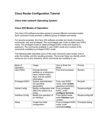
Path Through the CEF Switch Code1. A packet arrives at an input interface, RX Interrupt generatedgenerated2. Read IP Destination Prefix3. Search CEF’s FIB DB, using the Destination Prefix as Search Key3FIB DB256 wayMTRIEDestination PrefixPresentation ID 2001, Cisco Systems, Inc. All rights reserved.Search for FIB Entry62
Path Through the CEF Switch Code1. A packet arrives at an input interface, RX Interrupt generatedgenerated2. Read IP Destination Prefix3. Search CEF’s FIB DB, using the Destination Prefix as Search Key4. A Successful MTRIE Lookup will result in a FIB Entry being Found4a. If the MTRIE Lookup is unsuccessfulunsuccessful,, the packet will be droppedFIB DBDestination Prefix4mtrie infofastadjMTRIESearch for FIB Entry256 waypath[0]4a Not Switched – Packet DROPPEDPresentation ID 2001, Cisco Systems, Inc. All rights reserved.63
Path Through the CEF Switch Code1. A packet arrives at an input interface,, RX Interrupt generated2. Read IP Destination Prefix3. Search CEF’s FIB DB, using the Destination Prefix as Search Key4. A Successful MTRIE Lookup will result in a FIB Entry being Found4a. If the MTRIE Lookup is unsuccessful, the packet will be dropped5. FIB Path is selectedFIB DBDestination Prefixmtrie infofastadj256 wayMTRIEpath[0]Presentation ID 2001, Cisco Systems, Inc. All rights reserved.5Search for FIB Entry64
Path Through the CEF Switch Code1. A packet arrives at an input interface,, RX Interrupt generated2. Read IP Destination Prefix3. Search CEF’s FIB DB, using the Destination Prefix as Search Key4. A Successful MTRIE Lookup will result in a FIB Entry being Found4a. If the MTRIE Lookup is unsuccessful, the packet will be dropped5. FIB Path is selected6. Selected FIB Path will point to necessary entry in Adjacency TableFIB DBDestination Prefix46mtrie infofastadj5path[0]AdjacencyTableOutput I/FL2 Header256 wayMTRIESearch for FIBPresentation ID 2001, Cisco Systems, Inc. All rights reserved.65
Switch During the Receive Interrupt Features areprocessed along eachswitching path. Each featurerepresents a functioncall which may fail,succeed, or just notexist.Presentation ID 2001, Cisco Systems, Inc. All rights reserved.CEFInput Access ListNetwork AddressTranslationFastSwitch66
Switch During the Receive InterruptCEFFastmfrontPuFCE At any point while thepacket is beingprocessed, it can bepunted to the nextslower process byallowing theprocessor to jump tothe next pointer in thechain.tostFaPresentation ID 2001, Cisco Systems, Inc. All rights reserved.67
Switch During the Receive Interrupt At any point in thechain, the packetmay be also beenqueued forprocess switching.CEFFastEnqueue packet andterminate interruptPresentation ID 2001, Cisco Systems, Inc. All rights reserved.68
The CEF MtrieDepending on the Type of Route, a CEFTable Entry Can Be Several Different Types Attached Connected Receive RecursivePresentation ID 2001, Cisco Systems, Inc. All rights reserved.69
The CEF Mtrie Attached—An “attached” mtrie entrymeans the destination is attached tothe router Connected—A “connected” entry is theresult of an ip address being configuredon an interface An entry may be both Attached andConnectedPresentation ID 2001, Cisco Systems, Inc. All rights reserved.70
The CEF Mtrie Receive—Indicates packets that aredestined to the router and do not need tobe switched to another interface Recursive—References another node tofind the next-hop informationPresentation ID 2001, Cisco Systems, Inc. All rights reserved.71
The Adjacency Table The Mtrie is used to lookup the next-hop for a prefix The final node encounteredin the Mtrie during a prefixlookup includes a pointerto the correct next-hop inthe adjacency tableCEF MTrieOutbound InterfaceMAC Rewrite StringAdjacency TablePresentation ID 2001, Cisco Systems, Inc. All rights reserved.72
The Adjacency Tablerouter#show arpAddress The ARP Cache andthe Adjacency Tableare directly related The adjacency tabledoesn’t contain anyinformation aboutnetworks; it onlycontains informationabout next hopsPresentation ID 2001, Cisco Systems, Inc. All rights reserved.Hardware AddrInterface192.168.1.4 2B2B.2B2B.2B2B Ethernet 1/210.1.1.13C3C.3C3C.3C3C POS 4/1Serial 0/0Point2PointEthernet 1/22B2B.2B2B.2B2BPOS 4/13C3C.3C3C.3C3C73
The Adjacency Table Allows next-hops to change withoutchanging the mtrie A change in next-hop just requires thefinal mtrie node’s pointer to the adjacencytable to be updated Routing table changes also don’t impactthe adjacency tablePresentation ID 2001, Cisco Systems, Inc. All rights reserved.74
The Adjacency Table Update the FIB when changes in therouting table occur Update the adjacency table when changesin connected adjacencies occurPresentation ID 2001, Cisco Systems, Inc. All rights reserved.75
Adjacency Table Entries Auto adjacencies Punt Adjacencies Glean Adjacency Drop Adjacencies Discard Adjacencies Null Adjacencies Cached AdjacenciesPresentation ID 2001, Cisco Systems, Inc. All rights reserved.76
Adjacency Table Entries (Auto) Auto Adjacencies—The most commontype of adjacency; include all theinformation needed to rewrite the packetheader and place the packet in the properinterfaces output queuePresentation ID 2001, Cisco Systems, Inc. All rights reserved.77
Adjacency Table Entries (Auto)10.1.1.210.1.1.1Router(config)#ip route 70.0.0.0 255.0.0.0 10.1.1.270.0.0.0/8ADJMAC HeaderRewriteStringPresentation ID 2001, Cisco Systems, Inc. All rights reserved.78
Adjacency Table Entries Punt Adjacencies—A punt adjacencyindicates that the packet should beswitched by the next slower switchingschemePresentation ID 2001, Cisco Systems, Inc. All rights reserved.79
Adjacency Table Entries (Glean) Glean Adjacency—Only one per router;indicates that the destination is attachedto the router but the layer two informationhas not been acquired; results in an ARPrequest when a packet is switched to thisdestinationPresentation ID 2001, Cisco Systems, Inc. All rights reserved.80
Adjacency Table Entries (Glean)Router#sh ip interface briefInterfaceIP-Address OK? Method Status ProtocolEthernet0/020.0.0.1YES manual upupRouter#sh ip cef adjacency gleanPrefixNext ion ID 2001, Cisco Systems, Inc. All rights reserved.81
Adjacency Table Entries (Glean)10.1.1.210.1.1.0/32 Receive10.1.1.255/32 Receive10.1.1.1/32 Receive10.1.1.0/24 Attached10.1.1.110.1.1.0/24ADJGleanPresentation ID 2001, Cisco Systems, Inc. All rights reserved.82
Adjacency Table Entries (Glean)10.1.1.210.1.1.110.1.1.0/32 Receive10.1.1.255/32 Receive10.1.1.1/32 Receive10.1.1.0/24 Attached10.1.1.2/32 Attached10.1.1.0/24ADJGleanMACPresentation ID 2001, Cisco Systems, Inc. All rights reserved.83
Adjacency Table Entries Drop Adjacency—Indicates the packetshould be droppedPresentation ID 2001, Cisco Systems, Inc. All rights reserved.84
Adjacency Table Entries (Drop)Router#sh ip cef adjacency dropPresentation IDPrefixNext Hop224.0.0.0/4drop 2001, Cisco Systems, Inc. All rights reserved.Interface85
Adjacency Table Entries Discard Adjacency—Indicatesdestinations which are part of aloopback’s subnet, but are not the actualip address configured on the interfacePresentation ID 2001, Cisco Systems, Inc. All rights reserved.86
Adjacency Table Entries (Discard)Router(config)#int loop0Router(config-if)#ip addr 40.0.0.1 255.255.255.040.0.0.1/32ADJRouter#sh ip cef 40.0.0.240.0.0.0/24, version 3, attached, connectedDiscard40.0.0.0/240 packets, 0 bytesvia Loopback0, 0 dependenciesvalid discard adjacencyPresentation ID 2001, Cisco Systems, Inc. All rights reserved.87
Adjacency Table Entries Null Adjacency—Indicates the packetshould be switched to a Null interface onthe routerPresentation ID 2001, Cisco Systems, Inc. All rights reserved.88
Adjacency Table Entries (Null)Router(config)#ip route 60.0.0.0 255.0.0.0 null0Router#sh ip cef adjacency nullPrefixNext HopInterface60.0.0.0/8attachedNull0Presentation ID 2001, Cisco Systems, Inc. All rights reserved.89
CEF Show Commandsrouter#show ip cefPrefixNext 142.5InterfaceSerial4/3POS1/0Prefix: The Prefix of the Destination NetworkNext Hop: The Type of Adjacency or the NextHop Towards This DestinationInterface: The Interface Out Which to SendTraffic for This DestinationPresentation ID 2001, Cisco Systems, Inc. All rights reserved.90
CEF Show Commandsrouter#show ip cef 33.97.1.0 255.255.255.0 detail33.97.1.0/24, version 13, attached, connected, cached adjacency to Serial4/30 packets, 0 bytesvia Serial4/3, 0 dependenciesvalid cached adjacencyThe Type of Adjacency This CEFTable Entry Points toNumber of Table Entries Which Point to (Depend On)This EntryNumber of Packets and Bytes Which Have BeenSwitched Through This Entry; Configure IP CEFAccounting Per-prefix for This to WorkPresentation ID 2001, Cisco Systems, Inc. All rights reserved.91
CEF Show Commandsrouter#show ip cef summaryIP CEF with switching (Table Version 46), flags 0x022 routes, 0 reresolve, 0 unresolved (0 old, 0 new), peak 025 leaves, 19 nodes, 22960 bytes, 49 inserts, 24 invalidations0 load sharing elements, 0 bytes, 0 referencesuniversal per-destination load sharing algorithm, id F2F8D257Total Number of Entries in the CEF TableNumber of Entries Which Need to Be Re-resolvedNumber of Entries Which Do Not HaveResolved RecursionsPresentation ID 2001, Cisco Systems, Inc. All rights reserved.92
CEF Show Commandsrouter#show adjacency detailProtocol InterfaceAddressIPpoint2point(5)Serial4/00 packets, 0 bytesABC0F000800CEFexpires: 00:02:32refresh: 00:00:32A: Packets and Bytes Switched Through This AdjacencyB: MAC Header Rewrite StringC: When This Entry Will Be Refreshed; In This Case, AllPoint2Points Are Refreshed Every MinutePresentation ID 2001, Cisco Systems, Inc. All rights reserved.93
CEF Show Commandsrouter#show int ethernet1/0 statEthernet1/0Switching pathPkts InChars InPkts OutChars OutProcessor9771217014965557801456457133Route cache0000Total9771217014965557801456457133Route cache Includes CEF Switched PacketsPresentation ID 2001, Cisco Systems, Inc. All rights reserved.94
Router Architectures &Parallel ExpressForwardingPresentation ID 2001, Cisco Systems, Inc. All rights reserved.95
Introduction Routers have to deal in three “Planes” of operation:The “Control” PlaneBuilding and maintaining data structures such as “forwardingtables”The “Management” PlaneDealing with configuration files, gathering and providingstatistics, providing and responding to control protocolmessagesThe “Data” PlaneSwitching of packets, manipulation of packet (header andcontent), packet delivery scheduling (queuing)Presentation ID 2001, Cisco Systems, Inc. All rights reserved.96
Introduction – Consumable ResourcesCPUMemoryBandwidthWhen any all or all of the resources are exhausted, inconsistentbehavior will be observedPresentation ID 2001, Cisco Systems, Inc. All rights reserved.97
Routers Operationally Maintain/manipulate routing informationListen for updates/update neighbors Classify packets for manipulation/queuing/permit-deny, etc.Compare packets to classification lists and perform control Perform Layer 3 switchingCreate outbound Layer 2 encapsulationLayer 3 checksumTTL/hop count update Management/billing (statistics)Interface statistics—NetFlow exportTelnet, SNMP, ping, trace route, HTTPPresentation ID 2001, Cisco Systems, Inc. All rights reserved.98
Routers Functionally (Attempt to) switch packetsLayer 3 switching based on routing information (Attempt to) transmit packetsAccess outbound media Manipulate packetsChange contents of packet (CAR/NAT/compression/encryption) Consume packetsRouting protocol updates etc /services advertisements(SAP)/ICMP/SNMP Generate packetsRouting protocol packets/SAPs/ICMP/SNMPTunnels—GRE, IPSec, DLSw etc Presentation ID 2001, Cisco Systems, Inc. All rights reserved.99
Router Hardware Interface Processors The Central Processing Unit Memory The BackplanePresentation ID 2001, Cisco Systems, Inc. All rights reserved.100
The Central Processing Unit Provides horsepower for allcontrol plane functions, suchas system maintenance,building routing tables, etc. On some platforms, it alsoprovides the horsepower foractually switching packetsPresentation ID 2001, Cisco Systems, Inc. All rights reserved.101
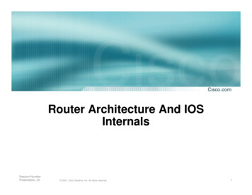
Shared Memory Architecture Applicable PlatformsCisco 1xxxCisco 2xxxCisco 3xxxCisco 4xxxPresentation ID 2001, Cisco Systems, Inc. All rights reserved.102
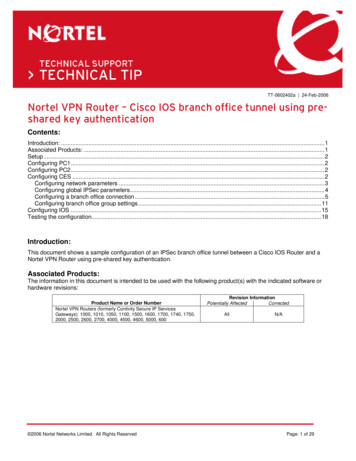
Shared Memory ArchitectureMemoryPacketSwitchingCPU AllocatedMemoryAllocatedMemorySwitching US/W Image/FilesCPU ceInterfaceData/Address/Control Bus’sInterfaceCPU QueuesPhysical Media Interfaces(Fixed or Modul
2001, Cisco Systems, Inc. All rights reserved. 1 Session Number Presentation_