Transcription
POCKETBLASTGUIDESEPTEMBER 2020AUSTRALIA PACIFIC AND ASIA
Stop. Describe the task.Think. List the hazards.Identify. Assess the risk.Plan. List the controls.Proceed. Decide what is next.Risk MatrixCONSEQUENCESLIKELIHOODMinimal e.g. First Aid Small spill of product Minor plant damageSignificant e.g. Recordable accident Medical treatment Plant damage Loss of containmentCatastrophic e.g. Severe injury or death Severe plant damage Major loss ofcontainmentVery LikelyBAAPossibleCBAVery UnlikelyCCBDecisionA Stop, Get Supervisor, JSERAB Stop, JSERAC Continue
Contents1 Blasthole Charge Weights2 Blast Calculations3 Rules of Thumb4 Typical Rock Properties5 Powder Factors6 Survey Offset Chart7 Secondary Blasting8 Blasting Nuisances9 Perimeter Blasting10 Underground Blasting11 Conversion Factors12 Packaged Explosives13 Initiating Systems14 Electronic Blasting Systems15 Bulk Systems Products16 Accessories
1. Blasthole Charge WeightsBlasthole Charge WeightsValues in table are kilograms of bulk explosive per metre of blastholeDiameterBulk explosive average in hole density 12.031305 1 9.2420.312007 .7132.9535.0137.0739.132519 7 814.8422.2729.6939.5842.0644.5347.012705810 17.1825.7634.3545.8048.6751.5354.3931112 3068.4191.2196.91102.61108.3178Table continued below
DiameterBulk explosive average in hole density 5715.2015.8316.47130185 200787 9.4251.4853.542519 7 849.4854.4356.9059.3861.8564.332705810 57.2662.9865.8468.7171.5774.4331112 31.11136.81142.51148.211. Blasthole Charge Weights
2. Blast CalculationsBlast CalculationsHole length, L (m) Charge length, C (m) (BH/cos β ) SuL – StVolume of charge per hole, Vc (litres) π D 2 /4000 C (D in mm)Mass of charge per hole, Mc (kg) Vc ρexplVolume of rock per hole, Vr (m3) B S BHTotal Blast volume, V (m3) Vr NTotal Blast Mass, M (t) V ρrockPowder Factor, PF (kg/m3) Mc / VrN Number of holes in blastρexpl Average inhole ExplosiveDensity (g/cm3)ρrock Rock density (t/m3)L Hole Length (m)Su Subgrade (m)St Stemming (m)BH Bench Height (m)β Blasthole angle measured fromvertical
Rules of ThumbThis table describes the most common ratios between blast designparameters for production blasting in rock. Special requirements may requirea design outside these rules.Hole Diameter DBurden (20 to 40) DSpacing (1.1 to 1.4) B(1.15 for even hole distribution ina staggered pattern)Subgrade (8 to 12) DStemming length (20 to 30) DStemming particle size 0.1DInitiation Timing Rules of ThumbTiming between holes for fragmentation, 3 to 8 ms per metre of hole spacing.Timing between rows for heave, 15 to 30 ms per metre of hole burden.The overall burden relief rate for surface production blasting is usually in therange of 10 to 20ms/m, measured perpendicular to the angle of initiation.3. Rules of Thumb
3. Rules of ThumbGolden Rules for Non-ElectricSurface DelaysMovement is always towards the initiation pointWhen using non-electric systems, the rock will always move towards theinitiation point. If the rock must go in a particular direction, select theinitiation point to suit.Always Use Reverse EchelonsAlways connect surface delays on the reverse echelon.
Never use forward echelonsConnecting surface delays on the forward echelon may cause anout-of-sequence initiation.Don't skip missing holesThis can cause an out-of-sequence initiation3. Rules of Thumb
3. Rules of ThumbGolden Rules for Non-ElectricSurface Delays Continued.Use dummy holesConnect missing holes as if they were there. This will keep the plannedsequence.Use dummy holesAlways pretend the missing hole is actually there when designing andtying up.
If the control row ends, drop back and continueTry to keep the control row connections parallel.Classic "V"Keep the sequence symmetrical around an imaginary line drawn backfrom the initiation point.3. Rules of Thumb
3. Rules of ThumbUsing Timing for ShapingSelect control row delays and echelon delays to change the direction ofmovement. Shorter control row delays promote forward movement,while shorter echelon delays stand the blast up.
Variations - Slow Down Back RowIt is common practice to add more time into the back row to providegreater relief and achieve better walls with less backbreak. This is a freeand easy design choice.Burden Relief RateThe Burden Relief Rate is an absolute measure of the timing of the blast.3. Rules of Thumb
4. Typical Rock PropertiesTypical Rock rength(MPa)Young’sModulus(GPa)Poisson’s RatioBasalt3.078 – 41220 – 1000.14 – 0.25Bauxite2.1Clay – dense, wet1.7Coal, Anthracite1.6Coal, Bituminous1.4Diabase2.8150 – 33010 – 1000.1 – 0.25Diorite3.0115 – 34025 – 300.1 – 0.8Dolerite2.8290 – 500Dolomite3.015 – 11820 – 840.1 – 0.2Earth, moist1.8Gneiss2.978 – 24025 – 600.1 – 0.19Granite2.7100 – 27525 – 700.15 – 0.34Gypsum2.8Haematite4.8Iron Ore4.9Limestone2.610 – 24510 – 800.1 – 0.23Limonite3.8Magnesite3.2Magnetite5.1Marble2.550 – 20060 – 900.2 – 0.35Material8 – 50Table continues below
ngth(MPa)Young’sModulus(GPa)Poisson’s RatioMica-Schist2.7Porphyry2.5Quartzite2.585 – 35026 – 1000.15 – 0.2Sandstone2.450 – 1605 – 860.1 – 0.3Shale2.620 – 1508 – 300.1 – 0.3Silica Sand2.6Siltstone2.2Slate2.898 – 19630 – 900.1 – 0.44Talc2.6Typical Powder Factors usedin Production BlastsTypical powder factorsused in bench blastsRock typeTypical powder factors usedin presplit and smooth blastingPF (kg/m3)Rock typePF (kg/m2)Strong0.8 – 1.2Strong0.6 – 0.9Medium0.6 – 0.8Medium0.4 – 0.5Soft0.4 – 0.6Soft0.2 – 0.3Very Soft 0.45. Powder Factors
6. Survey Offset ChartSurvey Offset ChartWhen using the clinometer on drill holes, remember that it has 90º as verticalso for a hole drilled at 20º, the clinometer should read 70º.Degrees fromvertical57.510Vertical Deptho/sHole Lengtho/sHole Lengtho/sHole 922.521.01.821.12.821.23.721.3
Degrees fromvertical12.51517.5Vertical Deptho/sHole Lengtho/sHole Lengtho/sHole 23.07.023.321.04.721.55.621.76.622.06. Survey Offset Chart
6. Survey Offset ChartSurvey Offset Chart continuedDegrees fromvertical2022.525Vertical Deptho/sHole Lengtho/sHole Lengtho/sHole .224.010.424.5
Secondary BlastingSecondary blasting can produce flyrock and noise if not carefully controlled.Popping Breaking boulders by placing an explosive charge in a blasthole drilled tothe approximate centre of the boulder. Use only sufficient explosive to break the boulder into manageable rock.Plaster Shooting Explosive is placed in firm contact with the surface of a boulder. Handy when time or drilling constraints apply. Boulders of 1.5 m thickness are the limit for plaster shooting. Explosive should be laid on top of, and in intimate contact with theboulder and covered with stiff mud or clay.Charge mass for secondary blastingTypical powder factors for boulder are in the range of 0.05 - 0.15kg/m3.Larger boulders typically need a higher Powder Factor.The powder factor also depends on the fragmentation required, numberof blasthole and placement of the charge.7. Secondary Blasting
8. Blasting NuisancesBlasting NuisancesAirblastBlasting generates overpressure, also called airblast. Airblast includes audibleand inaudible components.Regulatory authorities in Australia enforce limits that are are relevant to localconditions and state law. Typical limits for airblast are 115dB(L) to 120 dB(L)for human comfort. Damage is extremely unlikely below 130 dB(L). Brokenwindows are the most common form of damage from overpressure.Appropriate Actions to Reduce Overpressure(a) Reduce the maximum instantaneous charge (MIC) or charge mass perdelay to the lowest possible level.(b) Measure deviation of front row holes and adapt front row loadingdesigns to match actual face burdens.(c) Ensure the design stemming length is achieved. Use good qualitystemming. Use video to check stemming effectiveness.(d) Eliminate exposed detonating cord. Investigate alternative initiationmethods.(e) Eliminate secondary blasting (instead of popping, use rock breaker ordrop hammer).(f)Make extra efforts to eliminate the need for toe shots (e.g betterpreparation of the drill bench, redrill lost holes, use good loadingtechnique).(g) Defer blasting if the forecast wind direction is towards the receiver, or atemperature inversion is forecast.(h) If possible, orient free faces away from receivers.(i)If the face is oriented towards receivers, design to reduce the faceacceleration and velocity.(j)Exercise strict control of drilling and loading, especially front row holes.(k) Take extra care when the ground is broken, faulted, layered or if thereare cavities. Consider decking.(l)Always use a wind-screen on the microphone and place the microphoneclose to the ground and away from sources of noise and turbulence.
Ground VibrationWhere:V is the peak particle velocity of the ground vibration inmm/s,R is the distance between the blast and monitoring pointin metres,Q is the charge in kg, andK and B are constants related to site and rock properties.K can vary from 500 to more than 5000 dependingon geology.For regular production blasting in quarries default values used in the absenceof measured values are:K 1140B -1.6Methods of controlling ground vibration(a) Reduce the charge mass per blasthole by reducing the blastholediamater, charge length, explosive density, or by decking.(b) Reduce the charge mass per delay by changing the initiation sequence.(c) Fire when blasting is likely to have the least impact on neighbours.Ensure neighbours are aware of blasting times, and stick to those times.(d) Initiate blasts from the end closest to the receiver to reduce the risk ofreinforcement.(e) Ensure vibration monitors are firmly coupled to the natural groundsurface, away from structures.Common ground vibration limits Occupied sensitive sites subject to regular or repeated blasting (e.g. housesnear quarries): 5 mm/s – 10 mm/s. Less sensitive occupied sites such as factories and industrial buildings:25 mm/s. To reduce the risk of cosmetic damage to houses and buildings:25 mm/s – 50 mm/s.Refer to AS2187.2-2006 Appendix J for more details.8. Blasting Nuisances
9. Perimeter BlastingPerimeter Blasting – OpencutPrinciples of Perimeter ControlThere are three main principles in wall control blasting on the surface.1. Reduce the explosive energy in holes adjacent to the final wall2. Reduce vibration3. Provide relief to the back rowEnergyLowering the explosive energy in blastholes can be achieved by: Drilling smaller diameter holes on a smaller pattern Using lower energy explosive Air decking in the blasthole Specialty perimeter explosives e.g. Senatel Powersplit Using lower density or decoupled explosives.ReliefConventional blasting theory says that providing relief reduces damages to finalwalls. This is usually achieved by using longer delays in the back rows.Special Blasting ApplicationsPresplitting Most effective in brittle, massive rock. Measure presplit powder factor in terms of explosive mass per square metre. The charge diameter should be 20 to 40% of the blasthole diameter when usingpackaged presplit explosive. In large diameter holes, deck charges of bulk explosive can be used but are lesseffective.Mid-splitting Like a presplit, but fired at the same time as the accompanying production ortrim blast. Reduces the number of blasts in the mining schedule. Usually more risky and less effective than presplitting.Cushion Blasting Blastholes on a reduced burden and spacing, along the back row of the blast,charged with reduced explosive per hole. Powder factor may be the same as or lower than, that of a standard productionblast. Airdecks can be used within blastholes to improve explosive distribution.
Trim Blasting A separate blast of only 2-3 rows fired against a final wall Sometimes with a reduced pattern and hole diameter Usually fired with a free face for reliefPost Splitting Used to break out a single row of blastholes along the final limit orremove a small section of rock that has been damaged by backbreak fromprevious production blasts. Single row of closely spaced blastholes drilled along the final pit limit. Fired instantaneously or in groups of simultaneous blastholes so that theblastholes work together and create a splitting effect between the holes. Rarely as effective as presplitting.Line Drilling Parallel very closey spaced uncharged holes drilled on the design perimeter The spacing is usually less than 3 hole diameters.Perimeter Blasting – UndergroundEnergyReduce the energy in perimeter holes by: Low density ANFO (Impact range) Low density emulsion (Subtek Control) Heavy detonating cord (more than 70g/m) Smaller diameter decoupled explosive (packaged or string loaded emulsion) Speciality packaged emulsion presplit product Smaller diameter, closely spaced blastholesReliefIn stopes, the last blasthole in each row should have an additional delay of15 ms to 40 ms, depending on the initiation sequence for the rest of the blast.In development, the last hole in each row should have the next delay available.9. Perimeter Blasting
10. Underground BlastingUnderground Tunnelling and DevelopmentP Perimeter BlastholeRequire lower energy and preferably decoupled charges to reduce damageand overbreak.Use:Impact 50 – Higher EnergyImpact 30 – Low EnergySubtek Control – Variable Energy
F Face BlastholesBlow loaded ANFO is still commonly used but pumpable bulk emulsion is gainingin popularity due to its better reliability in wet conditions.Use: Typically 45 mm or 51 mm diameter – when drilled with a Jumbo or32mm when drilled by hand.Subtek Bulk emulsion (wet blast holes).Senatel Magnum (wet blast holes).AMEX (dry blast holes).Subtek range for all blasting conditions primed with Pentex D booster.Uncharged collar approximately half the burden.Initiation for Tunneling and DevelopmentNon-electric long period (LP) delays initiated with a loop of detonating cordare most commonly used in development mining. Electronic detonators areused in larger faces and for vibration control. Packaged emulsion primers arecommonly used in holes charged with ANFO. Cast boosters such as Pentex D are recommended for holes charged with bulk emulsion.L Lifter BlastholesInitiated last in the sequence and usually on simultaneous delays to lift andloosen the muckpile.Use: Senatel Magnum 32 700 (45 mm blastholes).Senatel Powerfrag 32 700 (45 mm blastholes).Senatel Magnum 25 700 (32 mm blastholes).Subtek Bulk Emulsion (fully coupled holes) primed with Pentex D booster.Uncharged collar approximately 3 to 5 hole diameters.C Cut BlastholesInitiated first in the sequence, usually with each hole on a different delay.Typically 45 mm diameter – Jumbo.32 mm diameter – Hand held machine.R Reamer HolesTypically 102 mm or 127 mm diameter – uncharged holes to provide relief.10. Underground Blasting
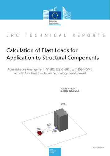
10. Underground BlastingTunnel design showinglifter delay allocationsA basic burn cut design and LP detonatorinitiation sequence (by numbers)
Underground Blasting Rules of ThumbProduction Blast ParametersDrill diameter (D) 16 Maximum hole length (m)Ring burden (B) 16 – 26 DHole toe spacing (parallel hole rings) 1 – 1.4 BHole toe spacing (radial hole rings) 1.4 – 2.0 BStemming length 15 – 25 DStemming rock size 10% DVoid ratio calculation Void Vol / Vol of rock x 100 (%)Void ratio required for rock swell 30 – 50%Max distance from blast holeto void hole in cut 2.5 x Void hole diameter ( 0.5 m)Diameter and number of relief holes for increasing blindraise length to increase probability of success:Raise Length (m)Hole Diameter(mm)510165456820034561520Blast TimingDelay between holes in cut 15 – 40 ms per m of hole length(Note: for blind long hole raise use upper limit)Delay between rings – Best throw 30 – 50 ms per m of burdenDelay between holes– Best fragmentation 2 – 6 ms per m of spacing10. Underground Blasting
10. Underground BlastingUnderground TroubleshootingExcess butts in the cut area – poor tunnel advance Review cut drilling to ensure holes are correct length and parallel. Review charging quality to ensure primers are located at the toe of theblast hole. Increase number or size of Void Holes in the Cut Area. Skip delay numbers to slow the cut initiation sequence. Reduce dimensions of the cut spacings 2.5 Void Diameter. Use lower density bulk explosive in the cut for better sensitivity.Excess butts in perimeter area (dishing) – poor tunneladvance Review drilling quality to ensure holes are parallel. Review charging quality to ensure primers are located at the toe of theblast hole. Review initiation sequence to ensure adequate relief (no tight corners). Use next delay in corners of the blast to allow for delay scatter. Reduce drill burdens/spacings to increase energy at the toe.Excess dishing of face – few butts evident / dogboxing ofcut Reduce drill burden/spacings from outer box. Review geology – reduce depth of burn. Reduce energy in Cut – low density products.Excess collar bridging, toe or lumpy floor Reduce uncharged collars in perimeter holes and/or the next row in. Review initiation timing to ensure adequate relief (no tight corners). Use next delay in corners of the blast to allow for delay scatter. Review number of lifters or explosives type for greater energy. Review product use for lifters i.e. incorrect product. Review charging practices.
Excess damage in perimeter – overbreak Review initiation sequence to ensure adequate relief (no tight corners). Review drilling pattern to reduce burden of the perimeter row. Reduce the perimeter (and/or next row) explosives energy per metre. Use low energy ANFO based products (Impact range). Use tailored energy bulk emulsion products (Subtek Control/low density). In stopes, allow extra delay of 15–40 ms for the last blasthole in each row.Leaving blast material behind – underbreak Review drill design for adequate breakout angle at toe ( 100 ) or sub drill. Review drill and blast design for adequate energy. Review initiation design for adequate relief to minimise confinement. Review primer positions and charging quality.Very large boulders in blasted material Review drill pattern for excessive burdens and spacings from deviation. Review boulders for blastholes, indicating cut-off explosive columns. Review initiation design for slow timing. Review boulders for source outside blast area – overbreak (see above).10. Underground Blasting
11. Conversion FactorsConversion FactorsThis unit Multiplied by Converts toLengthmetres (m)3.280feet (ft)39.370inches (in)kilometres (km)0.621miles (mi)inches (in)25.4millimetres (mm)Masskilogram (kg)2.20pound (lb)metric tonne (t)1.10short tonsounce (oz)28.35grams (g)ounce (troy)31.10grams (g)grains per ft0.2126grams per metreEnergyjoule (J)0.24calorie0.74ft-lbcalorie3.09ft-lbkilowatt (kW)1.34horsepower (hp)Volumecub. centimetres(cm3 or cc)0.06cub. metres (m3)1.31cubic yards (yd3)cubic feet (ft3)0.03cubic metres (m3)cubic inches (in3)US gallon3.79litres (l)Ounce (US fluid)29.57cubic cm (cm3)Converts to Divided by This unit
This unit Multiplied by Converts toDensitylbs/ft316.02kg/m3g/cm62.43lbs/ft33Powder 4.70psibar14.50psi100kPaTemperatureFahrenheit –320.56Celsius (ºC)Celsius 17.781.8Fahrenheit (ºF)Areacm20.16in22m1550.00in22ft0.09m2Converts to 11. Conversion FactorsDivided by This unit
12. Packaged ExplosivesDensity (g/cm3)Minimum VOD(km/sec)Cartridge countCase weight (kg)32 4001.164.56625Senatel Powersplit 26 25.2 m32 20.1 m32 25.2 m1.186.5115.31721.3Senatel Pyrosplit 32 25.2 m1.186.5121Senatel Pyromex 32 x 20032 x 70050 x 2204.7135385025ExplosivesApplicationCartridgediam length(mm)Properties of Senatel Special Use ExplosivesUG CoalSenatel Permitted1000SurfaceHot &Reactive*Hot &Reactive*1.16* The degree of heat and reactivity is determined by Orica standardtemperature and reactive ore tests.Senatel Permitted 1000Senatel Powersplit Senatel Pyrosplit Senatel Pyromex
1393.4Senatel Magnum 1.232011533.4Case weight (kg)Minimum VOD (km/s)183Cartridge countREE Bulk Strength(% ANFO at 0.95 g/cc)1.21Nominal Cartridge Diam/Length (mm)REE Bulk Strength(% ANFO at 0.8 g/cc)Senatel Powerfrag ExplosivesNominal Density (g/cc)Packaged EmulsionExplosives Properties32 20032 70045 40055 30065 30080 40025 20025 70032 20032 1 Only fragmentation energy is quoted for packaged explosives becausethe current detonation codes cannot accurately model the effects of airdecoupling on heave energy.2 Fragmentation energy and heave energy are quoted for bulk explosivesin the previous tables.Senatel Powerfrag Senatel Magnum 12. Packaged Explosives
13. Initiating SystemsExel Non-Electric InitiationExel Non-Electric DetonatorsLP SeriesDelayNo.J HookColourFiringtimes 04500115500126500137500148500159500MS 00900100011001100DelayFiringNo. times 50505050100
Exel Enduradet Extended Millisecond RangeNon-Electric DetonatorsDelayNo.Firingtimes 52525252550505050505010010010010013. Initiating SystemsDelayNo.Firingtimes 00400450450500500550650700800
13. Initiating SystemsProperties of Exel DetonatorsProductDetonatorPETN Mass (g)Delay RangeTubeColourLeadLengths (m)PETN 7909 – 600 msOrange 7.2, 9, 12,3.6, 6,Exel Millisecond (MS)15,18, 243.6, 4.9,6.1, 24Exel Long Period (LP)PETN 79025 – 9600 msYellowExel Enduradet PETN 79025 – 8050 msRed9, 12, 15,18, 24,30, 36, 45,Exel Bunchdet PETN 480600 msPink1, 6Exel HandidetPETN 79025 ms(surface)/400 ms in3.6, 6.1,Yellow 9,12,18,24Not all lengths are part of the standard offeringExel MillisecondDetonatorsExel BunchdetExel LongPeriod DetonatorsExel Handidet DetonatorsExel Enduradet Detonators
Exel Surface Initiation ConnectorsNominal Time (ms)Block ColourTube OrangeCreamMustardLime GreenPinkExel signal tube (3 mm OD)Standard length – 3.6, 4.8, 6.0, 9, 12, 15, 18Exel Connectadet Detonators13. Initiating Systems
13. Initiating SystemsExel Surface IntiationConnectorsExel Millisecond ConnectorsNominal Delay Time (ms)Cleat Colour9Green17Yellow25Red35Pink42White65BlueYellow Exel signal tube (3 mm OD) Total length 80 cmTypeExel Lead in LineExel Connectaline Exel Lead in LineStandardLength (m)DetonatorPETN charge (g)60, 3000.45 (#8 Strength)700N/AExel Connectaline
Properties of Pentex BoostersBooster mm)NominalMass (g)ShellColourPentex D1.5 – 1.656.52125OrangePentex G1.77.231110PinkPentex entex PPP1.77.255400OrangePentexPowerPlus 9001.77.280900RedPentexStopeprime 1.77.241250Yellow432Yellow /Green Cap Pentex G L1.67.253From left:Pentex H, Pentex D, Pentex G, Pentex Stopeprime , Pentex G L, Pentex PP900, Pentex PPP13. Initiating Systems
13. Initiating SystemsPentex BoostersRecommendedfor Hole Diameter/Explosive CombinationsHole Diameter (mm)Product384564ANFO7689102115160200300Pentex Stopeprime Pentex GPentex G L / PPPPentex HPentex proTECT-ePentex PP900Fortis Pentex G L / PPPPentex HPentex proTECT-ePentex PP900FortanPentex G L / PPP Pentex HPentex proTECT-ePentex PP900Flexigel Pentex G L / PPPPentex HPentex proTECT-ePentex PP900Aquacharge Pentex G L / PPPPentex HPentex proTECT-ePentex PP900Table continues below
Hole Diameter (mm)Product384564Subtek 7689102115160200300Pentex Stopeprime Pentex GPentex G L / PPPPentex HPentex proTECT-ePentex D Pentex PP900Civec Pentex Stopeprime Pentex GPentex G L / PPPPentex HPentex proTECT-ePentex D Pentex PP900CentraPentex G L / PPP Pentex HPentex proTECT-ePentex PP900Vistis Pentex G L / PPPPentex HPentex proTECT-ePentex PP900VistanPentex G L / PPP Pentex HPentex proTECT-ePentex PP90013. Initiating Systems
13. Initiating SystemsCordtex NominalDetonating CordsNominal MaximumCord TypeCoreload ordtex 4.3W4.32505006.5 – 7.04.080ºCOrangetwo blackstripesCordtex XTL NC103005.5 – 6.04.680ºCYellowCordtexPyrocord 103506.5 – 7.04.6100ºCOrange Cordtex 4.3WCordtex XTL NCCordtex Pyrocord
Lead in LineMS & LP DetonatorEnduradet MSCConnectadet Handidet Bunchdet (Surface)Cordtex 4.3WCordtex XTL NCPentex DPentex GPentex HPentex G L / PPPPentex PP900Pentex proTECT-ePentex Stopeprime Combinations of Detonators,Detonating Cords and BoostersYYYNYYYYYYYYYYNYeDev IIYYYNYYYYYYYYYYNYi-kon IIIYYYNYYYYYYYYYYYYuni tronic 600YYYNYYYYYYYYYYYYLead in LineYYYNYYYYYNNNNNNNMS & LP DetonatorYYYNYYYYYYYYYYNYEnduradet YYYNYYYYYYYYYYNYMillisecond Connector DetonatorElectric Instantaneous IIElectronic DetonatorExel Connectadet Handidet Bunchdet (Surface)Note: Handidet should be considered as Connectadet orMS detonator, depending on the donor/receptor combinationbeing applied.YYYNYYYYYNNNNNNNDetonating CordCordtex 4.3WYYYYYNYYYNNNYYNNCordtex XTL NCNNNYNNNYYNYYYYNYCompatibility tables should be read in conjunction with all relevant Technical DataSheets. Disclaimers contained within these Technical Data Sheets will apply.13. Initiating Systems
14. Electronic Blasting Systemsuni tronic 600ApplicationApplicationKey BenefitsSmall surfacemines andquarries Quick on-bench diagnostics via on-bench testability. Quick hook-up on blast day via new connector andduplex wire. Improved resistance to leakage via new ApplicationSpecific Integrated Circuit (ASIC) and Printed CircuitBoard (PCB). Improved precision. Improved reliability via 6 Sigma target. More robust communications. New safety features in electronics. Improved packaging. Help for blaster via length encoded ID number.uni tronic 600Fully programmable from 0 msto 10,000 ms in 1 ms incrementsRemote firing available for open cut applications.915202530Downline wireWire length (m)Delay timesTypeTechnical PropertiesCopperclad steel
Blast Box 310/310RScanner 200The Blast Box provides the voltageand command to fire the detonatorsin programmed sequence. The 310R(pictured) offers remote firing capability.The Scanner 200 scans unique IDnumbers on the detonators and allowsthe functionality of each detonatorin the pattern to be tested before thebench is cleared.SHOTPlus Blast Design Softwareuni tronic 600 DetonatorOrica’s SHOTPlus Blast Design Softwaregives printed blast plans, useful on thebench with the uni tronic 600 system.Accurate and fully programmableelectronic detonator.uni tronic 600 ConnectorDuplex Harness WireDesigned for on-bench efficiency,the connector carries signals betweenthe detonator and the harness wire.Faster and easier to
POCKET BLAST GUIDE. Risk Matrix Decision A Stop, Get Supervisor, JSERA B Stop, JSERA C Contin