Transcription
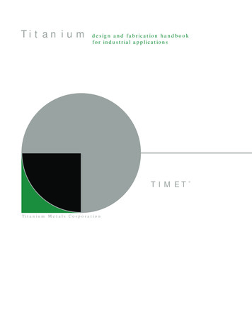
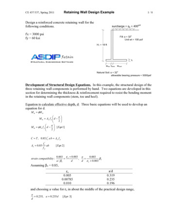
To appear in ACM TOG 4(33).Design and Fabrication by ExampleAdriana Schulz1 Ariel Shamir2 David I. W. Levin1 Pitchaya Sitthi-amorn1 Wojciech Matusik11 Massachusetts Institute of Technology 2 The Interdisciplinary Center Herzliya Figure 1: The design and fabrication by example pipeline: casual users design new models by composing parts from a database of fabricabletemplates. The system assists the users in this task by automatically aligning parts and assigning appropriate connectors. The output of thesystem is a detailed model that includes all components necessary for fabrication.AbstractData-driven methods have previously been used to make geometricdesign easier and therefore more accessible to non-experts.In the “modeling by example” approach, first presented byFunkhouser and colleagues [Funkhouser et al. 2004], new objectsare constructed by assembling components of existing objectsin a database. This allows even novice users to model complex3D geometry. However, in creating fabricable designs, severalchallenges arise that have not been addressed in the previousresearch. First, all the components in the example database must befabricable. Second, any manipulation applied to these componentsmust preserve structure and manufacturability. Third, standardcomputer graphics techniques such as mesh blending cannot beapplied to connect and assemble components. In order to combineparts, these parts must be accurately positioned, and real connectors(e.g., screws or hinges) must be used. The best choice of connectorswill depend on the geometric, functional, and material properties ofthe object. Finally, the resulting model must be structurally sound,so that once it is built it will not topple or collapse.We propose a data-driven method for designing 3D models that canbe fabricated. First, our approach converts a collection of expertcreated designs to a dataset of parameterized design templates thatincludes all information necessary for fabrication. The templatesare then used in an interactive design system to create new fabricable models in a design-by-example manner. A simple interfaceallows novice users to choose template parts from the database,change their parameters, and combine them to create new models. Using the information in the template database, the systemcan automatically position, align, and connect parts: the systemaccomplishes this by adjusting parameters, adding appropriate constraints, and assigning connectors. This process ensures that thecreated models can be fabricated, saves the user from many tediousbut necessary tasks, and makes it possible for non-experts to designand create actual physical objects. To demonstrate our data-drivenmethod, we present several examples of complex functional objectsthat we designed and manufactured using our system.In this work, we present an interactive design-by-example system for fabrication that addresses these challenges. To build thedatabase of examples, we have worked with domain experts to create a representative set of example designs for several categories ofobjects. Each design is modeled using a commercial CAD softwareand is composed of a collection of standard parts that can be purchased from suppliers. It also includes all assembly details such asconnectors and support structures, ensuring the object is fabricable.We automatically convert these specific designs to parameterizedtemplates by extracting constraints and parameters from the models. This allows us to perform structure–preserving manipulationsusing both discrete and continuous parameters of the parts. Thetemplate representation is hierarchical and includes connectivityconstraints between parts.CR Categories: I.3.5 [Computer Graphics]: Computational Geometry and Object Modeling—Geometric algorithms, languages,and systems I.3.8 [Computer Graphics]: ApplicationsKeywords: fabrication, data-driven methods, design1IntroductionWe are approaching a time when ordinary people can fabricate theirown 3D objects and products. However, to fabricate an object onefirst needs to design it. Currently, only experienced experts possess the knowledge and design skills to build complex, functionalobjects. This is because creating an object that can actually be fabricated involves more than just designing its shape. How shouldthe parts be connected? Is the design stable and sturdy? Are theparts available for purchase or even affordable? In this work, wepropose a data-driven method that addresses these and other designchallenges, allowing non-experts to design and fabricate complexobjects.Using the dataset of templates and information extracted fromthem, we create an assembly-based modeling system for noviceusers. The user can pick and drag substructures from different designs and add them to a working model. The system guides the userthrough the snapping and connecting stages. Snapping involvesautomatically positioning the parts relative to each other, and selecting template parameters of the new parts to allow connectivity andalignment. Connecting involves automatically selecting the appropriate components and connectors that should be added to hold the1
To appear in ACM TOG 4(33).regular patterns. Like Bokeloh et al. [2012], we construct a linearmodel that allows us to express the space spanned by all possiblemanipulations as a parameterized model. Our templates possesstwo additional qualities that are essential for our application. First,they follow a hierarchical tree structure that allows assembly ofnew models by composing substructures at different levels of thetree. Second, they encode information that guarantees fabricability.For example, we represent how parts connect to each other in thephysical world, and we allow parts to be resized only if a corresponding physical process is possible. Our template representationis discussed in detail in Section 3.2.parts together. Our system also includes a physics-based simulationcomponent that can evaluate the stability of the composed model,highlighting unstable parts in the design. This relieves users frommany tedious and complex tasks that are nevertheless necessary forfeasible fabrication of the models, allowing them to concentrate onthe creative process.To the best of our knowledge, we are the first to propose a completedata-driven system for digital fabrication. In addition to the system,our work contains the following technical contributions: A hierarchical template representation for fabricable designsand a method for automatically converting fabricable designs totemplates (Sections 3.2 ) An efficient method for snapping fabricable templates together(Section 4.4), An efficient method for connecting parts that guarantees manufacturability (Section 4.5).Fabrication-aware Design Digital, personalized fabrication hasgarnered a lot of interest in the computer graphics community. ThePlushie system by Mori and Igarashi [2007] allows non-experts toconvert 3D models to physical plush toys. Saul et al. [2011] proposean interactive system for sketching chair models that can easily befabricated. More recently, Chen et al. [2013a] and Hildebrand etal. [2012] have proposed systems to convert 3D models to simplified, fabricable designs consisting of interlocking planar pieces.Schwartzburg and Pauly [2013] extend these ideas by developing aninteractive design system that employs optimization and structureanalysis to provide instant feedback to users. Similarly, Umetaniet al.[2012] build an interactive system for furniture design thatis tightly coupled with a physically-based simulation in order tocorrect invalid designs and provide users with design suggestions.Finally, Lau and colleagues [2011] suggest a method for generating the parts and connectors needed to convert a 3D model into aphysical object. This work focuses on furniture models and definesa formal grammar for IKEA tables and cabinets.To illustrate the generality of our data-driven method, we have usedthe system to design and fabricate a variety of different objects,from furniture to go-karts. We are also releasing a database ofparameterized fabricable models, which we believe will be an invaluable resource for future work in this research area.2Related WorkOur work employs methods in data-driven modeling, shape manipulation, and fabrication-aware design.Modeling by Example Shape collections have been widely usedto allow data-driven geometric modeling. Modeling by example [Funkhouser et al. 2004] enables the design of new models bycombining parts of different shapes from a large database. Morerecent work focuses on data-driven suggestions for adding details [Chaudhuri and Koltun 2010] and modeling [Chaudhuri et al.2011]. Similarly, recombination of model parts has been used toexpand databases [Kalogerakis et al. 2012; Jain et al. 2012] andrepair low-quality 3D models [Shen et al. 2012]. Nevertheless,none of this research explores the fabrication aspect of data drivenmodeling. Creating models that can be physically realized adds anumber of challenges to the modeling pipeline that are addressed inthis work.There has also been work in the computer-aided design community related to creating fabricable designs from user input. Roy etal. [2001] provide a natural language specification and iterative design process that transforms a simple functional specification intoa detailed design. Chiou et al. [1999] use a small set of primitives and an accompanying matrix decomposition to accomplish thesame task. Finally Gui and Mäntylä [1994] provide a sketch-basedsystem for mechanical design.The main difference between our approach and the previous workis that we are the first to propose a data-driven method for fabrication. In data-driven methods, production rules are implied bythe dataset and they do not have to be explicitly distilled. It is thisfeature that motivates our data-driven approach. In our work, weillustrate the expressive power of data-driven methods by using thesame algorithm to build furniture and go karts.Template-based Shape Manipulations Many previously developed tools exist for the geometric editing of man-made shapes.Kraevoy et al.[2008] present a method for shape-aware resizingof man-made objects that can be non-uniformly scaled along threemain axes. Our work is also related to the iWires system [Gal et al.2009], which preserves structural relationships during editing usingconstrained non-linear optimization. Similarly, Zheng et al.[2011]segment a man-made shape and associate a controller with eachcomponent. The shapes of individual parts can be changed whilepreserving the structural constraints. The work by Xu et al. [2011]employs a similar strategy but uses an image as an input. Othershape manipulation methods that work with discrete variations(e.g., component repetitions) have been explored [Bokeloh et al.2011; Lin et al. 2011; Bokeloh et al. 2012]. Finally, recent work[Ovsjanikov et al. 2011; Kim et al. 2013] explores the creation anduse of parameterized templates in order to explore shape collections.3A Database of Fabricable TemplatesOur system relies on a database of fabricable templates. The usercan pick templates from the database, modify their parameters, andassemble them to create new designs. To build this database, wefirst collect fabricable models and then convert these designs to ahierarchical template representation.3.1Collecting Fabricable ModelsTo the best of our knowledge, no available repository of 3D modelscontains the necessary information for fabrication. We have therefore gathered a collection of fabricable models with the help ofdesign experts—in this case, a group of mechanical engineers. Thedata is divided into two sections: an items catalog containing a listof commercial items, and a set of designs constructed by domainexperts. Each part used in a design references a corresponding itemin the catalog. This imbues our data with the unique property thatall the designs can actually be manufactured. The data is availableat http://fabbyexample.csail.mit.edu.In our work, we create a parametrized template representation formanipulating shapes inspired by two classes of methods. The firstclass preserves global relationships [Gal et al. 2009; Zheng et al.2011] but only considers continuous variations in the shape. Thesecond class allows discrete variations [Bokeloh et al. 2012] butonly accounts for local relationships. We combine these two ideasto construct models that both preserve global relationships suchas symmetry and perform topological changes to preserve discrete2
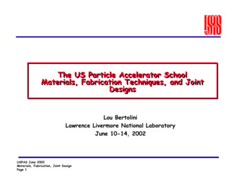
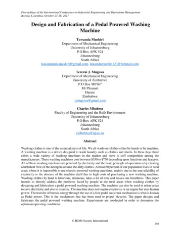
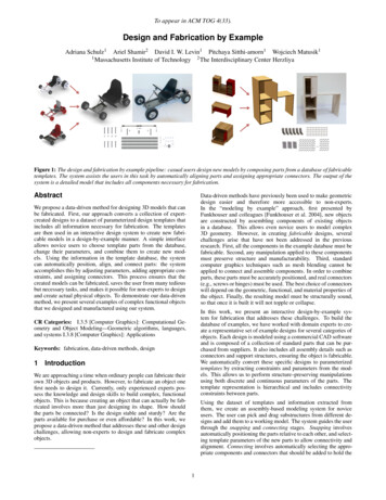
To appear in ACM TOG 4(33).Items CatalogRef# 1789A25 5.69Ref# 90198A105 7.38/100Ref# 1057A51 25.61Ref# 90198A10512”X12”: 7.3812”X24”: 13:5424”x24”: 24.62Figure 2: An example of a fabricable object from our collection(left). Each design is detailed down to the level of individual screws,and each part maintains a reference to the items used from the itemscatalog (right).Figure 3: An example of a template. The original design is shownin gray, and new designs generated by varying the template parameters are shown in yellow.porating information on how elements connect to each other in thephysical space.Items Catalog An item is a physical part that can be purchasedfrom a variety of suppliers or manufacturers. The items catalog liststhe available items along with all information required for their useduring the design and fabrication process: their corresponding material type (e.g., wood, metal, glass), their price, their dimensions,and a 3D mesh representing their geometry.Hierarchical Template Representation. We define a template asa part of a design that can be manipulated in a structure-preservingfashion. Templates provide a number of free parameters which canbe used to manipulate associated geometry. An example of a singletemplate is depicted in Figure 3. The figure illustrates the largeamount of geometric variety that a single template can encode: inthe figure, a cabinet becomes everything from a workbench to anightstand.The items within the catalog incorporate two additional pieces ofinformation that are used in later stages of our method. First, eachdimension of an item is labelled as either fixed or resizable. Weonly allow resizing of items if a corresponding physical process ispossible. For example, we allow resizing of wooden componentsbecause they may be cut using available tools. This informationis used during the design parameterization process. Second, eachitem maintains links to external suppliers (e.g., McMaster-Carr),allowing for easy sourcing during fabrication.More formally, a template at the ith level of the template hierarchyT i can be written as T i qi , A i , F i(1)where qi are the degrees of freedom for the template; F i is a deformation function that, given qi , computes new geometry; and A i isthe feasible space of qi , which is chosen to ensure that the geometryproduced by a template remains fabricable and collision-free.Set of Designs The design set contains a large number of manufacturable models (henceforth called designs) created using commercial CAD software (Solidworks). Each design is an assemblyof parts, and the parts all contain links to the corresponding itemsin the items catalog (Figure 2). The parts are grouped into subassemblies in a hierarchical fashion, as is common in standard CADtools. Once a design has been finalized, we build an associatedconnectivity graph, where nodes represent parts and edges indicatephysical connectivity between them. We create this graph automatically based on the proximity of parts.We convert each design to a template tree, following the hierarchical representation determined by the experts. For each leaf node,we explicitly define qi and F i , and we define A i based on the set ofconstraints that act on qi . For the internal nodes, we specify qi andF i as the composition of the children nodes. The feasible set on aninternal node can be defined as the intersection of the feasible setsof its children restricted by additional “coupling constraints” thatbind multiple templates together.Designs often feature complex moving parts connected by mechanical joints. Such connections are used in various doors and drawers,and in complex moving objects like swings, wheels and steeringassemblies. We rely on the experts to annotate their designs withthis functionality if it exists. We store moving components in thestandard way: as a hierarchy of joint transforms along with theirrespective joint types (prismatic, ball joint, hinge joint) and jointlimits.Template Construction. Our method for automatically converting a design from the collection to a template comprises two steps.First, we select the leaf nodes and assign their degrees of freedom qi and deformation functions F i . Second, we analyze thesemantic geometric (geosemantic [Shtof et al. 2013]) relationshipsbetween parts of our model in order to define structure-preservingconstraints at each level of the hierarchy, thus determining A i (seeexample in Figure 5).Domain experts also annotate parts that are purely structural (e.g.,screws, hinges and brackets), henceforth called connecting parts.The connecting parts are separated from the principal parts of thedesign (e.g., shelves, legs, wheels) since the connecting parts willnot be used explicitly in the design-by-example process. Instead,we relieve the user from the tedious task of specifying them byinferring and adding them automatically during the design process(see Section 4.5).We use the hierarchical structure of a design to guide the construction of the template tree. In most cases, we assign each part Piin the design to be a leaf-node. We then choose qi to be the 6vector composed of the 3-dimensional position of the center of thepart and the three axis-aligned scaling parameters. The deformationfunction F i simply applies the prescribed scale and translation to Pi .3.2We also allow leaf nodes to represent repeating patterns of parts(Figure 4). We automatically search the design for repeating patterns and group them in a single leaf node. Although we can stillrepresent qi as the 6-vector that describes the scaling and translation of the pattern, the deformation function F i is slightly morecomplex. Details of this process are given in Appendix A.Parameterized TemplatesOnce we have the input collection of fabricable models, we create a template representation of the designs that allows structurepreserving manipulations and part recombination. First, we convertthe designs into hierarchical parameterized representations whichwe call templates. Then, we augment this representation by incor-In our template model, a leaf-node in the template tree serves as a“least-fabricable-unit”, the simplest single entity that can be constructed. Leaf-nodes play a crucial role in the remainder of our3
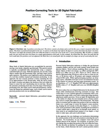
To appear in ACM TOG 4(33).C0wagonC1handleC2bodyconn 1C3wheelC4bucketconn 2conn 2conn 1Figure 5: From left to right: a design example of a toy wagon, the hierarchical template tree, and a visualization of the connections. Thearrow on the handle indicates that this part has an articulation, namely that it can rotate along the depicted axis. The template tree includesthe geosemantic relationships that are stored at each level of the hierarchy, C0 to C4 (shown in blue), as well as connections (depicted in red).The vizualization on the right illustrates the information contained in each connection node.straints on each element (C1 , C3 , and C4 ). The body assembly storesthe coplanarity and concentricity relationships between the wheeland the bucket (C2 ). Finally, the root node stores the coplanarityrelationships between the handle and the bucket (C0 ). Notice thatthe handle has an articulation; therefore, we compute relationshipsin both the horizontal and vertical rest configurations.We characterize geosemantic relationships as functions that act onthe bounding box or prominent planes of each element. In mostcases, we choose the six planes that define the bounding box to bethe prominent planes. Since both the box and the planes are determined by qi , each geosemantic relationship can be expressed as alinear equality or inequality that constrains q. For more details onhow to find these relationships and express them as linear equations,please refer to Appendix B. Since we store the geosemantic relationships hierarchically, we can construct a linear system at eachnode T i by aggregating the constraints of all its children. The feasible set A i is then the set of all solutions to that linear system. Notethat all of these relationships are computed automatically based onthe geometry of the original design and the annotations on the inputdata.Figure 4: A template with pattern elements. Upon resizing, boththe number of floor planks and the number of rungs in the monkeybars change.algorithm, and are therefore referred to as elements to clearly distinguish them from the internal nodes of the template hierarchy.Elements that correspond to principal parts are called principal elements, while elements that correspond to connecting parts are calledconnecting elements.Connections. Fabrication requires not only tracking abstract geometric constraints, but also understanding where and how elementsconnect to each other in the physical world. To accomplish this,we augment our template representation with nodes that keep trackof the physical contact and connections between the principal elements. We represent these relationships as connection nodes. Connections include references to the data that will be manipulated andcarried over when combining elements to compose a new model.These includeTo define A i , we constrain the space of template variations by extracting geosemantic relationships from the design and ensuringthat they are preserved when the template parameters qi are manipulated. Following the ideas described in [Gal et al. 2009; Zhenget al. 2011; Chen et al. 2013b], we take into account the followingtypes of relationships between elements: concentricity, coplanarity,and symmetry. In addition, we consider relationships in the orderof the elements. Preserving order relationships guarantees that elements do not penetrate each other or exchange position when thetemplate parameters are modified. the set of principal elements that are in contact (usually two butsometimes more), the set of connecting elements that are responsible for holdingthe principal elements together,We also extract geosemantic relationships guided by experts’ annotations. First, we take into account the articulation informationto ensure that all geosemantic relationships hold for all design configurations. Specifically, we consider the poses in which articulatedparts reach their joint limits. Second, we take into account the physical properties of elements in the design using information from thecorresponding items in the items catalog. For example, we constrain the scaling parameters of elements that are linked to itemsthat cannot be resized in a certain dimension. the set of geosemantic relationships between the connecting elements and the principal elements, and a set of “soft” geosemantic relationships for placement of connecting elements (discussed below).Grouping the elements into such structures is straightforward andcan be achieved by directly analyzing the connectivity graph ofthe design described in Section 3.1. The set of “soft” relationshipsencode additional constraints on the connecting elements. At eachconnection, we compute the contact of the principal elements (thecontact patch), and we add linear constraints to ensure that thedimensions and position of the connecting elements are preservedwith respect to this contact patch . When the designer manipulates the template by changing the parameters of the principal el-The geosemantic relations are stored in the hierarchy at the lowestinternal node that is a parent of all the related elements. This allowsthe use of any sub-tree in the hierarchy as a template by itself sinceits defining relations are self-contained. Consider, for example, thetoy wagon in Figure 5. The template leaf-nodes store scaling con-4
To appear in ACM TOG 4(33).ements, the parameters of the connecting elements are optimizedusing these additional relationships as soft constraints. This relievesthe designer from the tedious task of manipulating each connectingelement individually.Composition in a fabrication-aware system is difficult becauseone cannot merely apply simple geometric operations to mergeparts. To combine two substructures, the substructures must be perfectly fitted and aligned, and appropriate connecting elements (e.g.,screws and hinges) need to be added between them. This process isnot only tedious, but sometimes impossible for users who lack thenecessary expertise.Like geosemantic relationships, connections are stored on the lowest internal node that is a parent of all the principal elements theyreference. In the example of Figure 5, we have two connections.One connects the handle to the bucket and is stored in the root nodeof the toy wagon; the other connects the bucket to the wheel and isstored in the internal node that groups the body assembly.Our system addresses these difficulties with two crucial operationalfeatures. First, when a user drags in a new component and dropsit onto the scene, the system automatically uses information storedin the database to adjust the component’s position and size so thatit fits and aligns with the working model. We call this proceduresnapping. The snapping operation optimizes the component’s position and size based on the position in which the user dropped thecomponent and the component’s current dimensions. If the user isnot satisfied with the snapped configuration, the user can edit thecomponent (through template manipulations) and drag it around thescene, and the snapping procedure will then automatically computethe component’s new optimal position and size.Constructing the template hierarchy in this manner ensures thateach node in the hierarchy is a complete representation that dependsonly on its children. Therefore, the database of templates that weconstruct includes not only full models of the original design (rootnodes) but also all the other nodes in each hierarchy, representing parts and sub-structures. The result is a much richer databasethat supports the design-by-example mechanism of assembling newmodels by composition of templates representing parts at variouslevels.4Second, our algorithm automatically retrieves new connecting elements that attach the added component to the working model.This is achieved by searching the database for similar examples ofconnections. During this process, we compute new geosemanticrelationships between the added template and the working model.Both the new connecting elements and the new geosemantic relationshops are added to the hierarchy of the working model togetherwith the added component. We call this process connecting.ModelingIn this section we outline the design workflow of our system anddescribe in technical detail the system’s main operational features.4.1Design WorkflowOur system is based on the design-by-example workflow[Funkhouser et al. 2004; Chaudhuri and Koltun 2010]. Figure 6illustrates our user interface. Icons that link to components of thedatabase are displayed on the left; and the canvas on the right isused to design a new model, henceforth called the working model.Users compose parts by dragging them onto the scene, and theycan also remove selected parts at any level of the hierarchy.4.2Template ManipulationsAllowing users to manipulate template parameters adds variety tothe designs (see Figure 3) and allows fitting parts of different sizes.Adjusting template parameters modifies a design’s shape and dimensions, but preserves its overall structure. This method of template manipulation guarantees that the composed models are fabricable.We allow template parameters to be manipulated at all levels of ourhierarchical structure. The user can select elements (leaf nodes)by clicking on them, and then traverse up the hierarchy to selectinternal template nodes. When a template node is selected, controlsfor scaling and translation are revealed (see Figure 7). At each levelof the hierarchy, the controls act on the bounding box of the selected template. Therefore, the user can make higher-level changesby selecting internal nodes and make more detailed adjustments byselecting leaf nodes.Template parameter manipulation is not an unconstrained procedure. A given template is restricted to the feasible space A storedat the root node of the hierarchy. As outlined in Section 3.2, wedefine the parameters of the root node q as the stacked vectorof all the children qi . We can then represent all linear, geosemantic constraints (bilateral and unilateral) in the standard form:Aq b, Gq 0. We augment A with constraints that fix the centerof the model in order to prevent translation of the edited template.Figure 6: The user interface. Icons that link to components of thedatabase are displayed on the left, and the modeling canvas is onthe right.As we explained in Section 3.2, the components of the databaseare hierarchical parametrized templates. This allows us to composemodels from different designs at different levels, i.e., we can addand remove small components (e.g., a single shelf), medium components (e.g., a drawer), and large complex ones (e.g., an entirecabinet). When creating a new model, we can either start fromscratch or work from an existing design.To create the controls we use six functions c j , such that the cTj q correspond to the center and dimensions of the axis-aligned boundingbox. When manipulating leaf nodes, the c j are standard basis vectors, since qi defines the axis-aligned bounding box of the element.For larger substructures represented by internal nodes, we first compare the bounds of the children elements to determine which onesconstrain the bounding box of the
et al.[2012] build an interactive system for furniture design that is tightly coupled with a physically-based simulation in order to correct invalid designs and provide users with design suggestions. Finally, Lau and colleagues [2011] suggest a method for generat-ing the parts and connec