Transcription
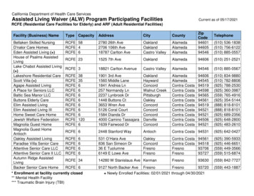
F-16 ARFAssembly ManualSpecificationsWingspan:Length:Wing Area:Weight w/o Battery:Weight w/Battery:28 in (709mm)35.5 in (900mm)195 sq in (12.6 sq dm)18–20 oz (510–567 g)23.5–25.5 oz (667–723 g)LOCKHEED MARTIN, F-16, associated emblems and logos, andbody designs of vehicles are either registered trademarks ortrademarks of Lockheed Martin Corporation in the USA and/orother jurisdictions, used under license by Horizon Hobby, Inc.
Table of ContentsIntroduction. 2Using the Manual. 2Contents of Kit/Parts Layout. 2Recommended Radio Equipment. 3Optional Accessories. 3Required Tools and Adhesives. 3Required Speed Control and Battery. 3Notes Regarding Servos and ESC. 3Note on Lithium Polymer Batteries. 3Warning. 3Wing and Stabilizer Installation. 4Elevator and Aileron Servo Installation. 6Landing Gear Installation. 9Speed Control and Receiver Installation. 13Vertical and Ventral Fin Installation. 15Motor Battery Installation. 16Missile Installation (Optional). 17Removing Fan and Motor forServicing or Replacement. 17Radio Programming. 18Control Throws. 19Center of Gravity. 20Preflight. 20Range Test Your Radio. 20Flying Your F-16. 21Safety, Precautions, and Warnings. 21Warranty Information. 21Instructions for Disposal of WEEE byUsers in the European Union. 222008 OfficialAcademy of ModelAeronautics Safety Code. 23IntroductionThe F-16 Fighting Falcon was originally designedin 1971 to be a multi-role fighter in both air-to-aircombat and air-to-surface attacks. Today the F-16 isknown for its amazing maneuverability, precision strikeand attack capabilities and speed. The F-16’s versatilityallows it to be equipped with a variety of weapons,including missiles or bombs. The Fighting Falconis still in use today and is currently serving manycountries. The USAF uses F-16s in their Thunderbirddemonstrations.Contents of Kit/Parts LayoutReplacement 7082EFL7083Fan Unit w/MotorCanopy/HatchStabilizer SetExhaust Nozzle and Nose ConeMissiles and Launch RailsLanding Gear Set w/HardwareGear Doors and Ventral FinsPushrod KitE-flite’s F-16 400 DF (ducted fan) is designed toreplicate the full-scale F-16 as a performance sportscale model. Constructed of lightweight, durableinjection molded foam, the F-16 is beautifully finishedwith a highly visible USAF Thunderbirds trim scheme.The F-16 400 DF also includes molded panel lines andcustom applied decals for added scale appearance.It is highly prefabricated with molded servo pockets,prehinged flight surfaces, a magnetic battery hatchand the included and installed motor and fan unit toget you in the air faster.The F-16 is capable of smooth, aerobatic maneuverssure to please any crowd and the USAF Thunderbirdstrim scheme will make all of your friends jealous. TheE-flite F-16 400 DF will offer the ambitious sport scalemodeler just the thrill he’s been looking for.Using the ManualThis manual is divided into sections to help makeassembly easier to understand, and to provide breaksbetween each major section. In addition, check boxeshave been placed next to each step to keep trackof its completion. Steps with a single circle ( ) areperformed once, while steps with two circles ( )indicate that the step will require repeating, such as fora right or left wing panel, two servos, etc.Remember to take your time and follow the directions.The Spektrum trademark is used with permissionof Bachmann Industries, Inc.2E-flite F-16 ARF Assembly Manual
Recommended Radio EquipmentYou will need a minimum 4-channel transmitter,receiver, and four or five servos (if using nose gearsteering). You can choose to purchase a completeradio system. If you are using an existing transmitter,just purchase the other required equipment separately.We recommend the crystal-free, interference-freeSpektrum DX6i 2.4GHz DSM 6-channel system. Ifusing your own transmitter, we recommend the E-fliteS60 Super Sub-Micro servos .If you own the Spektrum DX6i radio, just addthe AR6200 DSM2 6-channel receiver and fouror five (nose gear steering) E-flite S60 SuperSub-Micro servos.Complete Radio SystemSPM6600DX6i DSM2 6CH systemOr Purchase SeparatelySPMAR6200 AR6200 DSM2 6-Channel FullRange Receiver (for DX6i orDX7)AndEFLRS60 S60 Super Sub-Micro Servo (4,5 if using nose gear steering)EFLREX3L3-inch Extension, Lightweight (2)EFLREX9L9-inch Extension, Lightweight (2)Note: If you are not using a computer radio,you will be required to purchase the followingitems:EFLRYH33-inch Y-Harness, LightweightEXRA320 Y-Harness 6-inch/ReverserStandardOptional AccessoriesEFLA110Power MeterEFLC3005 Celectra 1- to 3-CellLi-Po ChargerEFLC505 Intelligent 1- to 5-CellBalancing ChargerRequired Tools and AdhesivesTools & EquipmentMixing sticksRubbing alcoholDental flossPin drillSandpaperPhillips screwdriver:Paper towelsMixing cupsHobby knife (#11 blade)Drill bit: 5/64-inch (2mm)Epoxy brushes#00, #1AdhesivesThreadlock6-Minute Epoxy (HAN8000)Medium CA (optional for missile installation)Required Speed Control and BatteryEFLA102525-Amp Pro Brushless ESCTHP21003SPL 2100mAh 3-Cell 11.1V LiPo,16GANotes Regarding Servos and ESCWARNING: Use of servos other than those we suggestmay overload the BEC of the recommended ElectronicSpeed Control (ESC). Please use only the servos listedwhen utilizing the recommended ESC’s BEC, or the useof a separate BEC (like the UBEC) or receiver batterypack when using other servos.Note on Lithium Polymer BatteriesLithium Polymer batteries are significantlymore volatile than alkaline or Ni-Cd/Ni-MH batteries used in RC applications.All manufacturer’s instructions and warningsmust be followed closely. Mishandling ofLi-Po batteries can result in fire. Alwaysfollow the manufacturer’s instructions whendisposing of Lithium Polymer batteries.WarningAn RC aircraft is not a toy! If misused, it can causeserious bodily harm and damage to property. Flyonly in open areas, preferably at AMA (Academy ofModel Aeronautics) approved flying sites, following allinstructions included with your radio.Keep loose items that can get entangled in thepropeller away from the prop, including loose clothing,or other objects such as pencils and screwdrivers.Especially keep your hands away from the propeller.During the course of building your F-16 we suggestthat you use a soft base for the building surface.Such things as a foam stand, large piece of beddingfoam or a thick bath towel will work well and helpprotect the model from damage during assembly.We recommend the use of our E-flite 25-Amp ProBrushless ESC (EFLA1025). You will notice that themanual for the ESC recommends the use of only 4servos while using the BEC. The F-16 uses 5 servoswith the optional nose gear steering. We have testedthis setup and due to the low usage and current drawof this nose gear steering servo, the ESC is capable ofoperating with the BEC under this condition.E-flite F-16 ARF Assembly Manual3
Wing and Stabilizer InstallationRequired PartsFuselageWing panel (right and left)Stabilizer (right and left)2mm x 12mm self-tapping screw (4)Required Tools and Adhesives6-minute epoxyMixing cupMixing stickEpoxy brushPaper towelRubbing alcoholSandpaperPhillips screwdriver: #1During the manufacturing process it is possible that aslight amount of glue may seep in to the inner side ofthe wing joiner socket. If you are having trouble withthe wing fitting flush against the fuselage check theinside of the joiner socket. If some glue has seepedinto the socket use a small hand file to remove it. m 1. Test fit the wing panel to the fuselage by slidingthe joiners into the joiner sockets of the fuselage.The panel must fit tightly against fuselage wheninstalled. If it does not, you may be required tosand the end of the joiner slightly so the wing willhave a flush fit against the fuselage.4Important: You will be required to quicklyperform the next few steps before the epoxybegins to cure. Read through the followingsteps to prepare yourself for the gluing process. m 2. After checking the fit, remove the wing panelfrom the fuselage. Prepare 1/4-ounce (10cc) of6-minute epoxy and brush a very light coating ofepoxy on the wing and fuselage where theycontact each other. Also brush some glue into theinside of the joiner socket.Note: You can use a paper towel that has hadrubbing alcohol applied to it to remove anyexcess epoxy from your airframe. Use carenot to get the alcohol on the decals as it coulddamage them. m 3. Slide the wing panel back into position onthe fuselage, pressing the wing tightly againstthe fuselage. It is best to hold the wing panel inposition until the epoxy cures, as tape willdamage the decal if it is applied directly to thedecal. Be sure to check the alignment of the wingwhile the glue is drying. Use the picture in thenext step for reference.E-flite F-16 ARF Assembly Manual
m4. Fit the remaining wing panel to the fuselage.Stand 6–8 feet (3–4 meters) from the front of theairframe. When viewed from the front, both panelsshould be flat (parallel) along the bottom to beproperly aligned. Use sandpaper to lightly sand theplastic joiner to correct the alignment. m 8. Use two 2mm x 12mm self-tapping screws anda #1 Phillips screwdriver to secure the stabilizerto the fuselage. Use care not to over-tighten thescrews and cause damage to the fuselage orstabilizer. m 7. Check the fit of the stabilizer to the fuselage.Note that the control horn on the stabilizer willface toward the bottom of the fuselage when thestabilizer is installed.m5. After fitting and aligning the second wingpanel, repeat Steps 2 and 3 to glue the wingpanel to the fuselage. 9. Repeat Steps 6 through 8 to attach theremaining stabilizer to the fuselage. m 6. Before installing the stabilizer, you will need tobreak in the elevator hinges. This is done by flexingthe elevator up and down a few times. Don’t movethe elevator too far and damage the hinge. Startwith small movements and work up to an amountthat will be slightly greater than the suggested highrate elevator control throw found on Page 31.Note: The stabilizer tips will be lower than thecenter of the stabilizer at the fuselage when thefuselage is upright. This is scale for the F-16and is correct.E-flite F-16 ARF Assembly Manual5
Elevator and Aileron Servo InstallationNote: Before preparing the aileron andelevator servos for installation, it is suggestedto read through the Radio Programmingsection of this manual beginning on Page18. This section will guide you throughsetting up the necessary mixing required tooperate the servos installed in your F-16. Thismixing reduces the amount of complexity andextensions required, keeping the weight atits lowest for the best performance from yourmodel.Required PartsServo (4)Assembled airframeFuselage decal (right and left)3-inch (76mm) servo extension (2)9-inch (228mm) servo extension (2)Standard single-sided servo arm (4)2 7/8-inch (73mm) pushrod wire w/clevis (2) m 3. Test fit the aileron servo into the pocket in thebottom of the wing. Note that the servo output willface to the front of the aircraft.5 7/8-inch (150mm) pushrod wire w/clevis (2)Required Tools and Adhesives6-minute epoxyMixing cupMixing stickEpoxy brushPaper towelRubbing alcoholSandpaperPhillips screwdriver: #00Hobby knife w/#11 blade 1. Use a hobby knife to trim the decal on thebottom of the wing to expose the pocket for theaileron servo. Prepare both the right and left wingat this time.You can use compressed air to blowaway the remains of the decal.6 2. Use your radio system to center the servos thatwill be used for the ailerons. Remove the stockservo horns from the servos using a #00 Phillipsscrewdriver and install the standard single-sidedservo arm on the servos as shown. Make sure toprepare a right and left servo as shown. m 4. Remove the servo and scuff the surface of theservo where it contacts the wing using sandpaper.Clear any residue left from the sanding processusing a paper towel and rubbing alcohol. Mix asmall amount of 6-minute epoxy. Place a smallamount of epoxy in the servo pocket, then installthe servo, pressing it into the epoxy. This will keepthe servo secure in the wing during the operationof your model. 5. Repeat Steps 3 and 4 to install the aileron servoin the opposite wing panel.E-flite F-16 ARF Assembly Manual
Be very careful to use only a small amount ofepoxy when attaching the servos. Using anexcessive amount of glue could cause some ofthe excess to seep inside of the servo case andcould bind the servo, resulting in servo failure. 6. Use your radio system to center the servos thatwill be used for the elevators. Remove the stockservo horns from the servos using a #00 Phillipsscrewdriver and install the standard single-sidedservo arm on the servos as shown. Make sure toprepare a right and left servo as shown. E-flite F-16 ARF Assembly Manual7. Test fit the elevator servo into the pocket on theside of the fuselage. Note that the servo output willface to the front of the aircraft. R
Paper towel Rubbing alcohol Sandpaper Phillips screwdriver: #1 During the manufacturing process it is possible that a slight amount of glue may seep in to the inner side of the wing joiner socket. If you are having trouble with the wing fitting flush against the fuselage check the inside of the joiner socket. If some glue has seeped into the socket use a small hand file to remove it. 1. Test .