Transcription
CH 2270Chromatography (Adapted from Laboratory Manual to Accompany Organic Chemistry:A Short Course, H. Hart, L. E. Craine, D. J. Hart, and T.K. Vinod 13th ed. Brooks/Cole, CengageLearning, Belmont, CA 2012.)MaterialsFrom the Chemicals Hood:97% dichloromethane/ 3% methanol90% ethyl acetate/ 10% toluene2-(4-isobutylphenyl)-propanoic acid(ibuprofen)4-acetamidophenol (Tylenol )Acetylsalicylic acid haneEthanolGoody’s Headache PowderBC Headache PowderBayer Back & BodyMidol Anacin General PrinciplesChromatography is a technique used to separate the components of a mixture and to purify substances. Itwas first developed in connection with the separation of colored compounds (hence the name, from theGreek chroma, color), but chromatography is now used to separate colorless substances as well.There are two kinds of chromatographic separations. The first is called adsorption chromatography.This type depends on selective adsorption or adhering of the substance being purified on some highlyporous surface known as an adsorbent. Different types of intermolecular interactions including Hbonding, dipole-dipole interactions, and Lewis acid-base interactions cause organic molecules to bind tothe porous surface of the adsorbent. Adsorption chromatography may be carried out in vertical columnspacked with an adsorbent (column chromatography). Alternatively, the adsorbent may be spread out ina thin layer on an inert surface as illustrated in this experiment (thin-layer chromatography).The second general type of chromatographic separation is called partition chromatography. Here,separation depends on partitioning of the mixture’s components between two solvents. One of thesesolvents (called the stationary phase) is adsorbed on a solid support. The other solvent (called themobile phase) passes through this support.One kind of partition chromatography, illustrated in this experiment, is called gas-liquidchromatography or vapor-phase chromatography. In this technique, vapors of the mixture beingpurified (the mobile phase) are passed through a heated tube that contains a finely divided solid supporton which a nonvolatile liquid (the stationary phase) is adsorbed. Separation depends on the differentaffinities of the mixture’s components for the nonvolatile liquid phase.1
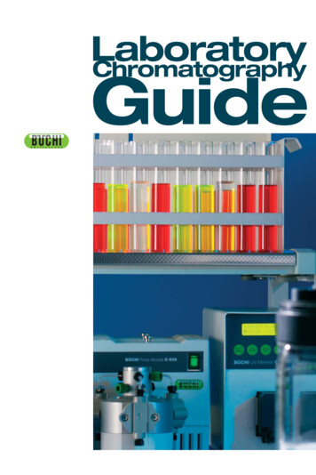
Thin-Layer Chromatography (TLC)References:Organic Laboratory Survival Manual, p. 219, 223, 249SuperOrganicLab: Then: click on “Lab Techniques,” then “Purification Procedures,” then double click on“Chromatography” and “Thin-Layer Chromatography”MIT TLC Video: MIT OpenCourseWare TLC Video for Organic LabAnalysis of Analgesics (Pain Killers) by Thin Layer ChromatographyCommon ingredients in pain killers mideNCH3PyrilamineYour task is to identify the ingredients (analgesics) in a common pain killer. You will be given knownsamples of these analgesics and you will need to compare them with the commercial samples, of whichyou will not know the composition. You will analyze the six known analgesics with the other members ofyour group.Unfortunately, commercial pain killers contain mixtures of compounds so you will not be able to usemelting point as a comparison technique. Instead you will use thin layer chromatography, a method thatallows you to visualize the number of ingredients in a mixture, and by comparison with known samples,to identify those materials. Each group will analyze their own pain killer.First, prepare your developing chambers. To simplify your lives, we will have two solvent systems madeup: 90% ethyl acetate/10% toluene; and 97% dichloromethane/3% methanol. They will be in bottles in thehood. You must experiment and see which system works better. Into one 250 mL beaker, place a piece of2
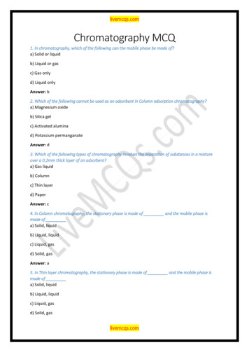
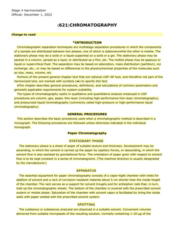
9 cm filter paper, with one edge slightly folded down as shown in Figure 1. Pour 15 mL 90% ethylacetate/10% toluene into the beaker, letting it wash over the filter paper. Cover the beaker with a watchglass. Prepare the developing chamber for the other solvent system similarly, pouring 97%dichloromethane/3% methanol into a separate 250 mL beaker with folded filter paper. Allow bothdeveloping chambers to equilibriate, covered, for 5 minutes before running a TLC plate.Figure 1. TLC Developing Chamberwith TLC Plate and Solvent Running UpFor each analgesic and for your pain killer, make a solution by weighing 100 mg (0.1 g) of compound anddissolving it, in a test tube, in 2 mL of dichloromethane (DCM). If it does not dissolve, add 2 mL ofethanol. Make separate solutions for each of the common analgesics and your pain killer.Obtain a TLC plate from the side shelf and with pencil, lightly mark a horizontal line one centimeterfrom the bottom of the plate. Do not chip away the adsorbent from the TLC plate. DO NOT WASTETHE PLATES. We have to cut them up in the stockroom. It is labor intensive and time consuming.Mark three equidistant cross-hairs along this line, one in the very center and the other two splitting thedistance from the center to the edge of the plate. Use a 2 μL disposable applicator pipet to spot thedichloromethane solution of pain killer to the plate on the center cross-hair. Try to keep the spot at 1-2mm in diameter. Use only one applicator pipet for each compound; do not cross-contaminate. Spot adichloromethane solution of analgesic on another cross-hair, left or right of the pain killer. Spot anotheranalgesic on the other side of the pain killer, so that you are running three samples per TLC plate. Labeleach spot (with pencil) corresponding to its analgesic. Look at the TLC plate under the UV lamp afteryou spot it – be sure that you see three dark circles where you spotted your samples. If not, consult yourTA. Place the plate in the 90% ethyl acetate/10% toluene developing chamber, with the sample spots onthe bottom but NOT submerged in the solvent system and such that the TLC plate does not touch the filterpaper, and cover with a watch glass. See Figure 1. Allow the solvent to wick up the TLC plate. Whenthe solvent reaches 1 cm from the top, pull the plate out and draw a line where the solvent stopped.Spot two additional TLC plates with the pain killer in the center and two different analgesics, one oneither side, and run in the 90% ethyl acetate/10% toluene developing chamber similarly. Additionally,spot three more TLC plates with the pain killer and six analgesics (three spots per plate, with the painkiller in the center for each) and run them in the 97% dichloromethane/3% methanol developing chamber.You may run multiple TLC plates in the developing chamber simultaneously as long as they (a) do nottouch the filter paper and (b) do not touch each other. Keep the watchglass on the developing chamber.Visualize your developed plates with the UV lamp on the side shelf. Trace the outline of each spot. Forexample, see the figure below. Draw each developed TLC plate in your notebook. The plates are 1 inchx 3 inches. This is a perfect size for your notebooks. The grid on the pages is 4 lines to an inch. Thismakes it easy for you to draw pictures of your TLC plates without having to trace the plates. Just use astraightedge.3
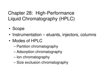
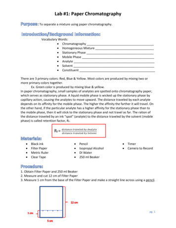
1 cmDistanceTraveledBySolventDistancesTraveledBy Compounds 1 cmOriginalSpots ofSamplesFigure 2. TLC Plate with MarkingsDetermine and record the Rf value of each component. The distance traveled by each spot is measuredfrom the origin to the center of the spot. Use a ruler with mm graduations to measure your plates.Report your Rf values to three decimal places.Rf distance compound has traveled from origindistance developing solvent has traveled from originDetermine which is your best solvent system. A good solvent system for TLC should:1) Space all of the different compounds out, so that none have the same Rf.2) Carry all compounds off of the baseline.3) NOT carry any of the compounds all the way to the top of the solvent front.If you are unsure, consult with your TA as to which is the better solvent system for your group.Using your best solvent system, compare Rf values of your pain killer spot(s) with those of the analgesicsto determine the component(s) of your pain killer.Report which analgesic compounds are contained in your commercial pain killer. Confirm yourconclusions with your TA before you leave.Waste DisposalSince we are using DCM this week, we will have special bottles in the hood labeled "HalogenatedOrganic Waste." We will always use these bottles when disposing of halogenated organics. Discard thedeveloping solvents containing DCM into a halogenated organic liquids waste bottle. The ethylacetate/toluene developing solvents should go into the nonhalogenated organic liquids waste bottle.4
Gas-Liquid Chromatography (GLC)Gas-liquid chromatography (GLC)* is an accurate and rapid process for separating and analyzingthe components of a volatile mixture. The apparatus required for this type of chromatographyconsists of the following essential parts:1. Injection block. A heated chamber for introducing and vaporizing the sample.2. Packed column. Usually a length of metal tubing packed with a porous solid that is thinly coated witha high-boiling liquid. The tube is located in an oven that can be heated at a controlled temperature.Most modern gas-liquid chromatographs use capillary columns (0.5 mm – 1.0 mm in diameter) thatare considerably longer instead of the packed columns.3. Carrier gas. The gas (usually helium or nitrogen) that carries the sample through the heated column.4. Detector. A device used to detect each component of the sample as it appears at the exit of the packedcolumn. The intensity or area of the signal indicates the quantity of the eluted component.*Gas-liquid chromatography is also called vapor-phase chromatography (VPC).The instrument works as follows: The injection block, column oven, and detector are heated to the desiredtemperature, and the inert carrier gas is passed through the apparatus. Actually, the carrier-gas stream issplit. Part of it passes through the entire apparatus, and part of it goes directly to the detector. Onecommon type of detector, called a thermal conductivity detector, consists of two heated wire filaments,one exposed only to the reference carrier-gas stream and the other exposed to the effluent gas from thecolumn.First, a small sample of the material to be analyzed is injected. The sample vaporizes in the injectionblock and is carried through the column, through the detector, and eventually out of the apparatus. As thesample is eluted from the column and passes through the detector, one of the detector wires is exposed toa mixture of carrier gas plus sample, and the other wire is exposed only to the reference stream of carriergas. The difference between the two gas streams causes a difference in the electrical conductivity of thewires, and this difference is automatically recorded. In this way a gas-liquid chromatogram is obtained.5
PROCEDURESeparation of a Two-Component MixtureInject a small sample, approximately 1 μL of the second, fifth, and last fractions from the simple andfractional distillations of the hexane-toluene mixture (Experiment 3, Distillation). Assume that the areaunder each curve is approximately proportional to the amount of material present, and calculate the ratioof the two substances in each fraction. Record the conditions used for your chromatographic separation inyour notebook.Pour any leftover hexane or toluene into the waste bottle provided.6
1 CH 2270 Chromatography (Adapted from Laboratory Manual to Accompany Organic Chemistry: A Short Course, H. Hart, L. E. Craine, D. J. Hart, and T.K. Vinod 13th ed. Brooks/Cole, Cengage Learning, Belmont, CA 2012.) Materials From the Chemicals Hood: 97% di