Transcription
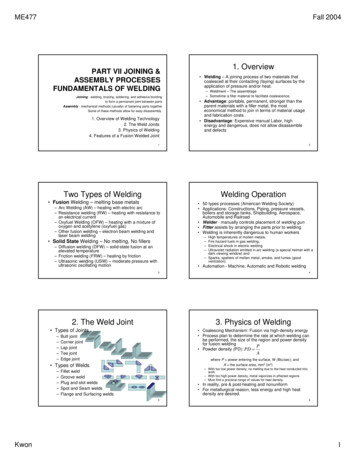
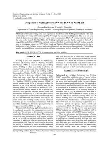
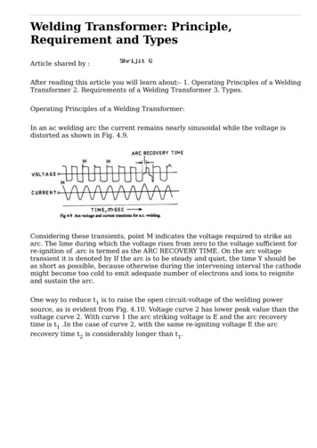
Welding Transformer: Principle,Requirement and TypesArticle shared by :After reading this article you will learn about:- 1. Operating Principles of a WeldingTransformer 2. Requirements of a Welding Transformer 3. Types.Operating Principles of a Welding Transformer:In an ac welding arc the current remains nearly sinusoidal while the voltage isdistorted as shown in Fig. 4.9.Considering these transients, point M indicates the voltage required to strike anarc. The lime during which the voltage rises from zero to the voltage sufficient forre-ignition of .arc is termed as the ARC RECOVERY TIME. On the arc voltagetransient it is denoted by If the arc is to be steady and quiet, the time Y should beas short as possible, because otherwise during the intervening interval the cathodemight become too cold to emit adequate number of electrons and ions to reigniteand sustain the arc.One way to reduce t1 is to raise the open circuit-voltage of the welding powersource, as is evident from Fig. 4.10. Voltage curve 2 has lower peak value than thevoltage curve 2. With curve 1 the arc striking voltage is E and the arc recoverytime is t1 .In the case of curve 2, with the same re-igniting voltage E the arcrecovery time t2 is considerably longer than t1.
For maintaining a sustained ac arc the welding circuit should contain aninductance* which would produce a phase difference, between the voltage andcurrent transients, of the order of 0-35 to 0-45.When welding with low currents, the cathode loses more heat than when weldingwith high currents. Therefore, in the former case the arc recovery time should beas short as possible. For example, with a current of 160 to 250 amperes an arc isreadily initiated when the transformer has an open circuit voltage of 55 to 60 voltswhile with small currents, say, 60 to 70 ampere the no load voltage of thetransformer should be 70 to 80 volts.However, an increase in the open circuit voltage may endanger the welder’s safetyand impair the power factor (i.e. Arc voltage/Open circuit voltage) of the weldingtransformer. It is therefore imperative to keep the open circuit voltage as low aspossible within the applied constraints.Requirements of a Welding Transformer:A welding transformer should satisfy the following requirements:1. It should have a drooping static volt-ampere characteristic.2. To avoid spatter, the surge of the welding current during a short- circuit shouldbe limited to the least possible above the normal arc current.3. The open circuit voltage should not normally exceed 80 volts and in no case 100volts.4. The output current should be controllable continuously over the full availablerange.5. The open circuit voltage should be just sufficiently high for ready initiation of anarc and not too high to impair the economics of welding.
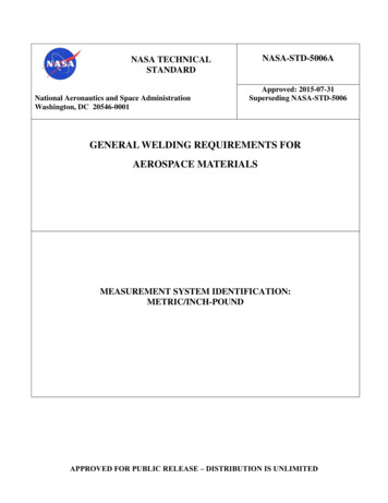
Basic Types of Welding Transformers:The four basic types of welding transformers are:1. The high reactance type,2. The external reactor type,3. The integral reactor type, and4. The saturable reactor type.1. The High Reactance Type Welding Transformer:When a transformer supplies current, magnetic fluxes are produced around itswindings.The lines of the resultant magnetic flux, ɸ, traverse the magnetic circuit and cutthe primary (I) and secondary (II) windings as shown in Fig. 4.11. However, not allthe magnetic flux lines do so. Some of the lines of magnetic flux due to primarycurrent do not cut the secondary turns and vice-versa, since both have their pathsin the air.In the diagram these partial fluxes have been marked as ɸL1 and ɸL2. In otherwords, they are responsible for the reactance* of the coils and the respectivereactive voltage drops across them. As the current increases, the leakage fluxesalso increase and so does the e.m.f. of self-induction. This is why an increase in theprimary or secondary current results in increase in the reactive voltage dropacross the respective windings.For a welding transformer to have a steeply drooping volt-ampere characteristic,both the primary and the secondary windings should have a high reactance i.e.,they should have considerable leakage fluxes. This condition is satisfied by placingthe primary and the secondary windings either on separate limbs or on the samelimb but spaced some distance apart, for example, distance ‘b’ in the above figure.
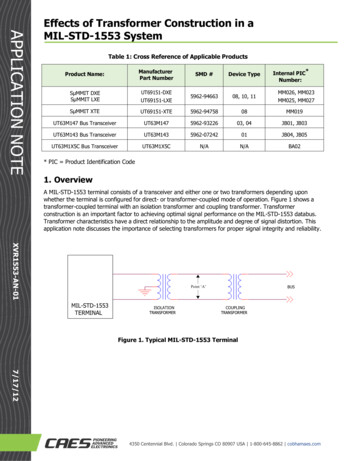
Control of current in high-reactance welding transformers can be affected by threemethods. One of them involves a moving primary coil as shown in Fig. 4.12. As thespacing between the windings is varied so does the reactance and hence theoutput welding current.
The second method is based on the use of tapped windings either on the primaryor the secondary side and the variation of the transformation ratio can be done bybringing in or out of circuit the requisite number of turns, as shown in Fig.4.13.The third method utilises movable magnetic shunt. The position of the shuntplaced in the paths of the leakage fluxes, as shown in fig. 4.14, controls the outputwelding current through control of reactance.2. External Reactor Type Welding Transformer:This type of welding transformer consists of a normal reactance, single phase, stepdown transformer and a separate reactor or choke.The inductive reactance’s and resistances of the windings in such a welding
transformer are low, so that its secondary voltage varies but a little with thewelding current. The required drooping or negative volt-ampere characteristic isensured by the reactor placed in the secondary of the welding circuit The reactorconsists of a steel core and a winding wound with a wire designed to carry themaximum allowable current.If the secondary voltage of the welding transformer is V2, the arc voltage is Varcand the total resistive cum reactive drop across the reactor is V2 then the threequantities can be diagrammatically shown as in Fig. 4.15 and are relatedmathematically as follows.Thus, the arc voltage decreases with increase in current, or with increase involtage drop across the reactor. This gives a negative or drooping volt-amperecharacteristic.Control of welding current can be achieved by two methods viz., by varying thereluctance of the reactor (the moving core reactor) or by varying the number ofturns of the winding brought in circuit (the tapped reactor).The core of the moving core reactor, as shown in Fig. 4.16, consists of a fixedportion carrying the winding, and a moving limb, which can be shifted towards oraway from the fixed core by a suitable arrangement, thus varying the air gapbetween them. An increase in air gap adds to the reluctance of the magneticcircuit of the reactor, while its self-induction and inductive reactance drop, so thatthe welding current increases.
When the air gap is reduced, the reluctance of the magnetic circuit is also reduced,the magnetic flux increases, as does the inductive reactance of the coil, and thewelding current drops. In this way the welding current can be adjusted veryaccurately and continuously.In the tapped reactor the core is made solid but the coil is divided into a number ofsections, each section having a tap brought out to the regulator point, as shown inFig. 4.17. Moving a contact arm across the taps will vary the number of turnsbrought in circuit, and with that the magnitude of welding current. Thus thecurrent is controlled in steps.3. Integral Reactor Type Welding Transformer:The welding transformer of the integral reactor type, shown in Fig. 4.18 has aprimary winding I, a secondary winding II, and a reactor winding III. Apart fromthe main limbs, the core has additional limbs carrying the reactor winding. Thecurrent is adjusted by means of moving core C placed between the additionallimbs.
The part that carries winding I and II is thus the transformer proper and the partcarrying winding III is the reactor.The reactor can be connected with the secondary either in series aiding, or inseries opposition.When the reactor is connected in series aiding, figure 4.18(a), the open circuitvoltage of the transformer will beEt E2 Erwhere E2 is the secondary voltage of the transformer and Er is the reactor voltage.Series aiding connection produces a stable arc at low currents and is employed forwelding thin plates.When reactor is connected in series opposition, as shown in Fig. 4.18(b), itsvoltage is subtracted from the open circuit voltage of the transformer, that is,Et E2 – Er
Series opposition connection is used for welding thick plates with heavy currents.4. Saturable Reactor Type Welding Transformer:In this welding transformer an isolated low voltage, low amperage dc circuit isemployed to change the effective magnetic characteristics of the magnetic core.Thus, a large amount of ac is controlled by using a relatively small amount of dc,hence making it possible to adjust the output volt-ampere characteristic curvefrom minimum to maximum. For example, when there is no dc flowing in thereactor coil, it has its minimum impedance and thus maximum output of thewelding transformer.As the magnitude of dc is increased with the help of rheostat in the dc circuit,there are more continuous magnetic lines of force thus the impedance of thereactor is increased and the output current of the welding transformer isdecreased. This method has the advantage of removing movable parts and flexingconductors and is often used for gas tungsten arc welding power supplies.Fig. 4.19 shows the basics of the circuit for a simple saturable reactor powersource. To achieve the desired aim of low voltage and high current the reactorcoils are connected in opposition to the dc control coil.With ac, the wave form for gas tungsten arc welding is quite important. Saturablereactor tends to cause severe distortion of the sine wave supplied from thetransformer. Placing an air-gap, as shown in Fig. 4.19, in the reactor core is onemethod of reducing this distortion. Alternatively, a large choke can be inserted inthe dc control circuit. Either method, or a combination of the two, will produce thedesired result.Parallel Operation of Welding Transformers:In welding operation sometimes there is a need for current exceeding themaximum welding current obtainable from one transformer. In such a case thedesired welding current can be obtained by parallel operation of two or morewelding transformers.
The precaution needed for such a parallel operation is that the no-load or opencircuit voltages of the transformers should be the same. This is particularlyessential in the case of high reactance type welding transformers where the opencircuit voltage and the transformation ratio vary to some extent according to theadjustment conditions and the control step.When two transformers are connected for parallel operation, as shown in Fig. 4.20,the like terminals of the primary windings are to be connected to the identical linewires A, B, C of the supply mains thus ensuring the coincidence of e.m.f. phases inthe secondary windings. Then the like terminals of the secondaries are to beconnected in pairs as shown. Such three phase double operator transformers aremarketed in India by M/s ES AB India Limited.Multi-Operator Welding Transformers:A multi-arc or multi-operator welding transformer system utilises a high currentconstant voltage power source for providing a number of welding circuits at thesame time. Such a system is used when there is a large concentration of weldingpoints in a relatively small operating area, for example, in ship-building,construction sites for power stations, refineries, and chemical plants.A multi-operator welding transformer with a flat volt-ampere characteristic may beof the single phase or 3-phase variety. A disadvantage of a single phase multioperator welding transformer is that it puts an unbalanced load on the 3-phasesupply mains. If a multi-operator welding transformer is to have a voltage whichwill not vary with the load (the maximum variation should not exceed 5%) it shouldhave low magnetic leakage, that is, a low inductive reactance.The number of arcs or welding circuits which can be connected to a weldingtransformer may be found by the relationship,
n It/Ia .Kwhere,n number of arcs or welding circuits,It rated output current of the welding transformer,Ia average arc current in each welding circuit,K diversity factor.The diversity factor K takes into account the fact that all the welders operatingfrom one and the same power source do not work simultaneously. The diversityfactor is related to average duty cycle and the laws of probability but is reduced asthe number of welders operating from the same transformer increases. Usually Kis assumed to be anywhere between 0 6 to 0 8.Each welding station is connected through a separate variable choke (currentregulator), which provides a steeply drooping static volt-ampere characteristiccurve for each welding circuit. The welding circuits are connected in parallel,because with this arrangement the source is better utilised when welding with lowcurrents, of the order of 70 to 100 amperes.Note:It should be noted that the welding transformers have a rather low power factordue to the fact that they incorporate coils having high inductive reactance’s.Welding transformers, therefore, must not have power ratings higher than isnecessary for the performance of the assigned job. Nor should they be run at noload for a long time.
1. The High Reactance Type Welding Transformer: When a transformer supplies current, magnetic fluxes are produced around its windings. The lines of the resultant magnetic flux, ɸ, traverse the magnetic circuit and cut the primary (I) and secondary (II) windings as shown in Fig. 4.11. However, not all the magnetic flux lines do so.