Transcription
Unison Echo Relay PanelFeedthroughInstallation ManualRevision BThis product is intended for professional use only.Read this entire document before using this product.Copyright 2015 Electronic Theatre Controls, Inc.All rights reserved. Product information and specifications subject to change.Part Number: 7123M2102 Rev: BReleased: 2015-12
ETC , Uni son Ech o , and Un ison are either regi stered trademarks or trademarks ofElectronic Th eatre Control s, I nc. i n the United States and other countries.All other trademarks, both marked an d no t ma rked, are the property of thei r respectiveowners.ETC i ntends th is do cument, whether p rinted o r electroni c, to be provi ded i n its entirety.
Table of ContentsIntroduction . . . . . . . . . . . . . . . . . . . . . . . . . 1Using this Manual. . . . . . . . . . . . . . . . . . . . . . . . . . . . . .1Warnings and Notice Conventions . . . . . . . . . . . . . . . . . 1Product Variants . . . . . . . . . . . . . . . . . . . . . . . . . . . . . . .20-10V Dimming Control . . . . . . . . . . . . . . . . . . . . . . . . . . 3DALI Control . . . . . . . . . . . . . . . . . . . . . . . . . . . . . . . . . . . 4Contact Input . . . . . . . . . . . . . . . . . . . . . . . . . . . . . . . . . . 4Ethernet Interface . . . . . . . . . . . . . . . . . . . . . . . . . . . . . . 4Ride-Thru Option . . . . . . . . . . . . . . . . . . . . . . . . . . . . . . . 4Help from ETC Technical Services . . . . . . . . . . . . . . . . .5Chapter 1Prepare for Installation . . . . . . . . . . . . . . . . 7Installation Environment . . . . . . . . . . . . . . . . . . . . . . . .7Clearance . . . . . . . . . . . . . . . . . . . . . . . . . . . . . . . . . . . . . 8Electrical Requirements . . . . . . . . . . . . . . . . . . . . . . . . . . 8Compliance . . . . . . . . . . . . . . . . . . . . . . . . . . . . . . . . . . . . 9Relay Specification . . . . . . . . . . . . . . . . . . . . . . . . . . . . . . 9Relay Ratings . . . . . . . . . . . . . . . . . . . . . . . . . . . . . . . . . 10Verify the Contents of the Shipping Carton . . . . . . . .10Parts and Specialty Tools Required . . . . . . . . . . . . . . .10Cable Specification . . . . . . . . . . . . . . . . . . . . . . . . . . . .11Cable Routing and Conduit Access . . . . . . . . . . . . . . .11Chapter 2Installation Procedure . . . . . . . . . . . . . . . . 13Install Mounting Hardware . . . . . . . . . . . . . . . . . . . . .13Mount the Relay Panel. . . . . . . . . . . . . . . . . . . . . . . . .14Connect Wiring. . . . . . . . . . . . . . . . . . . . . . . . . . . . . . .14Connect Line and Load Wiring . . . . . . . . . . . . . . . . . . . 15Connect Control Electronics Power Wiring. . . . . . . . . . 16Connect power pigtail for ERP48-FT . . . . . . . . . . . . . . . 17Install Option Cards . . . . . . . . . . . . . . . . . . . . . . . . . . .18Table of Contentsi
Option card installation location . . . . . . . . . . . . . . . . . 18Primary/Secondary switch . . . . . . . . . . . . . . . . . . . . . . . 18Connect data wiring. . . . . . . . . . . . . . . . . . . . . . . . . . . . 19DMX Control Wiring and Termination . . . . . . . . . . . . . 20Connect Emergency Contact . . . . . . . . . . . . . . . . . . . . . 20Connect EchoConnect . . . . . . . . . . . . . . . . . . . . . . . . . . 21Chapter 3Final Installation and Power Up . . . . . . . . 23Verify Installation . . . . . . . . . . . . . . . . . . . . . . . . . . . . .23Final Installation . . . . . . . . . . . . . . . . . . . . . . . . . . . . . .23Power Up and Test . . . . . . . . . . . . . . . . . . . . . . . . . . . .23iiEcho Relay Panel Feedthrough Installation Manual
IntroductionCongratulations on your purchase of the ETC Echo Relay Panel Feedthrough (ERP-FT.) Echo RelayPanels continue ETC's tradition of providing the highest quality products for the entertainment andarchitectural lighting market.Using this ManualThis manual contains procedures for field installation of the Echo Relay Panel Feedthrough, andadditional relays.When viewing this document in electronic form (pdf file) with Adobe Acrobat Reader, blue italicizedtext followed by a page number is a link within the document. If you click on the link, Acrobat willnavigate to that section or topic.Warnings and Notice ConventionsThese symbols are used in the manual and on the equipment to alert you to possible danger orimportant information.Note:Notes are helpful hints and information that is supplemental to the main text.CAUTION:A Caution statement indicates situations where there may be undefined or unwantedconsequences of an action, potential for data loss or an equipment problem.WARNING:A Warning statement indicates situations where damage may occur,people may be harmed, or there are serious or dangerousconsequences of an action.WARNING:RISK OF ELECTRIC SHOCK! This warning statement indicates situationswhere there is a risk of electric shock.Please email comments about this manual to: TechComm@etcconnect.comIntroduction1
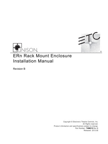
Product VariantsThis manual contains the procedures for installation of the Echo Relay Panel Feedthrough (ERP-FT).Model #ERP24-F242Model#ERP48-FT48DescriptionSmall panel with 24WR6161-811P relaysDescriptionLarge panel with48 1P relaysERP24-FT242Relay TypeRelay TypeWR6161-81VoltageDimension(inches)120V, 230V, or277V50/60Hz17.14 x 6.3 x26.24Voltage120V, 230V, or277V50/60 HzHzDimension(inches)17.14 x 6.3 x47.06ERP48-FT48Echo Relay Panel Feedthrough Installation Manual
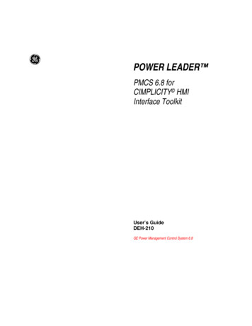
Option kits available for the Echo Relay Panel Feedthrough (ERP-FT) include:ModelDescriptionNotesERPFT-1PRKWR6161-81, 20A @ 300V AC,single pole, single space relay kitfield installed relay kitERPFT-2PRKWR6166-81, 20A @ 300V AC,double pole, single space relay kitfield installed relay kitERPFT-3PRKWR6172-84, 30A @ 480V AC,double pole, double space relay kitfield installed relay kitERPFT-RMK19” Rack Mount kitrequires 15 rack units of space forboth the 12 and 24 relay versions.Utilize two rack mount kits for the48.ERPFT-VBVoltage Barrier Kitused to separate differing voltagesand/or emergency circuits fromnormal circuits. Use per local code.Tamper Proof Hardware and ToolFor use with SmartSwitch RelayPanel, Echo Relay PanelFeedthrough, and SmartPack WallMountERPFT-TPHOption cards are available for field installation into the Sensor IQ. Each option adds another level offeatures and functions to the Sensor IQ and the installation.For more information on a specific option card, reference the appropriate installation guide suppliedwith the option card.Note:IntroductionJ4 Fluorescent 1-6J3 Fluorescent 7-12J2 Fluorescent 13-18J1 Fluore scent 19-240-10V Dimming ControlThe 0-10V Dimming Control option card (ERP-FT-LVD)provides24 outputs for control of 4-wire current-sink, 0-10VDC orelectronic loads. Each of the 24 outputs are rated to control a maximumof 400mA per channel (up to 50 ballasts per channel). Loss of power at the Sensor IQ controller results inreleasing control levels to full. The ERP-FT-LVD option card installs using an includedwire harness.A single Sensor IQ supports the use of either the 0-10V output control option or aDALI option card, but not both in the same panel.3
A BA BA BA BA BA BA BA BA BA BBBA B AB A B A B A B A BAAAA BA BA BA BA BBDALI ControlThe Digital Addressable Lighting Interface Control card(ERP-FT-DALI) controls 24 loops of 64 DALI compatibleballasts in broadcast mode. Each loop of up to 64 ballastsare linked one to one with the relay panel circuit for powercontrol.The DALI ballast must be powered by an external DALIloop power supply (supplied by others). This supply isconnected externally of the ERP. Each DALI loop requiresits own power supply and possibly more than one powersupply depending on the ballast load. Installation is limited to 64 DALI compatiblefluorescent ballasts per DALI loop. The ERP-FT-DALI Control card installs using anincluded wire harness.Contact InputThe Contact Input card (ERP-FT-CI) provides the ability todirectly control the relays using a momentary or maintaineddry contact input. The ERP-FT-CI card installs using an included wireharness.Ethernet InterfaceThe Ethernet Interface (ERP-FT-NET) provides theability to control the relay panel using the ANSI E1.11(streaming ACN) protocol and allows feedback ofcurrent and voltage information over the network. The ERP-FT-NET option card mounts to thebottom of the relay panel and connects to thetermination board using an included wireharness.Ride-Thru OptionThe Ride Thru Option (ERP-FT-RTO) maintains power tothe Sensor IQ controller for a minimum of 15 seconds inthe event of a brown-out or power loss. The ERP-FT-RTO option card mounts behind theuser interface.4Echo Relay Panel Feedthrough Installation Manual
Help from ETC Technical ServicesIf you are having difficulties, your most convenient resources are the references given in this manual.To search more widely, try the ETC Web site at www.etcconnect.com. If none of these resources issufficient, contact ETC Technical Services directly at one of the offices identified below. Emergencyservice is available from all ETC offices outside of normal business hours.When calling for help, please have the following information handy: Model of the Relay Panel Type of relays used including model number and quantity Other components in your system including station, network equipment, other panels, etc. DMX control source used for system-wide control, if any.AmericasETC InternationalTechnical Services Department3031 Pleasant View RoadMiddleton, WI 53562800-775-4382 (USA, toll-free) 1-608 831-4116service@etcconnect.comAsiaETC Asia, Ltd.Technical Services DepartmentRoom 1801, 18/FTower1, Phase 1, Enterprise Square9 Sheung Yuet RoadKowloon Bay, Kowloon, Hong Kong 852 2799 1220service@etcasia.comIntroductionUnited KingdomElectronic Theatre Controls, Ltd.Technical Services Department26-28 Victoria Industrial EstateVictoria Road,London W3 6UU, UK 44 (0)20 8896 1000service@etceurope.comGermanyElectronic Theatre Controls, GmbHTechnical Services DepartmentOhmstrasse 393607, Holzkirchen, Germany 49 (80 24) 47 00-0techserv-hoki@etcconnect.com5
6Echo Relay Panel Feedthrough Installation Manual
Chapter 1Prepare for InstallationFor proper operation of your Echo Relay Panel Feedthrough, ensure that the intendedinstallation location conforms to the following environmental and electrical requirements.Installation Environment Dry room (10-90% humidity, non-condensing), 0-40 C (32-104 F) ambient temperature, dustfree. Echo Relay Panel Feedthrough 24 is intended to be wall mounted (surface only) or installed in astandard 19” (EIA) equipment rack utilizing the 19” rack mount kit (SS-RMK). The installationlocation must support a fully populated panel not exceeding 22.68kg (50lbs). Echo Relay Panel Feedthrough 48 is intended to be wall mounted (surface only) or installed in astandard 19” (EIA) equipment rack utilizing two 19” rack mount kits. The installation locationmust support a fully populated panel not exceeding 45.36kg (100lbs).Relay Panel DimensionsModels120V 24 circ120V 48 circ277V 24 circ277V 48 circPrepare for InstallationHeight26.24” (66.64cm)47.06” (119.53cm)26.24” (66.64cm)47.06” (119.53cm)Width17.14” (43.53cm)17.14” (43.53cm)17.14” (43.53cm)17.14” (43.53cm)Depth6.3” (16cm)6.3” (16cm)6.3” (16cm)6.3” (16cm)7
Clearance ERP24-FT suggested mounting 48” (1,231mm) height to bottom of the Relay Panel. ERP48-FT suggested mounting 24” (609.6mm) height to bottom of the Relay Panel. Clearance on left and right side of the panel should be 1.5” (38.46mm). Zero clearance requiredif mounted next to another relay or dimming rack. Suggested door clearance is 12” (304.8mm)from front of the panelDoorClearance 609.6 mm)48”(1,23 1mm)FloorElectrical Requirements 8A dedicated circuit from the breaker panel for control electronics power.120V, 50/60 Hz or 277VERP24-FT requires 8A maximum current per Relay PanelERP48-FT requires 15A maximum current per Relay PanelThis equipment must be connected to a suitable safety earth/ground.Echo Relay Panel Feedthrough Installation Manual
ComplianceUL ListedUL508 file #E92154, UL924 file #E242514FCCThis device complies with part 15 of the FCC Rules. Operation is subject to the following twoconditions: (1) This device may not cause harmful interference, and (2) this device must acceptany interference received, including interference that may cause undesired operation.Relay SpecificationEcho Relay Panel Feedthrough (ERP-FT) ships standard with either 24, or 48 - 20A HID relaysinstalled and fully pre-wired for low voltage control. Three relay types are available asstandard: 20A single pole/single space relay (WR6161K-84) 20A double pole/single space relay (WR6166-84) 20A double pole/double space relay (WR6172-84)As required, custom ERP-FT Panels are available including a variable number of relays. Forcustomer convenience a field-install relay kit is available and includes a relay and the lowvoltage control leads.12121242-8617 LAYWRPOLE RE2-6-81616 LAYWR OLE RE2-P11-8616 LAYWRPOLE RE1-ERPFT-1PRK - single pole, single space 20AHID relay kitERPFT-2PRK - double pole, single space 20AHID relay kitERPFT-480V - double pole, double space 20AHID relay kitWR6161K-84 Single Pole HID RelayCSAUL Listed General Use20A @ 347VAC Ballast (Standard)20A @ 347VAC Tungsten2400W @ 120VAC1/2 HP @ 110-125VAC1-1/2 HP @ 220-250VAC18,000A 277VAC Motor Load Short Circuit Rating General Use Ballast (Standard) Ballast (Electronic) Tungsten20A @ 300VAC20A @ 300VAC20A @ 277VAC2400W @ 120V AC1/2 HP @ 110-125V AC Motor Load1-1/2 HP @ 220-277V AC Short Circuit Raiting 18,000A 277VACWR6166-84 Double Pole HID RelayCSA General Use Ballast (Standard) Tungsten Motor Load20A @ 347VAC20A @ 347VAC2400W @ 120VAC1/2 HP @ 110-125VAC1-1/2 HP @ 220-250VAC Short Circuit Rating 5,000A 277VACPrepare for InstallationUL Listed General Use Ballast (Standard) Tungsten Motor Load20A @ 300VAC20A @ 300VAC2400W @ 120VAC1/2 HP @ 110-125VAC1-1/2 HP @ 220-277VAC Short Circuit Rating 5,000A 277VAC9
WR6172-84 Double Pole 480V HID RelayCSA General Use Ballast (Standard) Tungsten Motor Load20A @ 347VAC20A @ 347V AC2400W @ 120V AC1/2 HP @ 110-125V AC1-1/2 HP @ 220-250V AC Short Circuit Rating 5,000A 277VACUL Listed General Use Ballast (Standard) Tungsten Motor Load Short Circuit Rating20A @ 480VAC20A @ 480VAC2400W @ 120V AC1/2 HP @ 110-125V AC1-1/2 HP @ 220-277V AC5,000A 277VACRelay Ratings Inrush: 2000AIsolation: 5000V RMSLife: 60,000 cycles at full loadRelay output terminals accept 1.5 - 4mm2 (14-10 AWG) copper wireVerify the Contents of the Shipping CartonStandard ERP-FT units ship complete and fully pre-wired with low-voltage relay control. Asyou remove the Relay Panel from the shipping carton, confirm the following items areincluded: ERP-FT with cover(s) and locking door(s) attached with key(s).Relay panel interior(s) with the quantity and type of relay orderedDMX Preparation Kit - ETC part number 4100A1002Echo Relay Panel Feedthrough Installation ManualNote:Accessory options are packaged separately.Parts and Specialty Tools RequiredThe following parts and specialty tools are required, but not supplied, for installation: 6-8mm (1/4” - 3/8”) bolts or screws, 50-100mm (2-4”) long, and suitable wall plugs, aresuggested for Relay Panel mounting. Conduit punch, Conduit or bushes - 12.7mm (1/2”) diameter Phillips screwdriver Slotted screwdriver Jeweler’s slotted screwdriver Wire strippers10Echo Relay Panel Feedthrough Installation Manual
Cable SpecificationPurposePower ControlProcessor ElectronicsCable Type / DescriptionNoteA dedicated circuit is recommended. 8A for theERP24-FT and 15A for the ERP48-FT.For installations utilizing UL 924 for emergencylighting loads, secure a dedicated emergencycircuit.120V, 230V, or 277V AC50/60HzLine / Load4mm2 (10 AWG) maximumcoppermaximum 20A @ 300V AC per relayDMXBelden 9729 (recommended)or equivalent - for use with an external DMXcontrol source (not included). DMX is RS485serial and follows a daisy-chained topology.Echo Control Stationsand SensorsEmergency UL 924Belden 8471 plus 1 - 2.5mm2For use with wall stations and Echo enabled panel(14 AWG) ESD drain wireto panel communications. Echo is FTT-10Arecommended (drain wire notrequired if installed in grounded topology-free and polarity independent.metal conduit)Contact input for UL 924 emergency lighting2 - 1.5mm2 (16 AWG), twisted loadsCable Routing and Conduit AccessEcho Relay Panel Feedthrough has removable plates located on top, bottom and both sides toaccommodate conduit fittings for line, load and feed wiring. Two knockouts, one on eachside of the user interface, are specifically provided for low voltage (control) wiring.Removable plates on top, bottom, or sidesRemove plate to punch conduit access as needed for line, load, and control electronic power wiring.It is acceptable to remove the plate permanently if the unit is mounted directly next to an adjacentFeed Through Echo Relay Panel.Power Control Processor120, 50/60Hz2 wire and sin the lower sidepanelsaccommodate12.7mm (1/2”)conduit orbushes for lowvoltage controlPrepare for InstallationI/O compartmentLow voltage (Class 2)termination pointlocated behind theuser interface.11
12Echo Relay Panel Feedthrough Installation Manual
Chapter 2Installation ProcedureInstall Mounting HardwareStep 1:Remove the front cover(s) with locking doors to reveal the relay panel interior.Step 2:Hold the Relay Panel to the desired mounting location.Step 3:Mark the keyhole locations on the wall with a pencil. ERP-FT 24 panels can install up to two-high by any width. ERP-FT 48 panels are 44cm (17.35”) wide by 120.1cm (47.3”) high, includingremovable panels and screws.Allow clearances as described on page mm)15.5”(394mm)Step 4:Once all marks have been made, set the Relay Panel aside.Step 5:Install the required hardware for mounting the enclosure using the previously markedreference points as a guide. ERP24-FT requires four 6-8mm (1/4” - 3/8”) bolts or screws,50-100mm (2-4”) long and suitable wall plugs.- Both the surface and mounting hardware must support 22.68kg (50lbs).- Expose at least 25mm (1”) of threads for mounting the Relay Panel.Installation Procedure13
ERP48-FT requires six 6-8mm (1/4” - 3/8”) bolts or screws, 50-100mm (2-4”) longand suitable wall plugs.- Both the surface and mounting hardware must support 45.36kg(100lbs).- Expose at least 25mm (1”) of threads for mounting the Relay Panel.Mount the Relay PanelStep 1:Mount the ERP-FT enclosure to the installed mounting bolts.Step 2:Tighten the bolts securely.a: Check for a plumb installation and follow all local code restrictions.Step 3:Rough-In Conduit and CableThe Echo Relay Panel Feedthrough has removable plates located on top, bottom and bothsides to accommodate conduit fittings for line, load and control electronics power wiring.Remove the plates to punch conduit access as required.Step 1:Note:Step 2:Note:Install conduit for line, load and control electronics power to the panels in theappropriate locations. See Cable Routing and Conduit Access on page 11. The Echo Relay Panel Feedthrough is available as standard with 12, 24, 36, or 48relays installed. Size conduit appropriately for the specified wire and loads.It is the installing contractor’s responsibility to comply with all local electrical codes.For UL 924 emergency installation, secure an emergency power source for controlelectronic power and line feeds as required.Install conduit as required for low voltage control wiring.All low voltage (control) wiring must be routed separately from high voltage wiring. All low voltage terminations are conveniently located behind the User Interface ofthe panel. Two 12.7mm (1/2”) knockouts are provided for low voltage controlwiring.Step 3:Pull line, load, and control electronics power wiring through conduit.a: Individual line feeds from branch circuit breaker to relays.b: Individual load wires from the relays to the lighting loads.c: A dedicated circuit for control electronics power.Step 4:Pull low voltage (control) wiring through the conduit to the I/O compartment knockouts.See Cable Routing and Conduit Access on page 11.Connect WiringRelays - Each relay has staggered output contacts for easy access to line and load connection.A Phillips screwdriver and wire strippers are required for relay line and load terminations.Control Electronics Power - A discrete circuit (8A current maximum per ERP24-FT and 15Amaximum current for ERP48-FT) is required to power the Power Control Processor.Terminations require only a flat head jeweler screwdriver and wire strippers.I/O terminations - Easy access to all low voltage control terminations. The User Interfacepanel folds down to reveal connection points for DMX, Network, Contact Input, 0-10VControl, and DALI control.14Echo Relay Panel Feedthrough Installation Manual
Connect Line and Load WiringERP-FT is shipped standard with either 24 or 48 relays installed. Depending on customerrequirements the relay type and quantities may vary for custom orders. Three relay types areavailable for customer convenience, 20A single pole relay (Aromat WR6161-81), a 20Adouble pole relay (Aromat WR6166-81) and a 30A 480V double pole relay (WR6172-84).WARNING:RISK OF DEATH BY ELECTRIC SHOCK! Failure to disconnect all powerto the panel before working inside the panel could result in seriousinjury or death.De-energize main feed to relay panel and follow appropriate Lockout/Tagout procedures as described in NFPA Standard 70E. It is importantto note that electrical equipment such as relay panels, can present anarc flash safety hazard if improperly serviced. This is due to availablelarge short circuit currents on the feeders of the equipment. Anywork on energized equipment must comply with OSHA Electrical SafeWorking Practices.Wiring RacewayeLindLoaLine / Loadterminations forrelays 1, 3, 5.23AC Input120V or 277V,50/60HzLine / Loadterminations forrelays 2, 4, 6. 24.AC Input120V or277V 50/60HzControlterminationsLine / Loadterminations forrelays 25, 27,29.47Step 1:Installation ProcedureLine / Loadterminations forrelays 26, 28,30.48Connect “Line” from the circuit breaker to the designated relay.15
Note:Reference the circuit panel schedule for accurate terminations from circuit breakerpanel to Relay Panel then to lighting loads. The circuit panel schedule should bemaintained and stored on the inside door of the Relay Panel.a: Strip 6mm (1/4”) of insulation from the end of the copper wire.b: Insert the bare-end into the relay output screw terminal and secure.Step 2:Connect “Load” to the designated relay.a: Strip 6mm (1/4”) of insulation from the end of the copper wire.b: Insert the bare-end into the remaining relay output screw terminal and secure.Note:A Voltage Barrier may be used to separate multiple voltages and/oremergency circuits from normal circuits within the Relay Panel. This isan accessory option, sold separately, and available for use when localcode requires. Contact ETC for assistance.Step 3:Repeat this process for the remaining Line and Load wires for the installation.CAUTION:Dress the wire bundles neatly and remove all cuttings and dirt before proceedingwith the installation. Debris left in the panel may short the electronics at power upand void the factory warranty.Connect Control Electronics Power WiringWARNING:RISK OF ELECTRIC SHOCK! Check power is OFF at the circuit breakerprior to proceeding with control electronics power wiring.Control electronics input power connects in the ERP-FT on screw terminals. The transformeris rated for 120V AC at 50/60Hz.Step 1:Connect line, Neutral and ground wiring on the designated screw terminals. Use thediagram below to determine where each wire lands depending on voltage.Step 2:Tighten the screws firmly onto each wire.120V AC operationControl Elec.Power277 V120 VNeutralNote:16When installing the ERP48-FT Relay Panel, input power connects to the transformerin the top panel as indicated above. Standard ERP48-FT ships from the factory witha power pigtail connected between the two transformers in the panel. To confirm anaccurate installation, reference Connect power pigtail for ERP48-FT on page 17.Echo Relay Panel Feedthrough Installation Manual
Connect power pigtail for ERP48-FTA spiral wrapped cable is hard wired to the transformer in the top panel of the and ERP48-FTand connects to the transformer in the lower panel. This connection is made at the factoryprior to shipment of standard 48 Relay Panels.When non-standard ERP48-FT units are shipped from the factory this connection must becompleted by the installing contractor. The power pigtail is hard wired to the transformer inthe top panel. Reference the graphic below for indication of cable routing and connection ofthe free end of the power pigtail.Front View - covers removedRight Side - cutoutAC Input120V, 230V or 277VAC 50/60HzFeed the free endof the powerpigtail through theplenum area.Pull the powerpigtail throughthe plenum areato the lowertransformer.Connect theMate-N-Lok connector to thereceptacle.Installation Procedure17
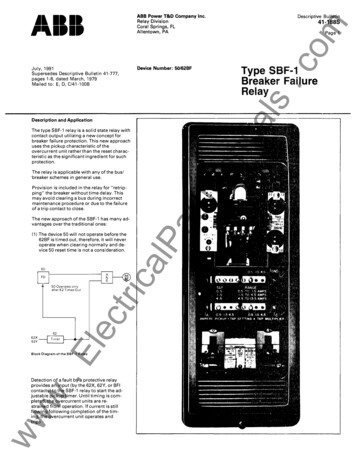
Install Option CardsEach option card is packaged separately and comes with its own installationinstructions.Option card installation locationNetworkOption CardDALI Option Card or0-10V Option CardContact InputOption CardRide ThruOptionPrimary/Secondary switchWhen using two of either the 0-10V or DALI controloption cards in an ERP48-FT you will need to positionthe primary secondary prior to startup. The primarysecondary switch controls which set of relays respondsto which option card. When using two different option cards, move theswitch to position 1. When using two of the same option cards, movethe switch to position 2.pos. 1pos. 2Primary/SecondaryswitchWith the switch in position one, each card will controlthe circuits assigned to it, up to 24 circuits.With the switch in position two, the card connected tothe “option 1” connector will control circuits 1-24.The card connected to “option 2” connector willcontrol circuits 25-48.Option Card 1Option Card 20-10V (outputs 1-24DALI (outputs 1-240-10V (outputs 1-24)DALI (outputs 1-24)0-10V (outputs 25-48)DALI (outputs 25-48)Contact InputContact Input18Optioncard 1Optioncard 2Primary/Secondary SwitchPositionSecondarySecondaryPrimaryPrimaryEcho Relay Panel Feedthrough Installation Manual
Connect data wiringData and Control Wire SpecificationPurposeRecommended CableNotesDMX In andDMX Pass-Thru(J8 and J9)Belden 9729or equivalent (contact ETC for list ofequivalents). DMX is RS485 serial and canbe installed in series (i.e. daisy-chain)topology.ERP-FT-NET (J4)Belden 1583A (Category 5e or better)Install per EIA/TIA 568B. Test to TSB 67standards.2 - 1.5mm2 (16 AWG), twisted pairContact input for UL 924 emergencylighting loads.EchoConnect stationbus (J6)Belden 8471 (or equivalent) plus one14 AWG (2.5mm2) ESD ground wireTopology-free. The total length of allsignal wiring cannot exceed 1,640 feet(500m).0-10V DimmingControl (J5)12-24 AWG (4-.25mm2) Class 1 wiremaximum of 50 ballasts (400mA) perchannelDALI (J5)12-24 AWG (4-.25mm2) Class 1 wiremaximum of 64 ballasts per loopEmergency In and OutUL 924 emergencyContact Input(J2 and oncard #1GroundwireEcho stationNetwork controlPanicinOptioncard #2DMXthruPanicoutDMXInDMXterminationLow voltage boardconnectorsInstallation Procedure19
DMX Control Wiring and TerminationDMX wire preparation will vary with the type of wire and termination kit being utilized. Pleaserefer to the instructions provided with the DMX termination kit for specifics on the wirepreparation. DMX termination is made to J8 and J9 on the termination board.If daisy-chaining toanother rack orDMX device.COMData (Red)The graphic on the left illustrates DMX termination using screwterminal connectors that are intended for use with Belden 9729cable (or approved equal).Screw terminal connectors are supplied in the DMX PreparationKit w/ Screw Connector, part number 4100A1012, and shippedwith your Echo Relay Panel.n/cn/cn/cn/cn/cData - (Black)From DMXsourceData - ORGCom W/BRNData W/ORGBRNGRNW/GRNBLUThe graphic on the right illustrates DMX termination using IDCconnectors that are intended for use with Category 5 solid corecable (or equivalent cable types). IDC connectors are supplied inthe Cat5 Preparation Kit w/ IDC Connector, part number4100A1013, and shipped only when ordered separately.W/BLUBe aware that cable other than Belden 9729 may have a differentcolor code for its wire pairs.Use a second connector on the DMX Pass-Thru if daisy-chaining toanother panel or DMX device.ONOFFRDMAfter completing the DMX data connections, you must properly terminate the DMX line usingthe termination switch (S1) on the relay panel termination board. Data termination eliminatesreflections at the end of the DMX data run.Turn on DMX terminationin the last panel/device thatis physically connected inthe DMX chain.Connect Emergency ContactThe Echo Relay Panel Feedthrough can connect to an externalemergency circuit. Emergency can be triggered by a normallyopen or normally closed contact input. In addition, the relay paneloptionally offers a 24Vdc (maximum 25mA) Emergency Out thatprovides a feed to a lamp or LED, indicating emergency activity.20Echo Relay Panel Feedthrough Installation Manual
Connect Emergency InputStep 1:Pull two 16 AWG (1.5mm2) wires from your Emergency contact location to the EchoRelay Panel through conduit. See Cable Routing and Conduit Access on page 14.Step 2:Strip 3/16” (5mm) of insulation from the ends of each wire.Step 3:Remove the two pin Emergency Input connector from J2 on the termination I/O board.Step 4:Loosen t
architectural lighting market. Using this Manual This manual contains procedures for field installation of the Echo Relay Panel Feedthrough, and additional relays. When viewing this document in electronic form (pdf file) with Adobe Acrobat Reader, blue italicized text