Transcription
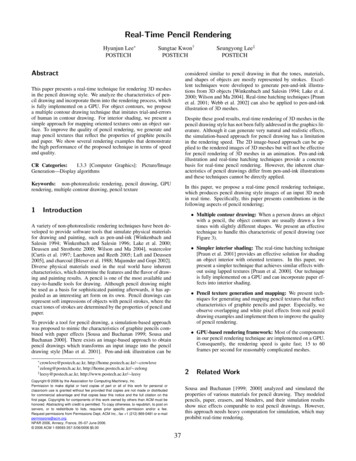
Real-Time Pencil RenderingHyunjun Lee POSTECHSungtae Kwon†POSTECHAbstractconsidered similar to pencil drawing in that the tones, materials,and shapes of objects are mostly represented by strokes. Excellent techniques were developed to generate pen-and-ink illustrations from 3D objects [Winkenbach and Salesin 1994; Lake et al.2000; Wilson and Ma 2004]. Real-time hatching techniques [Praunet al. 2001; Webb et al. 2002] can also be applied to pen-and-inkillustration of 3D meshes.This paper presents a real-time technique for rendering 3D meshesin the pencil drawing style. We analyze the characteristics of pencil drawing and incorporate them into the rendering process, whichis fully implemented on a GPU. For object contours, we proposea multiple contour drawing technique that imitates trial-and-errorsof human in contour drawing. For interior shading, we present asimple approach for mapping oriented textures onto an object surface. To improve the quality of pencil rendering, we generate andmap pencil textures that reflect the properties of graphite pencilsand paper. We show several rendering examples that demonstratethe high performance of the proposed technique in terms of speedand quality.Despite these good results, real-time rendering of 3D meshes in thepencil drawing style has not been fully addressed in the graphics literature. Although it can generate very natural and realistic effects,the simulation-based approach for pencil drawing has a limitationin the rendering speed. The 2D image-based approach can be applied to the rendered images of 3D meshes but will not be effectivefor pencil rendering of 3D meshes in an animation. Pen-and-inkillustration and real-time hatching techniques provide a concretebasis for real-time pencil rendering. However, the inherent characteristics of pencil drawings differ from pen-and-ink illustrationsand these techniques cannot be directly applied.CR Categories:I.3.3 [Computer Graphics]: Picture/ImageGeneration—Display algorithmsKeywords: non-photorealistic rendering, pencil drawing, GPUrendering, multiple contour drawing, pencil texture1Seungyong Lee‡POSTECHIn this paper, we propose a real-time pencil rendering technique,which produces pencil drawing style images of an input 3D meshin real time. Specifically, this paper presents contributions in thefollowing aspects of pencil rendering;Introduction Multiple contour drawing: When a person draws an objectwith a pencil, the object contours are usually drawn a fewtimes with slightly different shapes. We present an effectivetechnique to handle this characteristic of pencil drawing (seeFigure 3).A variety of non-photorealistic rendering techniques have been developed to provide software tools that simulate physical materialsfor drawing and painting, such as pen-and-ink [Winkenbach andSalesin 1994; Winkenbach and Salesin 1996; Lake et al. 2000;Deussen and Strothotte 2000; Wilson and Ma 2004], watercolor[Curtis et al. 1997; Laerhoven and Reeth 2005; Luft and Deussen2005], and charcoal [Bleser et al. 1988; Majumder and Gopi 2002].Diverse physical materials used in the real world have inherentcharacteristics, which determine the features and the flavor of drawing and painting results. A pencil is one of the most available andeasy-to-handle tools for drawing. Although pencil drawing mightbe used as a basis for sophisticated painting afterwards, it has appealed as an interesting art form on its own. Pencil drawings canrepresent soft impressions of objects with pencil strokes, where theexact tones of strokes are determined by the properties of pencil andpaper. Simpler interior shading: The real-time hatching technique[Praun et al. 2001] provides an effective solution for shadingan object interior with oriented textures. In this paper, wepresent a simpler technique that achieves similar effects without using lapped textures [Praun et al. 2000]. Our techniqueis fully implemented on a GPU and can incorporate paper effects into interior shading. Pencil texture generation and mapping: We present techniques for generating and mapping pencil textures that reflectcharacteristics of graphite pencils and paper. Especially, weobserve overlapping and white pixel effects from real pencildrawing examples and implement them to improve the qualityof pencil rendering.To provide a tool for pencil drawing, a simulation-based approachwas proposed to mimic the characteristics of graphite pencils combined with paper effects [Sousa and Buchanan 1999; Sousa andBuchanan 2000]. There exists an image-based approach to obtainpencil drawings which transforms an input image into the pencildrawing style [Mao et al. 2001]. Pen-and-ink illustration can be GPU-based rendering framework: Most of the componentsin our pencil rendering technique are implemented on a GPU.Consequently, the rendering speed is quite fast; 15 to 60frames per second for reasonably complicated meshes. crowlove@postech.ac.kr,http://home.postech.ac.kr/ crowlovehttp://home.postech.ac.kr/ zelong‡ leesy@postech.ac.kr, http://www.postech.ac.kr/ leesy† zelong@postech.ac.kr,2Copyright 2006 by the Association for Computing Machinery, Inc.Permission to make digital or hard copies of part or all of this work for personal orclassroom use is granted without fee provided that copies are not made or distributedfor commercial advantage and that copies bear this notice and the full citation on thefirst page. Copyrights for components of this work owned by others than ACM must behonored. Abstracting with credit is permitted. To copy otherwise, to republish, to post onservers, or to redistribute to lists, requires prior specific permission and/or a fee.Request permissions from Permissions Dept, ACM Inc., fax 1 (212) 869-0481 or e-mailpermissions@acm.org.NPAR 2006, Annecy, France, 05–07 June 2006. 2006 ACM 1-59593-357-3/06/0006 5.00Related WorkSousa and Buchanan [1999; 2000] analyzed and simulated theproperties of various materials for pencil drawing. They modeledpencils, paper, erasers, and blenders, and their simulation resultsshow nice effects comparable to real pencil drawings. However,this approach needs heavy computation for simulation, which mayprohibit real-time rendering.37
Contour DrawingDrawingContourMao et al. [2001] proposed an image transformation technique thatchanges an input image to have the pencil drawing style. They construct a 2D vector field on an image and apply the line integral convolution to the vector field to generate pencil strokes. In this paper,we consider 3D meshes as the input for pencil rendering, instead of2D images.Interior ShadingShadingInteriorWinkenbach and Salesin [1994] developed a rendering techniquethat generates pen-and-ink illustrations from 3D meshes andshowed impressive results. Lake et al. [2000] presented realtime rendering techniques in various styles, including pencil sketchshading, with projected textures. Saito and Takahashi [1990] introduced line drawing on an object surface based on a curvature fieldfor comprehensible rendering of 3D shapes. Salisbury et al. [1997]compute a direction field on a 2D image and map orientable textures to produce pen-and-ink illustrations. However, in these techniques, the inherent characteristics of pencil drawing are not reallyinvestigated.Run-timeRun-time ProcessProcessContourContour al/DepthMapMap RenderingRenderingDistortedDistorted PlanePlaneGenerationGenerationPencilPencil LineLine nhancementTextureTexture lation3-Way3-Way BlendingBlendingPaperPaper NormalNormalTextureTexture GenerationGenerationPaperPaper EffectEffectFigure 1: System overviewWith the advances of graphics hardware, real-time techniques fornon-photorealistic rendering have been developed. Praun et al.[2001] presented a real-time hatching technique, which can mapstroke textures onto a 3D mesh surface with level-of-detail control.Webb et al. [2002] extended this technique with volume rendering hardware and pixel shaders to enhance the control of hatchingtones. Majumder and Gopi [2002] introduced a real-time techniquefor charcoal rendering of 3D objects, which utilizes graphics hardware. In this paper, we present a real-time rendering technique forpencil drawing of 3D meshes, which can handle texture mappingof orientable strokes with a simpler approach than previous work.With the simplicity, our technique is readily implemented by GPUprogramming.pixel brightness, similar to charcoal rendering [Majumder and Gopi2002]. To express pencil strokes, we use texture rotation and 3way blending for mapping oriented pencil textures in the principalcurvature directions. To represent interaction among a pencil andpaper, we model paper as a height field and the paper normals areused to control the pixel intensities during the mapping of orientedpencil textures. In interior shading, all steps are performed in asingle pixel shader, except that a simple vertex shader is used toproject the 3D principal curvature directions at vertices onto the 2Dimage space.For stylization of 3D object contours, Mohr and Gleicher [2001]used jittering to mimic the multiple contours in a pencil drawing.Loviscach [2004] demonstrated that multiple contour drawing canbe supported by graphics hardware. However, in this paper, wepresent a more efficient technique for multiple contour drawing,which is implemented by a pixel shader with multi-texturing. Sinceour technique simply distorts the underlying plane of the contoursto produce different trajectories, it can handle arbitrarily complexcontours very efficiently.3PreprocessingPreprocessingAfter contour drawing and interior shading, the resulting imagesare composed and enhanced to produce the final image. This stepis fully performed in a pixel shader using the images from contourdrawing and interior shading as texture images mapped onto thewhole screen.In the preprocessing step, we prepare several data that will be usedin the run-time process. This step needs to be performed only oncefor each input model, thus the computation speed is not really important. For contour drawing, we generate a texture to be used forgiving pencil tones to the contours. This texture can be simplerthan the pencil texture used for interior shading because contoursoccupy small narrow parts of the rendered image without revealingthe texture details. We also construct distorted planes to be used formodifying contour trajectories. For interior shading, we generate aset of pencil textures to represent different intensities of an objectinterior. The principal curvature directions are computed for meshvertices to determine the orientations in interior texture mapping. Apaper model is constructed as a height field and the normal vectorat each pixel is computed to provide paper effects in interior texturemapping.System OverviewIn a drawing, objects are usually depicted by contours and interiorshading. In our system for pencil rendering of a 3D mesh, the runtime process consists of contour drawing and interior shading partswhose output images are combined to generate the final image (seeFigure 1).In contour drawing, we first render the input mesh to obtain normaland depth images from the shape. The normal and depth images arethen used to detect contours in image space. To make the extractedcontours look natural, similar to pencil drawing by a human, wedraw the contours a few times with slightly distorted trajectories.The pencil tones of the contours are represented by mapping a pencil texture. The normal and depth images are obtained by OpenGLrendering of a mesh, and the succeeding image-based contour detection is performed by a pixel shader. After contours have beenobtained, another pixel shader handles multiple contour drawingand pencil texture mapping at the same time.Once all necessary data have been prepared in preprocessing, therun-time process for pencil rendering of a 3D mesh is fully supported by graphics hardware and performed very fast with varyingcamera and lighting parameters. In contour drawing, we mimic thetrial-and-error of human by multiple contour drawing with distortedtrajectories. In interior shading, pencil textures and paper effectsthat reflect characteristics of graphite pencils provide natural impressions with an object interior. The details of the techniques aredescribed in the following sections.The interior shading part starts with intensity computation for theinput mesh to determine the brightness of pixels in the renderedimage. To introduce pencil drawing tones, we adjust the contrast of38
44.1Contour DrawingFigure 2(a) shows an example of the distorted plane with perturbedrectangles. Figure 2(b) shows shaken contours obtained by texturing a contour image onto a distorted plane.Contour detectionMany algorithms exist for detecting contours from a 3D mesh.Among them, we use an image space approach, which can detectcontours in real time using GPU and enables us to apply imageprocessing techniques to detected contours [Isenberg et al. 2003;Nienhaus and Doellner 2003]. This approach detects contours using normal and depth images acquired from a 3D object. Suggestive contours [DeCarlo et al. 2003] can also be extracted in the 2Dimage space.(a) distorted planeThe result of contour detection with an image space approach isrepresented by a black and white or gray scale image. To introducelighting effects onto the contours, we modify the pixel values onthe contours using the normal information at the pixels;Ic0 lc Ic ,Figure 2: Contour shaking(1)4.3where Ic and Ic0 denote the original and modified pixel values of contours, respectively. lc is the light effect factor, which is computedwith normal and light directions at each pixel. As a result, the information for detected contours is stored as a gray scale image. Wenormalize the gray scale values between 0 and 1, where 0 is black(the darkest) and 1 is white (the brightest). Both contour detectionand lighting effects on the contours are performed on image pixelsand are easily implemented with a pixel shader.4.2When combining multiple texture values in the pixel shader, weput a darker intensity to a pixel with much overlapping of contours.This strategy imitates a darkening effect induced by overlappingpencil strokes. In addition, we project a contour pencil texture,created in the preprocessing step, onto the contours. This texturemapping introduces impression of a pencil material to the contoursand can be performed in the same pixel shader.Contours acquired by the method in Section 4.1 are artificial andmay differ from those drawn by hand. Adding errors to contourscan help to imitate hand drawing [Loviscach 2002; Ho and Komiya2004]. Although a person cannot draw contours without errors,these errors are usually bounded in some limited range. Whenthe drawing error increases, a person will try to stick to the target contour, reducing the error. This implies that shaking patternsof contour drawing can be approximated by the shape of a periodicfunction.Figure 3 shows an example of multiple contour drawing. The figures on the left are contour images created from different sine functions. The right figure is the merging result of the left images. Fromthe zoom-in image on the right, we can see that overlapping contours and pencil materials are successfully implemented.With this idea, we use a sine function to imitate the shaking errorsin contour drawing; a sin(bx c) r,Multiple contour drawingIn real pencil drawing, we can observe that a contour is usuallycomposed of overlapped multiple lines, not a single one. In ourcontour drawing, we can easily achieve this effect by composingseveral distorted contour images. With multi-texturing, we can assign several texture coordinates computed by different sine functions to the rectangles on the screen space. Then, several contoursdistorted in different ways are obtained by sampling multiple texture values at the same time in a pixel shader. From experiments,we have discovered that the number of overlapping works best at3-5.Contour shakingy(b) shaken contours(2)where a and b determine the range and period of the error, respectively. c is a shift of a periodic function and r adds randomness tothe error value.We can perturb contours by adding the errors computed with Eq. (2)directly to the contour points. However, this perturbation processwill be difficult to implement by a pixel shader because a pixelshader cannot write a value to another pixel except to the currentone. We resolve this problem by texturing the contour image ontoa distorted plane, instead of shaking contours directly.Figure 3: Multiple contour textures and the merged imageIn the preprocessing step, we divide the screen space into regularlysized rectangles. We assign the coordinates on the contour image tothe texture coordinates of the rectangles so that the contour imagemay be redrawn by texturing the rectangles with the contour image.Then, distorted contours can be obtained by adding errors to thetexture coordinates of the rectangles and performing texture mapping afterwards. The distorted texture coordinates for the rectanglesare computed with Eq. (2) in the preprocessing step and repeatedlyused in the run-time rendering process.5Interior ShadingIn pencil drawing, various effects are considered for the interiorof an object, such as the color and material of a pencil, the directions and thickness of strokes, the paper material, and the blending39
and eraser effects [Sousa and Buchanan 1999]. In the preprocessing step, we create pencil textures that reflect the color and material of a pencil represented with oriented strokes. We also makea paper texture that mimics the material of paper. In the run-timeprocess, pencil textures are rotated with the principal curvature directions and blended by multi-texturing, representing the directionsand brightness of strokes on the object interior. The paper textureis used to implement the interaction of a pencil with paper in interior stroke mapping. The run-time process for interior shading isimplemented in a single pixel shader.5.1even though strokes are added on the paper many times afterwards.To achieve this property, we add a conditional formula at the end ofEq. (3);If ct is white enough, ca µw ca .(4)With a small value of µw , we can preserve white pixels. Empirically, a value between 0.3 and 0.5 is good for µw .We use a 3D texture space to store various tones of pencil textures [Webb et al. 2002]. Since no stroke is needed for the brightestregion, a white image is stored as the brightest texture. Includingthe white image, 32 pencil textures are stored in the 3D texturespace. We make the colors of these textures uniformly distributedfrom the brightest to the darkest when the textures are generated byoverlapping strokes.Pencil texture generationPencil textures for interior shading should express essential properties of pencil strokes, such as brightness and thickness. In addition,strokes in textures should have a specific direction to depict the voluminousness of an object along the direction. To obtain such penciltextures, we propose a texture generation technique based on [Webbet al. 2002] and use a pixel shader to implement the technique.5.2Brightness adjustmentThe object surface brightness for pencil rendering can be computedby a general shading technique, e.g., Gouraud shading. Such computed brightness may not be sufficient for expressing a voluminousobject. Majumder and Gopi [2002] enforce the voluminousness byenhancing the contrast of colors, where a brightness value is replaced by its square.In [Webb et al. 2002], the brightness of an object part is representedby the density of strokes. On the other hand, a pencil drawing expresses the brightness of an object using the brightness of a pencilline itself rather than the density. Therefore, in our texture generation technique, pencil strokes are placed uniformly in each textureimage, as shown in Figure 4. To obtain strokes with similar orientations, pencil lines are drawn along a specific direction with someangle perturbation. The brightness of a pencil texture is modulatedby repeatedly drawing uniformly distributed strokes. That is, tomake a texture darker, we draw uniformly distributed strokes withperturbation on top of the current texture, where pixels are darkenedby overlapped strokes.In pencil rendering, enforcing contrast between bright and dark regions is still desirable. However, in this case, intensity variation ina bright region is more important than the contrast between brightand dark regions. We adjust the brightness by using the square rootfunction to expand bright regions with enforced intensity variation.The brightness adjustment is performed at each pixel in the pixelshader for interior shading.5.3Texture rotationIn a drawing, stroke directions generally follow the principal curvature directions [Girshick et al. 2000; Hertzmann and Zorin 2000].To apply this rule to our interior shading, we compute and storethe curvature directions at mesh vertices in the preprocessing step.For curvature direction computation, we adopt the technique basedon the tensor field computation used in [Alliez et al. 2003]. In theregions where principal directions are not clearly defined, such asspherical and planar regions, we determine the principal directionsby propagating them from neighbor vertices.In the run-time rendering, pencil textures are mapped onto the object interior in the image space. In the mapping, we rotate a penciltexture at a vertex along the minimum curvature direction and therotated texture is projected onto neighbor faces of the vertex (seeFigure 5). The 3D curvature direction at a vertex can be transmittedto the vertex shader as 3D texture coordinates. In the vertex shader,the 3D curvature direction is projected onto the 2D image spaceusing the OpenGL projection matrix. With the projected direction,we calculate a rotation angle θ in the pixel shader for interior shading. By rotating texture coordinates by θ , instead of rotating atexture, we can draw a pencil texture along the desired direction.To obtain a constant direction of a pencil texture in the neighborfaces of a vertex, as shown in Figure 5, we assign the same 3Dtexture coordinates (curvature direction) to the vertex and its 1-ringneighborhood.Figure 4: Initial stroke and generated texturesIn real pencil drawing, the increase of darkness becomes smalleras pencil strokes are overlapped on the same region repeatedly. Toincorporate this observation, the brightness of a pixel in a penciltexture is determined byct0ca ct µb ca ,ct (1.0 cs ),(3)where ct and ct0 are the current and updated texture colors, respectively. cs is the stroke color and ca is the maximum amount of darkness that can be increased by the stroke. The texture and stroke colors are represented by values between 0 (black) and 1 (white). Theuser controlled parameter µb determines how much stroke darknessis added to the current texture. From experiments, we found a valuebetween 0.1 and 0.3 is proper for µb .5.4We also observe from real pencil drawing that the regions notstained with black lead at the first stroking tend to remain white3-way blendingAs a result of texture rotation performed at each vertex, each faceis assigned three pencil textures with different orientations. The40
TextureCurvatureDirectionFigure 7: Cross hatching in dark regionsViewportFigure 5: Texture rotationet al. [Curtis et al. 1997], which generates a height map for paperusing noise. From the height map, we obtain a normal map in thepreprocessing step.orientations come from the minimum curvature directions at thethree vertices of a face. The actual mapping of three textures ontoa face is implemented by multi-texturing with three different 3Dtexture coordinates for each vertex. In the pixel shader for interiorshading, texture rotation is performed three times and three rotatedtexture values are blended together (see Figure 6).With the normal map, we apply the paper effect to interior shadingby considering interaction among the pencil and paper in a stroke.If the stroke direction is opposite to the paper normal, we darken thepencil texture color to simulate more black lead being stained on thepaper. Similarly, the texture color is attenuated if the stoke directionand paper normal are similar. See Figure 8 for an illustration.This paper effect can be implemented byct0(a) shading for each vertexct µ p ( d · n)ct µ p (d · n),(5)where ct and ct0 are the current and modified texture colors, respectively. d is the curvature direction and n is the normal directionfrom the paper model. µ p is a weighting factor, empirically, whosevalue is selected between 0.0 and 0.1.(b) 3-way blendingFigure 6: 3-way blendingUsually, the interior strokes for pencil drawing are expressed bylines and very smooth curves. Pencil stokes with different directions are overlapped several times in the regions with complicatedshapes. Our 3-way blending of textures effectively handles theseeffects in interior shading. In a region with a simple shape, suchas a cylindrical part, the principal curvature directions are almostconstant and 3-way blending generates consistent strokes along theshape. Around an object part with a complex shape, the principalcurvature directions change dynamically and 3-way blending givesoverlapping effects of differently oriented strokes.Stroke directiondnPaperFigure 8: Paper effectAlthough texture rotation is independently performed for each face,3-way blending helps remove most of the discontinuity of pencilstrokes among adjacent faces. With 3-way blending, for two facessharing an edge, two directions for texture rotation are the same.Similarly, two faces sharing a vertex have one common directionfor texture rotation. Consequently, pencil strokes look almost continuous along the object surface, as demonstrated in the renderingresults shown in Section 7.6Composition and EnhancementAs explained in Section 3, we render contours and the object interior independently and the resulting images are merged to obtainthe final pencil rendering image. We can perform the merging bya pixel shader, where the contour and interior images are texturemapped onto a big rectangle in the screen space.In real pencil drawing, we can observe that more lines are drawnwith different directions on dark regions. To simulate this effect,we draw additional strokes for dark regions in interior shading. Fora dark region, after a pencil texture is mapped with the minimumcurvature direction, the same texture but with the maximum curvature direction is mapped on the same region again. Figure 7 showsan example.5.5 Since contour drawing usually precedes interior shading in real pencil drawing, we first apply contour image values to the final pixelintensities and then add interior image values. On the regions wherethe interior shading overlaps with already drawn contours, we attenuate the interior intensities before blending with contour intensities.This attenuation allows contours to remain visible while reflectinginterior textures.Paper effectIn Section 5.2, we described a method to adjust the brightness forinterior shading. Similarly, the contrast of the result image canbe modulated in the pixel shader after the merging. In this case,we adapt the contrast enhancement proposed by Majumder andGopi [2002], which makes bright regions brighter while dark regions become darker.Paper has various material properties, such as roughness and textures, which affect the drawing results. To apply the paper effectto our pencil rendering, we make a paper texture that resembles thesurface of the real paper. We adopt the method proposed by Curtis41
Finally, we blend the paper texture onto the background since thepaper is not completely white. The pixel and paper colors areblended byc0i ci c p ,shows a reasonable amount of coherence. Although the texturemapping for interior shading is performed with 2D polygons, wedo not have the “shower-door effect” when we rotate the modelsbecause the orientations for texture mapping are updated at eachframe with 3D principal curvature directions. Nevertheless, a better handling of temporal coherence will reduce possible artifacts inan animation.(6)where ci and c0i are the original and blended colors, respectively.c p is a color from the paper texture. In this blending, the papermaterial is hardly exposed in dark regions, where the pixel colorsdominate the final output.7An important area of future work is to support more characteristics of pencil drawing, including blender and eraser effects. Otherinteresting problems include pencil rendering with a more abstractstyle, such as croquis, and color pencil rendering with the materialproperty of a mesh.Experimental ResultsWe implemented the proposed pencil rendering technique withOpenGL and OpenGL Shading Language. The pencil rendering examples in this paper were obtained on a Windows PC with PentiumIV 630 with 2G memory. The graphic card is GeForce 7800GTXwith 256M video memory.AcknowledgmentsThe authors would like to thank Yunjin Lee for help in paper writing. The grenade, hydrant, and drill models are courtesy of Amazing3D, and the Venus model is courtesy of Cyberware. This workwas supported in part by the Korean Ministry of Education throughthe BK21 program and the Korean Ministry of Information andCommunication through the ITRC support program.Figure 9(a) gives a result of contour drawing. We can see that contours are drawn multiple times with slightly different trajectories,which imitates the trial-and-errors in contour drawing by human.Figure 9(b) shows a magnified part of a pencil rendering result.The pencil strokes naturally follow the principal curvature directions an
basis for real-time pencil rendering. However, the inherent char-acteristics of pencil drawings differ from pen-and-ink illustrations and these techniques cannot be directly applied. In this paper, we propose a real-time pencil rendering technique, which produces pencil drawing style