Transcription
Aruba 8325 Switch SeriesInstallation and Getting Started GuidePart Number: 5200-5297aPublished: May, 2019Edition: 2
2019 Hewlett Packard Enterprise Development LPNoticesThe information contained herein is subject to change without notice. The only warranties for Hewlett PackardEnterprise products and services are set forth in the express warranty statements accompanying such productsand services. Nothing herein should be construed as constituting an additional warranty. Hewlett PackardEnterprise shall not be liable for technical or editorial errors or omissions contained herein.Confidential computer software: Valid license from Hewlett Packard Enterprise required for possession, use, orcopying. Consistent with FAR 12.211 and 12.212, Commercial Computer Software, Computer SoftwareDocumentation, and Technical Data for Commercial Items are licensed to the U.S. Government under vendor'sstandard commercial license.Links to third-party websites take you outside the Hewlett Packard Enterprise website. Hewlett Packard Enterprisehas no control over and is not responsible for information outside the Hewlett Packard Enterprise website.
ContentsChapter 1 About this document . 7Applicable products . 7Related publications . 7Chapter 2 Introducing the Aruba 8325 Switch . 9Overview . 9Front of the switch . 108325-48Y8C JL624A and JL625A switches. 108325-32C JL626A and JL627A switches . 11Network ports . 12Management ports . 14Console port . 14Out-of-band management (OOBM) port . 14USB-A port . 15Chassis LEDs on the front of the switch . 15Port LEDs on the front of the switch. 17Reset button. 21Switch product label . 21Back of the switch . 22Power supplies. 23Power supply status LED . 24Load sharing . 24Redundancy . 24Hot swapping . 25Fan assemblies . 25Fan assembly status LED . 26Switch features . 27Chapter 3 Installing the switch . 29Included parts .Parts not included .Installation procedures .Summary.Installation precautions .1. Prepare the installation site .2. Install power supplies .3. Install fan assemblies .4. Power-on the switch and check LEDs .5. Power off the switch .6. Mount the switch .Mounting an Aruba 8325 switch.Two-post rack mount option: .Four-post rack mount option: .7. Install transceivers .Interface-Group operation .1GBase-T (J8177D) transceiver support restrictions in the 48-port 8325 switches .10GBase-T (JL563A) transceiver support restrictions in the 48-port 8325 switches .Installing transceivers:.Removing 42433
8. Connect the switch to a power source .9. Set up for initial configuration .10. Connect the network cables .Using the RJ-45 out-of-band management port.Connecting cables to transceivers .4344454545Chapter 4 Initial configuration with an out-of-band serial connection . 47Terminal configuration . 47Connect to console port . 47Console cable pinouts . 48Chapter 5 Replacing components. 49Replacing a power supply . 49Replacing a fan assembly . 50Chapter 6 Troubleshooting . 53Basic troubleshooting tips .Diagnosing with the LEDs .LED patterns for general switch troubleshooting .Diagnostic tips: .Hardware diagnostic tests .Testing the switch by resetting it .Checking the switch LEDs .Checking console messages .Testing switch-to-device network communications .Testing end-to-end network communications .Battery .Downloading new switch software .Hewlett Packard Enterprise Customer Support Services .53545454575757575757585858Chapter 7 Specifications . 59Switch specifications .Physical.Electrical.Power Consumption.MTBF .Environmental .Acoustics.RoHS.Standards .595959596060606061Chapter 8 Cabling and technology information. 63Cabling specifications . 63Technology distance specifications . 64Chapter 9 Support and other resources . 67Accessing Hewlett Packard Enterprise support .Before calling support .Accessing updates .Websites .Customer self repair .Remote support .4676768686869Aruba 8325 Switch Installation and Getting Started Guide
Documentation feedback . 695
6Aruba 8325 Switch Installation and Getting Started Guide
Chapter 1About this documentThis document is intended for network administrators and support personnel.The display and command line illustrated in this document are examples and might not exactlymatch your particular switch or environment. The switch and accessory drawings in this documentare for illustration only, and may not exactly match your particular switch and accessory products.Applicable productsAruba 8325-48Y8C 48p 25G SFP/ /SFP28 8p 100G QSFP /QSFP28 Front-to-Back 6 Fans and 2 PSU BundleJL624AAruba 8325-48Y8C 48p 25G SFP/ /SFP28 8p 100G QSFP /QSFP28 Back-to-Front 6 Fans and 2 PSU BundleJL625AAruba 8325-32C 32-port 100G QSFP /QSFP28 Front-to-Back JL626A6 Fans and 2 Power Supply BundleAruba 8325-32C 32-port 100G QSFP /QSFP28 Back-to-Front JL627A6 Fans and 2 Power Supply BundleRelated publications START HERE: Installation, Safety, and Regulatory Information for the Aruba 8325 SwitchesArubaOS-Switch and ArubaOS-CX Transceiver GuideAruba 8325 Fundamentals Guide for ArubaOS-CX 10.02 (or greater)Aruba 8325 configuration manualsTo view and download the latest version of the above publications, visit the Aruba Support Portal athttps://asp.arubanetworks.com/downloadsChapter 1 About this document7
8Aruba 8325 Switch Installation and Getting Started Guide
Chapter 2Introducing the Aruba 8325 SwitchOverviewThe Aruba 8325 switch is a multiport switch that can be used to build high-performance switched networks. Theswitch is a store-and-forward device offering low latency for high-speed networking. The Aruba 8325 switch alsosupports full network management capabilities.Table 1: Switches described in this manualSwitchDescriptionAruba 8325-48Y8C 48p 25G SFP/ /SFP28 8p 100G QSFP /QSFP28 Front-to-Back 6 Fans and 2 PSU Bundle (JL624A)Includes a 48-port of 1/10/25Gbps and 8-portof 40/100Gbps switch with six fans and twopower supplies installed with front-to-backairflowAruba 8325-48Y8C 48p 25G SFP/ /SFP28 8p 100G QSFP /QSFP28 Back-to-Front 6 Fans and 2 PSU Bundle (JL625A)Includes a 48-port of 1/10/25Gbps and 8-portof 40/100Gbps switch with six fans and twopower supplies installed with back-to-frontairflowAruba 8325-32C 32-port 100G QSFP /QSFP28 Front-to-Back6 Fans and 2 Power Supply Bundle (JL626A)Includes a 32-port of 40/100Gbps switch withsix fans and two power supplies installed withfront-to-back airflowAruba 8325-32C 32-port 100G QSFP /QSFP28 Back-to-Front6 Fans and 2 Power Supply Bundle (JL627A)Includes a 32-port of 40/100Gbps switch withsix fans and two power supplies installed withback-to-front airflowTable 2: Accessories listAccessoriesPower supplies*Aruba 8325 650W 100-240VAC FB PSU (JL632A)Aruba 8325 650W 100-240VAC BF PSU (JL633A)Fan assemblies*Aruba 8325-48Y8C Front-to-Back Fan (JL628A)Aruba 8325-48Y8C Back-to-Front Fan (JL629A)Aruba 8325-32C Front-to-Back Fan (JL630A)Aruba 8325-32C Back-to-Front Fan (JL631A)ChassisAruba 8325-48Y8C 48p 25G 8p 100G Swch (JL635A)Aruba 8325-32C 32p 100G Swch (JL636A)Rack mount kits (Notincluded. Orderedseparately.)Aruba X472 2-Post Rack Kit (JL482B)Aruba X474 4-Post Rack Kit (JL483B)* Field replaceable units (FRUs).Chapter 2 Introducing the Aruba 8325 Switch9
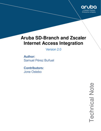
This chapter describes this switch with the following information: Front of the switch: Network ports Console port Out-of-band management (OOBM) LEDs Reset buttonBack of the switch: Power supplies and connectors Fan assemblies LED indicators for fan assemblies and power suppliesSwitch features Hardware features Software features Management softwareFront of the switch8325-48Y8C JL624A and JL625A switchesFigure 1: Front of the Aruba 8325-48Y8C (JL624A and JL625A)1254361110987Table 3: Front of the Aruba 8325-48Y8C (JL624A and JL625A)LabelDescription1Power Supply 1 and 2 (PS1/PS2), Fan, Global Status, and Unit Identification LEDs2SFP28 ports (these ports support SFP/SFP /SFP28 transceivers)3SFP28 port LEDs. For port LED detail, see “Port LEDs on the front of the switch” onpage 17.4QSFP28 port LEDsThe first port lane LED (far left) acts as the main port LED in each group of four.Post boot-up/self-test, the remaining three LEDs are not used by the switch, and should remainoff throughout the product's operation.105RJ-45 10/100/1000Base-T Out-of-Band Management Port (OOBM)6RJ-45 serial console portAruba 8325 Switch Installation and Getting Started Guide
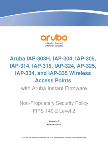
Table 3: Front of the Aruba 8325-48Y8C (JL624A and JL625A) (Continued)LabelDescription7Switch product label. Pull the tab out to view the product label information.8Micro-USB serial console port9USB-A Port for file management and HPE-Aruba Accessories10QSFP28 ports (these ports support QSFP and QSFP28 transceivers)11Reset button8325-32C JL626A and JL627A switchesFigure 2: Front of the Aruba 8325-32C (JL626A and JL627A)12438756Table 4: Front of the Aruba 8325-32C (JL626A and JL627A)LabelDescription1Power Supply 1 and 2 (PS1/PS2), Unit Identification, Global Status, and Fan LEDs2QSFP28 ports (these ports support QSFP and QSFP28 transceivers)3QSFP28 port LEDsThe first port lane LED (far left) acts as the main port LED in each group of four.Post boot-up/self-test, the remaining three LEDs are not used by the switch, and shouldremain off throughout the product's operation.4RJ-45 10/100/1000Base-T Out-of-Band Management (OOBM) Port5USB-A Port for file management and HPE-Aruba Accessories6Switch product label. Pull the tab out to view the product label information.7RJ-45 serial console port8Reset buttonChapter 2 Introducing the Aruba 8325 Switch11
Network portsTable 5: Network portsProductnumberModel nameJL624A andJL625AAruba 8325-48Y8C FB 6 F 2 PS Bdl488JL626A andJL627AAruba 8325-32C FB 6 F 2 PS Bdl–32SFP28 ports1, 3QSFP28 ports2Notes:1SFP28 ports support 1G SFP, 10G SFP , and 25G SFP28 transceivers.2QSFP28 ports support 40G QSFP and 100G QSFP28 transceivers.3For information on supported speeds, refer to “Interface-Group operation” on page 40.This product also supports optional network connectivity:Table 6: Optional network connectivity, speeds, and technologiesTransceiver form-factor and connector1SpeedTechnologyCabling1 Gbps1-Gig T210 Gbps12SFP ("miniGBIC")ConnectorSFP connectorSFP28connectorQSFP –––1-Gig SXFiber(multimode)LC––––1-Gig LXFiber(multimode orsingle mode)LC––––1-Gig LHFiber (singlemode)LC––––10-GigDirect AttachCopper(twinaxial)–––––10-Gig AOCFiber(multimode)–––––10-Gig BT3, 4Copper(twisted-pair)5–––––10-Gig SRFiber(multimode)–LC6–––10-Gig LRFiber (singlemode)–LC–––10-Gig ERFiber (singlemode)–LC–––Aruba 8325 Switch Installation and Getting Started Guide
Table 6: Optional network connectivity, speeds, and technologies (Continued)Transceiver form-factor and connector1SpeedTechnologyCabling25 Gbps25-GigDirect Attach40 Gbps100 GbpsSFP ("miniGBIC")ConnectorSFP connectorSFP28connectorQSFP ––25-Gig AOCFiber(multimode)–––––25-Gig SRFiber(multimode)––LC––25-Gig eSRFiber(multimode)––LC––25-Gig LRFiber (singlemode)––LC––40-GigDirect AttachCopper(twinaxial)–––––40-Gig AOCFiber(multimode)–––––40-Gig SR4Fiber(multimode)–––MPO7–40-Gig ESR4Fiber(multimode)–––MPO–40-Gig LR4Fiber (singlemode)–––LC–40-Gig ER4Fiber (singlemode)–––LC–40-Gig BidiFiber (singlemode)–––LC–100-GigDirect AttachCopper(twinaxial)–––––100-Gig AOCFiber(multimode)–––––100-Gig SR4Fiber(multimode)––––MPO100-Gig LR4Fiber (singlemode)––––LCChapter 2 Introducing the Aruba 8325 Switch13
Table 6: Optional network connectivity, speeds, and technologies (Continued)Transceiver form-factor and connector1Speed1 TechnologyCablingSFP ("miniGBIC")ConnectorSFP connectorSFP28connectorQSFP connectorQSFP28connectorFor supported transceivers:Go to the Aruba Support Portal at https://asp.arubanetworks.com/downloads.Filter for (1) Product Family, (2) Product Series, (3) Document File Contents.Select the ArubaOS-Switch and ArubaOS-CX Transceiver Guide link.For technical details of cabling and technologies, see “Cabling and technology information” on page 63.2RJ-45 Cat 5e cable is needed for connecting this transceiver. The max link length specified is 100m.310GBase-T transceiver limited support:-only supported in ports 1-2, 4-5, 7-8, 10-11, 13-14, 16-17. Use in any other port generates an “Incompatibleinterface” error.-maximum twelve 10GBase-T transceivers (both interface-groups 1 & 2 must be set for 10G operation).4RJ-45 shielded Cat 6A cable is needed for connecting up this transceiver. The max link length specified is 30m.5CAT6A F/FTP, S/FTP, SF/FTP highly recommended in noisy environments. Refer to ArubaSupport Advisory JL563A 10GBaseT APSC-RS20180403-01 for more information.6The Lucent Connector (LC) is a small form factor fiber optic connector.7The Multifiber Push On (MPO) connector is a 12-fiber optical connector.Management portsConsole portThe Aruba 8325-48Y8C and 8325-32C switches include an RJ-45 serial console port. This port is used to connecta console to the switch by using an RJ-45 serial cable (not supplied). A DB9-to-RJ-45 console cable can beordered from HPE: JL448A, Aruba X2C2 RJ45 to DB9 Console Cable.The 8325-48Y8C switches also include an additional Micro USB serial console port. This port can be used toconnect a console to the switch by using a standard Micro USB cable (not supplied). The Micro USB connector hasprecedence for input. If both cables are plugged in, the console output is echoed to both the RJ-45 and the MicroUSB ports, but the input is only accepted from the Micro-USB port.For more information on the console connection, see “9. Set up for initial configuration” on page 44. Theconsole can be a PC or workstation running a VT-100 terminal emulator, or a VT-100 terminal.The Aruba CX mobile app and the Aruba USB Bluetooth adapter enable you to configure your switch from yourmobile device. For information about using the Aruba CX mobile app to configure the switch, see theFundamentals Guide for your switch and software release.Out-of-band management (OOBM) portThis RJ-45 port is used to connect a dedicated management network to the switch. To use it, connect an RJ-45network cable to the management port to manage the switch through SSH or Telnet from a remote PC or a UNIXworkstation.To use this port, see the Aruba 8325 Fundamentals Guide for ArubaOS-CX. For more detailed information, refer tothe switch software manuals for your switch provided at the Aruba Support Portal athttps://asp.arubanetworks.com/downloads.14Aruba 8325 Switch Installation and Getting Started Guide
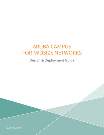
A networked out-of-band connection through the management port allows you to manage data network switchesfrom a physically and logically separate management network.USB-A portA USB-A port for file management, downloading switch software code, or use of HPE-Aruba accessories. This portuses a USB Type-A connector and complies with all USB protocols and standards.Chassis LEDs on the front of the switch Table 9 on page 16 describes the switch chassis LEDs. Table 11 on page 18 describes the switch port LEDs and their different behaviors for the JL624A and JL625A. Table 13 on page 20 describes the switch port LEDs and their different behaviors for the JL626A an JL627A.Figure 3: Chassis LEDs for the Aruba 8325-48Y8C (JL624A and JL625A)12345Table 7: Chassis LED labels for the Aruba 8325-48Y8C (JL624A and JL625A)LabelDescription1Power Supply 1 (PS1) LED2Power Supply 2 (PS2) LED3Fan LED4Global Status LED5Unit Identification LEDChapter 2 Introducing the Aruba 8325 Switch15
Figure 4: Chassis LEDs for the Aruba 8325-32C (JL626A and JL627A)12345Table 8: Chassis LED labels for the Aruba 8325-32C (JL626A and JL627A)LabelDescription1Unit Identification LED2Global Status LED3Power Supply 1 (PS1) LED4Power Supply 2 (PS2) LED5Fan LEDTable 9: Chassis LED behaviorChassis LEDsFunctionStateMeaningPS1/PS2Power supply statusOn greenPower supply is installed andoperating with all powersupplies and fans installed andno faults are present.On amberFault detected for installedpower supply, or power supplyis not receiving power.OffPower supply is not installed.On greenSystem fans are operatingnormally.On amberOne or more system fans has afault, or the minimum number offans are not installed.Fan16Fan tray statusAruba 8325 Switch Installation and Getting Started Guide
Table 9: Chassis LED behavior (Continued)Chassis LEDsFunctionStateMeaningGlobal StatusInternal power status ofthe switch.On greenThe switch has passed self-testand is powered up normally withall power supplies and fansinstalled and no faults arepresent.Flashing amber Self-test statusSwitch/port fault status UID (Unit Identification)The Unit IdentificationLED is used to help youto identify a particularunit in a rack orcollection of products.The switch initialization is inprogress during bootup.A fault or initialization failurehas occurred on the switch,one of the switch ports,power supplies, or a fan.The port LEDs with the faultwill flash simultaneously.LEDs for power suppliesand fans with a fault will beon amber.Port-speed mismatch. Atransceiver is installed in aport configured for adifferent speed.OffThe unit is not receiving power.On blue or flashing blueThe “LED locator on” commandallows you to turn on the LED.The “LED locator flashing”command will flash the LED.OffThe "LED locator off" commandturns off the LED.Port LEDs on the front of the switchFigure 5: Port LEDs for the Aruba 8325-48Y8C (JL624A and JL625A)123Chapter 2 Introducing the Aruba 8325 Switch45678917
Table 10: Port LED labels for the Aruba 8325-48Y8C (JL624A and JL625A)LabelDescription1Upper SFP28 port LED2Middle SFP28 port LED3Lower SFP28 port LED4QSFP28 port LED and lane 1 indicator5QSFP28 lane 2 LED6QSFP28 lane 3 LED7QSFP28 lane 4 LED8Out-of-band management port Link LED9Out-of-band management port Act (activity) LEDTable 11: Port LED behavior for the Aruba 8325-48Y8C (JL624A and JL625A)18Chassis LEDsFunctionStateMeaningSFP28 port LEDsTo display link andactivity information forthe port.On/flashing greenShows a valid link at 25/10 Gbps. Fast flashing1 indicates portactivity at 25 Gbps. Slow flashing2 indicates portactivity at 1 or 10 Gbps.Flashing amberWhen the Global Status LED issimultaneously flashing amber,indicates a port-speed mismatch,an incompatible, unsupported, orfaulty transceiver, or a port failure.OffPort is disabled, not connected, ornot receiving a link beat signal.Aruba 8325 Switch Installation and Getting Started Guide
Table 11: Port LED behavior for the Aruba 8325-48Y8C (JL624A and JL625A) (Continued)Chassis LEDsFunctionStateMeaningQSFP28 port LEDsTo display link andactivity information forthe port.On/flashing greenShows a valid link at 100/40 Gbps. Fast flashing1 of the Lane 1LED indicates port activity at100 Gbps. Slow flashing2 of the Lane 1LED indicates port activity at40 Gbps.Flashing amberWhen the Global Status LED issimultaneously flashing amber withthe Lane 1 LED, indicates anunsupported or faulty transceiver,or a port failure.OffPort is disabled, not connected, ornot receiving a link beat signal.Lanes 2-4 are always off and arecurrently unused by HPE-Arubasoftware.Management port LinkLEDTo display linkinformation for the port.On greenShows a valid link.OffPort is disabled, not connected, ornot receiving a link beat signal.Management port ActLEDTo display activityinformation for the port.Flashing yellowFlashing indicates port activity.1The fast flashing behavior is an on/off cycle once every 0.8 seconds, approximately.2The slow flashing behav
The Aruba 8325 switch is a multiport switch that can be used to build high-performance switched networks. The switch is a store-and-forward device offering low latency for high-speed networking. The Aruba 8325 switch also supports full network management capabilities. Table 1: Switches des