Transcription
Vetter:Pipe and Test Sealing BagsOperating ManualArt. No: 9987000801 Vetter GmbHState: 07/2007
VetterPipe and Test Sealing Bags1INTRODUCTION .1-11.1Symbols used. 1-11.2Units of measure . 1-21.3Pages . 1-31.4Figures and Tables. 1-32SAFETY INSTRUCTIONS.2-12.1General information . 2-12.2Information about the dangers. 2-22.3Warnings . 2-33CORRECT USE ACCORDING TO REGULATIONS .3-14OPERATION OF PIPE AND TEST SEALING BAGS .4-14.1Operation with controller, inflation hose and compressed air bottle . 4-14-2Operation with controller, inflation hose and other compressed airsources. 4-34-Adapters in the adapter set.4-3Air supply hose, 10m, with and without blocking valve .4-44-39987000801Operation with a foot pump having a safety valve . 4-5Vetter RDK-PDK GB-US.dociTable of ContentsTABLE OF CONTENTS
5OPERATION OF PIPE AND TEST SEALING BAGS .5-15.1Preparations for operation . 5-15.2Support structure . 5-25.3Blocking a pipeline. 5-45.4Emptying the pipeline . 5-55.5Water test and compressed air test . 5-65.6Water pressure test (open channel) . 5-65.7Compressed air test . 5-75.8Construction of a temporary bypass . 5-86MAINTENANCE AND CARE .6-16.1Maintenance intervals. 6-17VETTER SEALING BAGS .7-17.10Vetter mini-pipe sealing bags . 7-1Description .7-1Technical data.7-27.2Vetter high pressure pipe sealing bags 6 bar . 7-3Description .7-3Technical data.7-57.3Vetter float-in bags . 7-8Description .7-8Technical data.7-97.4Vetter pipe sealing bags 0.5, 1.5 and 2.5 bar . 7-10Description .7-10Technical data.7-119987000801Vetter RDK-PDK GB-US.dociiTable of ContentsVetterPipe and Test Sealing Bags
VetterPipe and Test Sealing Bags8VETTER TEST SEALING BAGS .8-18.1Vetter test sealing bags 0.5, 1.5 and 2.5 bar . 8-19VETTER BYPASS BAGS 1.5 BAR .9-19.1Description . 9-19.2Technical data . 9-210VETTER EGG PROFILE BAGS .10-110.1Vetter Egg Profile Bags 1.0 & 1.5 bar. 10-1Description .10-1Technical data.10-310.2Vetter Egg Profile Testing and Bypass bags 1.0 & 1.5 bar. 10-5Description .10-5Technical data.10-611VETTER HOUSE CONNECTION TESTING SYSTEM 2.5 BAR .11-111.1Description . 11-111.2Technical data . 11-212MATERIAL AND RESISTANCE CHARTS.12-112.1Material chart. 12-112.2Temperature resistance. 12-112.3Resistance chart. 12-29987000801Vetter RDK-PDK GB-US.dociiiTable of ContentsDescription .8-1Technical data.8-2
VetterPipe and Test Sealing Bags1I NTRODUCTIONThe precondition for the safe use and the defect-free operation of Vetter pipe andtest sealing bags is the knowledge and the observance of this operating manualas well as the safety instructions.NoteDIN 7716 is to be adhered to in cases of long-term storage.1.1IntroductionIn addition to this, the pertinent work protection regulations, work safetyregulations and accident prevention regulations are to be observed the same asthe generally recognized technology lawsSymbols usedThe following symbols are used in the text for dangers and warnings:This symbol means that there is imminent danger. If it is notavoided then death or serious injury will result.This symbol means that there is a possible dangeroussituation. If it is not avoided then death or serious injury couldresult.9987000801Vetter RDK-PDK GB-US.doc1-1
VetterPipe and Test Sealing BagsIntroductionThis symbol means that there is possibly a dangeroussituation. If it is not avoided then light injuries or slight injuriescould result.This symbol means that there is the possibility of damagebeing caused. If it is not avoided then the product orsomething else in its vicinity could be damaged.The following symbols are used in the text to explain handling instructions:1.2 Indicates enumeration.ÖThis means the "task to be carried out".9This means the "task is completed".ªThis means "follow an executed task". This means "a monitored task". This means an "important statement".Units of measureAll units are specified in millimetre "mm".All angles are specified in degrees " ".Other units of measure are specially marked.9987000801Vetter RDK-PDK GB-US.doc1-2
VetterPipe and Test Sealing Bags1.3PagesThe pages in this operating manual are arranged in numerical order chapter bychapter.Page 1-2 means: Chapter 1, Page 2.1.4Figures and TablesAll figures in this operating manual are arranged in numerical order chapter bychapter.IntroductionFigure 3-5 means: Chapter 3, Figure 5.All tables in this operating manual are arranged in numerical order chapter bychapter.Table 4-2 means: Chapter 4, Table 2.9987000801Vetter RDK-PDK GB-US.doc1-3
VetterPipe and Test Sealing Bags2S AFETY INSTRUCTIONSThe knowledge and observance of this operating manual are the preconditionsfor the use of Vetter pipe and test sealing bags.2.1General informationSafety instructionsThe observance of all pertinent work protection regulations and safetyregulations, accident prevention regulations (e.g. safety regulations from thetechnical authorities – TBG) as well as the recognized technical laws are to becarried out.The pipeline is to be inspected for damage before using pipe and test sealingbags. The area in the pipe for the pipe and test sealing bag must be free ofdeposits, dirt and foreign bodies, such as fragments, sharp-edged objects etc.Necessary personal protection devices must be made available: protectionclothing, cloves, helmets, facial and/or eye protection etc.Pipe and test sealing bags must be positioned full length in the pipeline and withthe sealing area on the inside wall of the pipe.All pipe and test sealing bags (round and egg-shaped) must be non-positivelyand positively positioned and fitted.9987000801Vetter RDK-PDK GB-US.doc2-1
VetterPipe and Test Sealing Bags2.2Information about the dangersOperation of Vetter pipe bags, test bags and bypass bags areonly permitted with original Vetter inflation fittings andinflation hoses. Parts made by another manufacturer caninfluence safety.Pipe and test sealing bags are made of a strong expandingmaterial. If this material is expanded beyond its permittedmaximum range then this can cause bursting.No person is allowed to remain within the working area duringthe pressure test.With a water pressure test, the pipeline being tested must nothave any direct connection to a high-pressure line (e.g.hydrant).After positioning the pipe and/or the test sealing bag it is tobe ensured that nobody remain in the channel or in front ofthe pipe during inflation, as well as during the test procedureand emptying sequence.Before removing the set-up make certain that the pipeline isnot under any pressure and is completely empty.9987000801Vetter RDK-PDK GB-US.doc2-2Safety instructionsChanges and modifications to the sealing bags, inflationfittings and inflation hoses are not permitted.
VetterPipe and Test Sealing Bags2.3WarningsOutside the pipeline, Vetter pipe and test sealing bags, 0.5bar and 1.0 bar, must only be filled to maximum 0.2 bar forthe visual test. 1.5 bar and 2.5 bar bags must only be filled toa maximum of 0.5 bar.All controllers are fitted with a safety valve that has apermitted maximum operating pressure corresponding to thepipe and test sealing bag.If the maximum operating pressure of 0.5, 1.5, 2.5 or 6 bar isexceeded then the safety valve will activate. The tolerance foropening and closing of the safety valve is only permitted to bea maximum of 10%. The set pressure must not bechanged.If the sealing on the top part of the valve is removed then itsoperation is no longer guaranteed and the safety valve mustbe exchanged. The permitted inlet pressure on the controller(marking on the inlet coupling) must not be exceeded.9987000801Vetter RDK-PDK GB-US.doc2-3Safety instructionsThe pipe and test sealing bags as well as the accessoriesmust be checked for perfect condition before and after eachoperation.
VetterPipe and Test Sealing Bags3C ORRECT USE ACCORDING TOREGULATIONSInflation with inflation fittings from another manufacturer is classified as contraryto the regulations for correct use.They are exclusively used for blocking the intended pipes, for leak sealing testingof pipelines and for construction of a bypass.Any other application or use going beyond this is classified as contrary to theregulations for correct use.An application contrary to the regulations for correct use of Vetter pipe and testsealing bags includes: Incorrect use, operation or maintenance of pipe and test sealing bags. Use of the Vetter pipe and test sealing bags with defective safetydevices or incorrectly fitted or non-functional inflation fittings. Non-observance of the instructions given in the operating manualconcerning storage, operation and maintenance of pipe and test sealingbags. Insufficient monitoring of accessory parts subject to wear. Incorrectly carried out maintenance work.Correct use according to regulations also includes9987000801 The observance of all instructions given in this operating manual. The observance of the set periods for maintenance and care specified inthe chapter "Maintenance and Care".Vetter RDK-PDK GB-US.doc3-1Correct use according to regulationsVetter pipe and test sealing bags must, depending on the purpose of the task,only be inflated with compressed air to the corresponding pressure level usingoriginal inflation fittings.
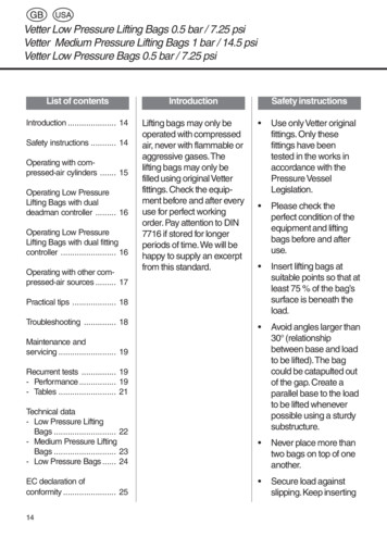
VetterPipe and Test Sealing Bags4O PERATION OF PIPE AND TEST SEALINGBAGS 4.1Observe the corresponding pressure level with operation of pipe and testsealing bags.Operation with controller, inflation hose andcompressed air bottleNoteIn the following presented figures the sequence of events uses thepressure level of 2.5 bar as an example.The corresponding bags and accessories must be used for otherpressure levels and other sources of air.Pipe and test sealing bagsStep 1:Connect pipe and test sealing bags2.5 bar to the inflation hose.Inflation hoseStep 2:Connect the inflation hose to thecontroller.Inflation hose 2.5 bar, 10m, grey(example)9987000801Vetter RDK-PDK GB-US.doc4-1Operation of pipe and test sealing bagsThis chapter informs you about which compressed air sources you can use withthe Vetter pipe and test sealing bags.
VetterPipe and Test Sealing BagsThe inflation hose, the sealing bag andthe controller must have the samepressure level.Step 3:Connect the connection hoseof the pressure regulator to the inletcoupling of the controller.In doing this it is imperative that thepermitted inlet pressure of thecontroller is observed.Single controller 2.5 bar, fitting(example), having the same pressurelevel as the inflation hosePressure regulatorStep 4:Screw-in the connection threadof the pressure regulator into theinside thread of the valve on thecompressed air bottle.Pressure regulator 200/300 bar(example)Compressed air bottle(Example)9987000801Vetter RDK-PDK GB-US.doc4-2Operation of pipe and test sealing bagsController
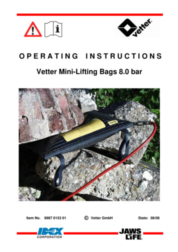
VetterPipe and Test Sealing BagsOperation with controller, inflation hose and othercompressed air sources Observe the maximum inlet pressure from the compressed air source forthe different pressure levels (refer to the table below).Applied pressure levelOperation of pipe and test sealing bags4.2Maximum inlet pressureof the compressed air source0.5 bar2 bar1.0 bar2 bar1.5 bar2 bar2.5 bar4 barAdapters in the adapter setThe adapter set contains adapters for the following air sources:Truck compressed air connectionand dummy couplingTruck compressed air connectionClose the control line with the dummycoupling.Dummy coupling9987000801Vetter RDK-PDK GB-US.doc4-3
VetterPipe and Test Sealing BagsLocal compressed air networkConnection on the output coupling ofa compressed air network.Operation of pipe and test sealing bagsTruck tyre valveFor inflation with a normal hand pumpor foot pump.Truck tyre valve connectionFor taping off air from a spare wheel.Hand pump and foot pumpHand pump or foot pump with 2mconnection hose to the connectiononto the inlet coupling of a controller.Hand pump and foot pump do notbelong to the delivery package of theadapter set.Air supply hose, 10m, with and without blocking valveThe air supply hoses, with andwithout blocking valve, can be usedas an extension between the airsource and the controller.Blocking valve9987000801Vetter RDK-PDK GB-US.doc4-4
VetterPipe and Test Sealing Bags4.3Operation with a foot pump having a safety valveFoot pump 1.5 bar or 2.5 bar withsafety valveFoot pump 1.5 bar with safety valveOperation of pipe and test sealing bagsFoot operated air pump, 1.5 bar or2.5 bar, with safety valve and 2mconnection hose for inflation ofsealing bags in connection with aninflation hose.Foot pump 2.5 bar with safety valve9987000801Vetter RDK-PDK GB-US.doc4-5
VetterPipe and Test Sealing Bags5O PERATION OF PIPE AND TEST SEALINGBAGS 5.19987000801When using the pipe and test sealing bags, observe the safetyinstructions given in Chapter 2 as well as the pertinent regulations forwork protection and safety protection, accident prevention regulations(e.g. the safety regulations of the technical authorities – TGB) and thegenerally recognized laws of technology.Preparations for operation Ensure that only authorized staff are in the working area and dangerarea.ÖSelect a suitable pipe and/or test sealing bag which corresponds to therequirements. Check the bag and the accessories to be used for completeness anddamage. Damaged bags and damaged accessory parts must not be used! The bag diameter must be smaller than the inside diameter of thepipeline.9Inflation hose and controller must already be connected to the sealingbag.ÖMark the working area.ÖPosition the bag (full length) into the pipe. The sealing bag in the pipe is to be supported.ÖDraw the sealing bag to the support structure and inflate so that it canstill be moved in the pipeline.ÖSecure the sealing bag with a securing line in order to avoid the bagslipping back when deflated. The support structure should be made so that the sealing bag can besupported over a large area.ÖLeave the shaft and/or pipeline. Make certain that no staff remain in the area of danger.Vetter RDK-PDK GB-US.doc5-1Operation of pipe and test sealing bagsIn this chapter you will find out how the Vetter pipe and test sealing bags areapplied.
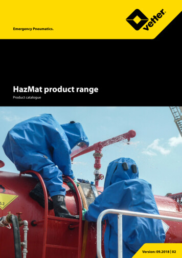
VetterPipe and Test Sealing BagsInflate the sealing bag to the permitted maximum operating pressurefrom a safe position.There is a danger of the bag catapulting outwards.The pressure or water column must be completely reducedwithin the pipeline before the support structure is removed.Otherwise the sealing bag could catapult outwards.After completion of the work, pressure reduction is to becarried out via the inflation hose (ventilation nipple) or thecontroller (pressure reduction via the knurled screw of thesafety valve).Generally this must be made outside the pipeline or shaft.5.2ÖIf the water has completely flowed out of the shaft / pipeline then releasethe compressed air out of the bag.ÖNow remove the support structure and take the bag out of the shaft /pipeline.Support structureThe type of support structure depends on the structural factors in the pipe, thepipe itself and the counter-pressure to be expected. The following supportpossibilities are only drawing diagrams and are given as examples.General details of support(presented as a diagram)1 Bag centre2 Inflatable bag sleeve9987000801Vetter RDK-PDK GB-US.doc5-2Operation of pipe and test sealing bagsÖ
VetterPipe and Test Sealing BagsSupport suggestion for a ditchOperation of pipe and test sealing bags(presented as a diagram)Support suggestion for a streetinlet shaft(presented as a diagram)Support suggestion for a pipeopening on the outside wall(presented as a diagram)1 Outside wall with pipe opening9987000801Vetter RDK-PDK GB-US.doc5-3
VetterPipe and Test Sealing BagsBlocking a pipelineThe support structure of a pipeline under pressure mustnever be removed.Pipe sealing bags and test sealing bags could suddenlycatapult outwards.During a pressure test nobody is permitted to remain in the
Pipe and Test Sealing Bags 9987000801 Vetter_RDK-PDK_GB-US.doc 3-1 Correct use according to regulations 3 CORRECT USE ACCORDING TO REGULATIONS Vetter pipe and test sealing bags must, depending on the purpose of the task, only be inflated with compressed air to the corres