Transcription
AIR FORCE HANDBOOK 10-222, VOLUME 26 February 2012BARE BASE ASSETSDEPARTMENT OF THE AIR FORCE
BY ORDER OF THESECRETARY OF THE AIR FORCEAIR FORCE HANDBOOK 10-222VOLUME 26 February 2012OperationsBARE BASE ASSETSACCESSIBILITY: Publications and forms are available on the e-Publishingwebsite at www.e-publishing.af.mil for downloading or ordering.RELEASABILITY: There are no releasability restrictions on this publication.OPR: AFCESA/CEXXSupersedes AFH 10-222V2,1 April 2006Certified by: AF/A7CX(Colonel Darren P. Gibbs)Pages: 128This handbook describes Basic Expeditionary Airfield Resources (BEAR) AirForce civil engineers are likely to site, install, or operate in an expeditionaryfield environment. It provides a brief overview of major systems and equipment,along with applicable technical references. Users must refer to specificequipment technical orders for siting, installation, operation and maintenanceinformation. This publication applies to all Air Force active duty, Air NationalGuard (ANG), and Air Force Reserve Command (AFRC) Civil Engineer units.It supports Air Force Instruction (AFI) 10-209, RED HORSE Program; AFI 10210, Prime Base Engineer Emergency Force (BEEF) Program and AFI 10-211,Civil Engineer Contingency Response Planning. Refer recommended changesand questions about this publication to the office of primary responsibility usingthe AF Form 847, Recommendation for Change of Publication: route AF Form847s from the field through the appropriate functional chain of command andMajor Command (MAJCOM) publications/forms managers. Ensure that allrecords created as a result of processes prescribed in this publication aremaintained according to AFMAN 33-363, Management of Records, anddisposed of in accordance with the Air Force Records Disposition Schedule(RDS) located at m. The useof the name or mark of any specific manufacturer, commercial product,
AFH10-222 Volume 2, 6 February 20122commodity, or service in this publication does not imply endorsement by the AirForce.SUMMARY OF CHANGESThis document is substantially revised and must be completely reviewed. Thisrevision deletes outdated information and updates changes to BasicExpeditionary Airfield Resources (BEAR), including the addition of the BEARWater System, 130K Portable Heater, Interim Power Unit (IPU), and the MEP805B and MEP-806B Tactical Quiet Generators. Also, as a result of ongoingchanges to BEAR equipment configurations, new BEAR Order of Battle (BOB)Unit Type Codes (UTC) were added, and users are encouraged to seek currentinformation from the UTC Management or Manpower and Equipment ForcePackaging (MEFPAK) Community of Practice (CoP) or see their UnitDeployment Manager (UDM).Chapter 1—INTRODUCTION. 111.1. General Information . 111.2. Overview . 11Figure 1.1. Air Force Civil Engineer Publications Hierarchy . 121.3. Roles and Responsibilities . 13Table 1.1. BEAR Roles and Responsibilities . 131.4. BEAR Accountability . 15Figure 1.2. Logistics Personnel Help Keep Track of BEAR Assets . 161.5. Equipment Packaging and Configurations . 17Figure 1.3. BEAR Reconfiguration . 17Table 1.2. BOB Air and Surface Equipment UTCs . 181.6. Equipment Repairs . 201.7. Additional Information . 20
AFH10-222 Volume 2, 6 February 20123Chapter 2—SHELTERS . 202.1. General Information . 21Figure 2.1. Erecting Shelters at Forward Operating Location . 212.2. BEAR Shelters . 21Figure 2.2. Small Shelter System . 22Table 2.1. SSS Environmental Limitations . 22Figure 2.3. Medium Shelter System . 23Table 2.2. MSS Environmental Limitations . 23Figure 2.4. Bare Base Dome Shelter . 24Table 2.3. Dome Shelter Environmental Limitations . 24Figure 2.5. Large Area Maintenance Shelter . 25Table 2.4. LAMS Environmental Limitations . 252.3. Legacy Shelters . 26Figure 2.6. Frame-Supported Tensioned Fabric Shelter . 26Table 2.5. FSTFS Environmental Limitations. 26Figure 2.7. General Purpose Shelter . 27Table 2.6. GP Shelter Environmental Limitations . 27Figure 2.8. Expandable Shelter Container . 28Table 2.7. ESC Environmental Limitations. 28Figure 2.9. Aircraft Maintenance Hangar . 29Table 2.8. ACH Environmental Limitations . 29Figure 2.10. Tent Extendable Modular Personnel . 30Table 2.9. TEMPER Environmental Limitations . 30
AFH10-222 Volume 2, 6 February 20124Chapter 3—WATER AND SANITATION . 313.1. General Information . 313.2. BEAR Water System . 31Figure 3.1. 1500 ROWPU . 32Table 3.1. 1500 ROWPU Particulars . 32Figure 3.2. 20,000-Gallon Fabric Water Tank. 33Table 3.2. 20,000-Gallon Tank Characteristics and Information . 33Figure 3.3. 3,000-Gallon Fabric Water Tank. 34Table 3.3. 3,000-Gallon Tank Characteristics and Information . 34Figure 3.4. 400-GPM Diesel Pump Assembly . 35Table 3.4. 400-GPM Diesel Pump Characteristics . 35Figure 3.5. 35-GPM Electric Pump Assembly . 36Table 3.5. 35-GPM Electric Pump Assembly Characteristics . 36Figure 3.6. 125-GPM Diesel Pump Assembly . 37Table 3.6. 125-GPM Diesel Pump Characteristics . 37Figure 3.7. Dual Pump Station . 38Table 3.7. Dual Pump Station Characteristics . 38Figure 3.8. Bladder Water Level Controller . 39Table 3.8. Bladder Water Level Controller Characteristics . 39Figure 3.9. Sewage Ejector System (Latrine) . 40Table 3.9. Sewage Ejector System (Latrine) Characteristics. 40Figure 3.10. Sewage Ejector Lift Station (Kitchen) . 41Table 3.10. Sewage Ejector Lift Station (Kitchen) Characteristics . 41
AFH10-222 Volume 2, 6 February 20125Figure 3.11. Dual Pump Life Station . 42Table 3.11. Dual Pump Lift Station Characteristics . 42Figure 3.12. Macerator Pump Life Station . 43Table 3.12. Macerator Pump Lift Station Characteristics . 43Figure 3.13. Wastewater Collection Tank with Aeration System . 44Table 3.13. Wastewater Collection Tank System Characteristics . 44Figure 3.14. Water System Hoses, Connector and Valves . 453.3. BEAR Sanitation Assets . 45Figure 3.15. Shower/Shave Unit. 46Figure 3.16. Latrine Unit . 47Figure 3.17. Waste Disposal Trailer . 47Figure 3.18. SHL System Components . 48Chapter 4—MOBILE ELECTRIC POWER AND DISTRIBUTION . 494.1. General Information . 49Figure 4.1. Establishing Deployed Power Plant . 494.2. MEP-805B TQG . 50Figure 4.2. MEP-805B Generator. 50Table 4.1. MEP-805B Generator Characteristics . 504.3. MEP-806B TQG . 51Figure 4.3. MEP-806B Generator. 51Table 4.2. MEP-806B Generator Characteristics . 514.4. MEP-012A Prime Power Generator . 52Figure 4.4. MEP-012A Generator . 52
AFH10-222 Volume 2, 6 February 20126Table 4.3. MEP-012A Generator Basic Characteristics . 524.5. Interim Power Unit . 53Figure 4.5. Interim Power Unit . 53Table 4.4. IPU Basic Characteristics . 534.6. Generator Fuel Bladders . 54Figure 4.6. Collapsible Fuel Bladder . 544.7. Electrical Distribution Systems. 54Figure 4.7. Primary Switching Center (DRS Radian Model) . 55Table 4.5. PSC Characteristics . 55Figure 4.8. Secondary Distribution Center (Radian Model) . 56Table 4.6. SDC Characteristics . 56Figure 4.9. 25KW Power Distribution Panel (Radian Model). 57Table 4.7. PDP Characteristics (25KW). 57Figure 4.10. 60KW Power Distribution Panel (Radian Model). 58Table 4.8. PDP Characteristics (60KW). 58Figure 4.11. Primary Electrical Distribution Cable and Reel . 59Figure 4.12. Typical Secondary Electrical Distribution Cables. 60Table 4.9. Approximate Voltage Drops . 604.8. Legacy Power Systems . 61Table 4.10. Characteristics of Legacy Generators . 61Figure 4.13. Secondary Distribution Center (Model JEU-191E). 62Table 4.11. SDC Characteristics (Model JEU-191E) . 62
AFH10-222 Volume 2, 6 February 20127Chapter 5—HEATING, VENTILATION, AIR CONDITIONING, ANDREFRIGERATION (HVAC/R) .635.1. General Information . 635.2. Field-Deployable Environmental Control Unit (FDECU) . 63Figure 5.1. FDECU. 63Table 5.1. FDECU Characteristics . 645.3. 130K Portable Heater. 64Figure 5.2. 130K Portable Heater . 65Table 5.2. 130K Portable Heater Characteristics . 655.4. H-1 Heater Unit . 66Figure 5.3. H-1 Heater . 66Table 5.3. H-1 Heater Characteristics . 665.5. M-80 Water Heater . 67Figure 5.4. M-80 Water Heater . 67Table 5.4. M-80 Water Heater Characteristics . 675.6. WH-400 Water Heater . 68Figure 5.5. WH-400 Water Heater . 68Table 5.5. WH-400 Water Heater Characteristics . 685.7. Advanced Design Refrigerator, 300 Cubic Foot (ADR-300) . 69Figure 5.6. ADR-300 . 69Table 5.6. ADR-300 Characteristics . 695.8. TRICON Refrigerated Container System (TRCS) . 70Figure 5.7. TRICON Refrigerated Container System. 70
AFH10-222 Volume 2, 6 February 20128Table 5.7. TRCS Characteristics . 705.9. Legacy HVAC/R Systems . 71Figure 5.8. ECU-39 . 71Figure 5.9. 1200-CF Refrigeration Unit . 72Figure 5.10. 150-CF Refrigeration Unit . 72Chapter 6—SPECIALIZED ASSETS . 736.1. General Information . 736.2. Specialized Equipment and Systems. 73Figure 6.1. Remote Area Lighting System (RALS) . 73Figure 6.2. TF-2 Light Cart . 74Figure 6.3. Laying AM-2 Matting at Deployed Location . 74Figure 6.4. Moving Heavy Rolls of Concertina Wire. 75Figure 6.5. MC-2A Diesel-Driven Air Compressor . 75Figure 6.6. EALS Temporary Airfield Lights . 76Table 6.1. EALS II Modules . 77Figure 6.7. Mobile Aircraft Arresting System . 78Figure 6.8. Single Pallet Expeditionary Kitchen (SPEK) . 79Figure 6.9. BEAR 550 Kitchen (550-Personnel) . 80Chapter 7—NON-BEAR ASSETS . 817.1. General Information . 817.2. Fuels Operational Readiness Capability Equipment(FORCE) . 81Figure 7.1. R-18 Trailer-Mounted Pumping Unit . 82
AFH10-222 Volume 2, 6 February 20129Figure 7.2. R-19 Trailer-Mounted Filter Separator . 82Figure 7.3. R-20 Multi-Aircraft Servicing Platform . 83Figure 7.4. R-21 Portable Hydrant Mission Support Plumbing Assy . 84Figure 7.5. Tactical Automated Service Station (TASS) . 847.3. Fuels Mobility Support Equipment (FMSE) . 85Figure 7.6. R-14 Transportable Hydrant Refueling System . 85Figure 7.7. R-22 Trailer-Mounted Transfer Pump . 86Figure 7.8. FFU-15E Skid-Mounted Filter Separator . 86Figure 7.9. GRU-17E Aircraft Fuel-Servicing Unit . 87Figure 7.10. PMU-27M Pumping Assembly . 887.4. Fuel Bladders . 88Figure 7.11. Fuel Bladders in Storage and Distribution Area. 88Table 7.1. Collapsible Fuel Bladder Details . 897.5. Expeditionary Medical Support (EMEDS) Facilities . 90Figure 7.12. Expeditionary Medical Support Facility . 907.6. Aeromedical Staging Facility (ASF). 917.7. Transportable Blood Transshipment Center (TBTC). 91Figure 7.13. Patient Evacuation at Aeromedical Staging Facility . 927.8. Navigational Aids (NAVAIDs) . 92Figure 7.14. Landing Control Central Surveillance Radar System. 93Figure 7.15. Mobile Control Tower. 94Figure 7.16. Mobile Microwave Landing System . 95Figure 7.17. Tactical Air Navigation Unit . 95
AFH10-222 Volume 2, 6 February 2012107.9. International Organization for Standardization (ISO)Containers . 967.10. Expandable Light Air Mobile Shelter (ELAMS) . 96Figure 7.18. Expandable Light Air Mobile Shelter . 96Table 7.2. ELAMS Environmental Limitations . 967.11. K-Span Structures . 97Figure 7.19. K-Span Facility Under Construction . 977.12. Revetments . 97Figure 7.20. B-1 Revetments Layout Plan and Elevation(16-Feet High) . 987.13. Force Provider Facilities and Equipment . 99Figure 7.21. Force Provider Assets . 99Attachment 1—GLOSSARY OF REFERENCES ANDSUPPORTING INFORMATION . 100Attachment 2—ENGINEER REACHBACK AND OTHER USEFULLINKS . 111Attachment 3—BEAR AIR-CONFIGURED UTC DETAILS . 112
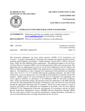
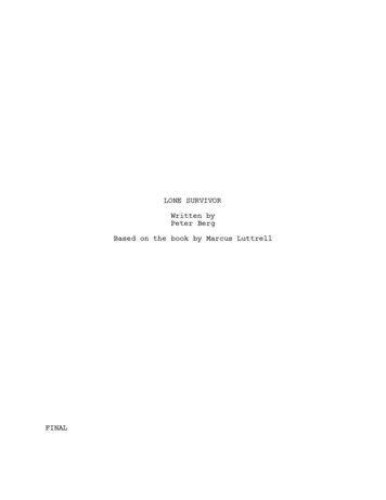
AFH10-222 Volume 2, 6 February 201211Chapter 1INTRODUCTION1.1. General Information. Long before World War II, leaders in the Army AirForces recognized the importance of being able to rapidly construct and sustainairfields close to or even behind enemy lines. Over the years, that fundamentalunderstanding of projecting air power precipitated doctrine, organization,training, materiel, leadership and education, personnel, and facilities(DOTMLPF) that continues to evolve today. The Air Force’s power projectionmission requires that it be able to apply air, space, and cyberspace poweranywhere in the world in support of U.S. national interests. In fact, air, space,and cyberspace power can reach across the full spectrum of militaryoperations—from humanitarian assistance missions and stability operations, tothe decisive application of air power in support of combat operations around theglobe. To that end, the ability to develop a bare base or operating locationquickly is an essential part of the USAF power projection mission, andsubsequently one of civil engineers’ (CE) most important expeditionary andcontingency tasks.1.2. Overview. Like most major construction projects, developing a bare base oroperating location to beddown forces require both skilled personnel and suitablemateriel to build facilities and infrastructure. Basic Expeditionary AirfieldResources (BEAR) and other assets help fulfill the latter requirement. BEAR isessentially war readiness materiel that is configured and stored ready to deploy.This handbook primarily addresses BEAR assets used during bare basedevelopment and force beddown activities. It contains CE tactics, techniques,and procedures (TTPs) that follow the precepts outlined in Air Force DoctrineDocument (AFDD) 4-0, Combat Support, and AFDD 3-34, EngineerOperations, and aids in the implementation of Air Force Policy Directive(AFPD) 10-2, Readiness. This relationship is illustrated in the Air Force CEhierarchy of publications (Figure 1.1.). Prime Base Engineer Emergency Force(Prime BEEF) team leaders, supervisors, and work crews may find thishandbook useful during bare base development or beddown operations usingBEAR and non-BEAR deployment assets.
AFH10-222 Volume 2, 6 February 2012Figure 1.1. Air Force Civil Engineer Publications Hierarchy.12
AFH10-222 Volume 2, 6 February 2012131.3. Roles and Responsibilities. Several organizations have important roles andresponsibilities for the development, management, and maintenance of BEAR.Some of them are listed in Table 1.1. See AFI 25-101, War Reserve Materiel(WRM) Program Guidance and Procedures, for a more complete list of BEARroles and responsibilities.Table 1.1. BEAR Roles and Responsibilities.AgencyRoles and ResponsibilityGeneral OfficerSteering Group(GOSG)GOSG is chaired by ACC/A4. Principal membersinclude AF/A4/7P; AF/A7C; AF/A4/7Z; WR-ALC/CC, AF/A4L; USAFE/A4; PACAF/A4; AMC/A4;AFSVA/CC; AFMC/A4; AFSOC/A4; and AETC/A4.The GOSG provides executive oversight, policy, andguidance to the BEAR program.BEAR SystemsReadiness Board(BSRB)BSRB is an O-6 level multi-agency managementboard chaired by ACC/A4R. The board is responsiblefor oversight of the BEAR program and providesguidance and direction to the BEAR IntegratedProcess Team (BIPT).BIPT is an action officer level, multi-agency, workinggroup chaired by ACC/A4RX. The BIPT isBEAR Integratedresponsible for managing daily activities involvingProcess Team (BIPT)system requirements, configuration, modernization,sustainment, and resource programming.Air CombatCommand/GlobalManager and AFExecutive AgentAs Global Manager, ACC/A4 plans, programs,advocates, justifies, and defends current and out-yearfunding through the corporate process for replacementand modernization of existing BEAR systems andequipment for Using Commands and authorizedtraining requirements.
AFH10-222 Volume 2, 6 February 201214Table 1.1. (Continued)Develops contingency planning factors,infrastructure requirements, and conceptual planningguidance for engineers, planners, and developers ofAir Force CivilBEAR. Evaluates adequacy of BEAR Systems andEngineer Supportrecommends changes or improvements to the BIPTAgency (AFCESA)/BSRB. Develops training standards and curriculumfor Silver Flag exercise sites for training personnelon selected BEAR Systems.Develops and maintains standard manpower andLogistics Detail (LOGDET) for every BEAR UnitType Code (UTC) based on the mission capability ofthe UTC. Evaluates packaging options and resources(pallets, nets, cargo bins, etc.) for BEAR UTCs and49th Materielshipping increments to ensure the most efficientMaintenance Group packaging methods are used to optimize thedeployment footprint. Also coordinatesrecommended changes to LOGDET with the otherBEAR storing and using commands and preparenecessary LOGMOD transactions to reflect acceptedchanges.Storing CommandPrograms and budget for acquisition of expendableassets and the storage and maintenance of all WRMfor bases they have host base responsibility. ReportWRM serviceability and availability in accordancewith (IAW) Air Force Status of Resources andTraining System (SORTS). Coordinate with UsingCommands to redistribute/dispose of assets tosupport force employment or beddown changes, andidentify and redistribute excess WRM to fill theircommand shortages and other command WRMshortfalls.
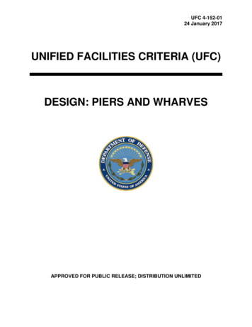
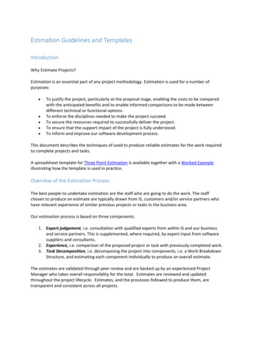
AFH10-222 Volume 2, 6 February 201215Table 1.1. (Continued)Using CommandDetermines WRM prepositioning requirements tosupport the War and Mobilization Plan (WMP-4) andprogram for initial and replacement WRM SupportEquipment (SE) requirements. Responsible fornotifying Storing Commands of out-of-cycle WRMrequirement adjustments due to operation plan(OPlan)/concept plan (CONPlan) changes. Identifybeddown requirement changes and notify StoringCommands when WRM assets are no longer requiredor are in excess of determined requirement.1.4. BEAR Accountability. Accurate accountability is key to successfuldeployment, reception and sustainment of BEAR assets. Proper supplydiscipline must be maintained for the duration of deployments. Below are somecommon factors for tracking and maintaining BEAR assets. See AFI 25-101,and command guidance for specific accountability requirements.1.4.1. Upon equipment transfer, the contingency site civil engineer squadron hasoverall accountability and responsibility for maintaining BEAR assets.According to AFI 25-101, engineer squadron commanders should signappropriate documentation and assume responsibility of BEAR equipmentassets. When deployed to support theater activities, 49th Materiel MaintenanceGroup (MMG) personnel and other AF logistics personnel deployed in directsupport of BEAR assets assist CE commanders in tracking assets and assigningresponsibility to major users (Figure 1.2.).1.4.2. In addition, BEAR Mobility Readiness Spares Packages (MRSP) will betransferred, before each deployment, to the 440th Supply Chain OperationsSquadron (440 SCOS), in accordance with AFMAN 23-110, Volume II, Part 2,Chap 26. Transferred MRSPs will be under the control of the contingency siteLogistics Readiness Squadron (LRS) until returned to home station. Logisticspersonnel also account for all BEAR ISO containers using the Army ContainerAsset Management System (ACAMS), according to AFI 24-203, Preparationand Movement of Air Force Cargo.
AFH10-222 Volume 2, 6 February 201216Figure 1.2. Logistics Personnel Help Keep Track of BEAR Assets.1.4.3. When BEAR assets are transferred to other services/agencies, they will behandled IAW AFMAN 23-110, Volume II, Part 2, Chapter 22.1.4.4. All fuel and water bladders should be transferred to the contingency CEsquadron commander at the time of deployment. These items are not normallyreconstituted after deployment.1.4.5. A variety of options exist to redeploy BEAR assets, including a BEARReconstitution Team (UTC XFAJ1), contractor personnel, or CE personnel. Thegoal is an orderly breakdown of BEAR assets so they can be redeployed andreconstituted as quickly as possible—important processes to ensure BEARfuture contingency operations readiness.1.4.6. During redeployment preparations, the contingency site BCE and XFAJ1supply personnel conduct a joint inventory and review accountabledocumentation. The contingency site BCE must be relieved of accountabilitybefore redeploying.1.4.7. Following contingency use, reconstitution is generally conducted for allBEAR equipment, vehicles, and MRSPs by the storing MAJCOM.
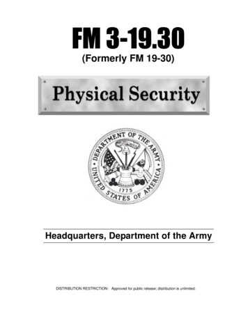
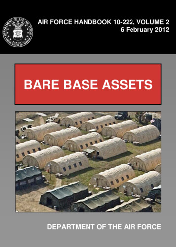
AFH10-222 Volume 2, 6 February 2012171.5. Equipment Packaging and Configurations. In recent history, bare basebeddown and sustainment equipment has undergone significant changes to theway it is packaged and configured for deployment. Equipment sets formerlyknown as Harvest Eagle and Harvest Falcon transitioned to BEAR equipmentand housekeeping sets. Today, these BEAR sets are being converted tocapabilities-based UTC packages under the BEAR Order of Battle (BOB)concept (Figure 1.3.). The goal is to further refine the priority and sequencing ofdelivered assets and make improvements in equipment configurations that createefficiencies and enhance flexibility and responsiveness. Although, the majordifference between these new air- and surface-configured BOB UTCs (Table1.2.) is packaging, equipment contents do vary between some of them. Usersshould refer to appropriate UTC Management or Manpower and EquipmentForce Packaging (MEFPAK) databases or see their Unit Deployment Manager(UDM) for current information.Figure 1.3. BEAR to BOB Reconfiguration.
AFH10-222 Volume 2, 6 February 201218Table 1.2. BOB Air and Surface Equipment UTCs.AirConfiguredUTC JXFACLASSETCombat Air Forces (CAF) Initial (8 Medium/8Small Shelters)Low Voltage Industrial (2 MEP-806's)Water Distribution InitialWater Distribution Follow-OnEngineering Management (2 Small Shelters)Power Pro/CE Sup/Elect (3 Small Shelters)TF-2 Lightcart (2 TF-2's)Mobility Air Forces (MAF) Initial (6 Medium/8Small Shelters)4K Dome (1 Shelter)Field-Deployable Environmental Control Unit(FDECU), 12 Ea.8K Dome (1 Shelter)AM2 Matting (6 Bundles)Billeting (12 Small Shelters)CAF Add-On (2 Medium/1 Small Shelter)CAF Follow-On (4 Small Shelters)Tactical Exchange (1 Small Shelter)Entomology (No Facility)Fire Ops/Crash Rescue (4 Small Shelters)Advanced Design Refrigerator,300 CF (ADR-300), 1 Ea.Large Are
This handbook describes Basic Expeditionary Airfield Resources (BEAR) Air Force civil engineers are likely to site, install, or operate an expeditionary in . handbook useful during bare base development or beddown operationsusing BEAR