Transcription
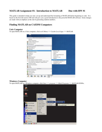
Experiment 11: MATLAB with ArduinoPart1: Introduction to ARDUINO/SIMULINKLab Objectives Install and verify Arduino software package for Simulink using a digital output to light a LEDCommunicate with the target board (Arduino) using external mode by changing the brightnessof an LED with PWMPart 1: Arduino Toolbox Installation for SimulinkObjective: Install and verify Arduino software package for Simulink using a digital output to light a LEDSimulink Arduino Library Installation: Open MATLAB2013a(b)/MATLAB 2014a and type “targetinstaller” in the MATLAB commandwindow.The target installer window will appear. Select “Install from Internet”.Select “Arduino (Arduino Uno/Nano/Mega 2560 for Matlab 2014a)” and click “Next”When prompted, log in using your MathWorks credentials. If you do not have an account youwill need to create one.Follow the onscreen prompts to install the library.Once the installation processis finished, you can exit out by clicking on“Finish”.Arduino Mega 2560 Drivers’ Setup: Connect your Arduino Mega board to the computer using the USB cable. Your computer willattempt to search for the necessary drivers online.o If your computer cannot find the right drivers do the following: Go to Device Manager and look for your Arduino Mega board (Arduino Mega2560). Your Arduino board will be under Ports (COM & LPT). Otherwise, it maybe listed as “Unidentified Device” under ‘Other Devices’. If you find an unidentified device, unplug the Arduino to see this deviceis removed from the list to verify that this unidentified device is yourArduino board. Plug you Arduino board back in. Right click on Arduino Mega (or “Unidentified Device” ) and select “UpdateDriver and Software” Select “Browse my computer for driver software” Set the location to :Matlab 2014a vers.Matlab 2013a rs.1 PageControl Laboratory
You will receive a prompt letting you know Windows cannot verify the publisherof the driver, select “Install this driver software anyway.” Windows will then install the necessary drivers for the Arduino Mega from thisfolder. A message will appear when the driver software has installed.If you are using windows 8 the driver installation might have a problem because thedriver file is not digitally signed. See uino-drivers-on-windows-8/ oThe Arduino drivers can also be installed from the Arduino website (www.arduino.cc).How do I find the COM port for my Arduino Board: Go to Device Manager and look for your Arduino Mega board (Arduino Mega 2560). YourArduino board will be under Ports (COM & LPT).Simulink Setup:In order to ensure that your computer can properly communicate with the Arduino board, buildand run the following Simulink diagram using the steps below:1) Open MATLAB 2013a/2014a then open a new Simulink model.2) Find and assemble the required blocks. Pulse Generator is under View- Library Browser- Simulink- Sources Digital Output is under View- Library Browser- Simulink Support Package for Arduino Hardware(2013b/2014a: View- Library Browser- Simulink Support Package for Arduino Hardware Common)3) Change the output pin to 13, which is connected to the onboard LED. This is done by double clickingon the Digital Output block.4) Double click on the Pulse Generator to change the amplitude to 1, the Period to 10, and the pulsewidth to 50%.2 PageControl Laboratory
5) Under the tools menu go to ‘Run on Target Hardware’ and click ‘Prepare to Run’. In the window thatpops up you will need to select Arduino Mega 2560 in the drop down for Target Hardware. “Set host COM port: “ should be set to “Manually” and specify the COM port your board isconnected to, clink “Apply” and “Ok”. Automatically does not work reliably on some computers. Right click on the background and select ‘Model Configuration Parameters’, or.go to ‘Solver’ on the right hand menu and type ‘inf’ into the ‘Stop time’ spot so that the modelwill keep running. Make sure the solver options are set to “Fixed-step” and “discrete (nocontinuous states)”. The “Fixed-step size” should be 0.05. This is how fast in seconds the3 PageControl Laboratory
control loop will execute. In this case every 50 milliseconds it will execute the Simulink code.6) Compile and download the code to the board: 2013a:Go to ‘Tools-Run on Target Hardware-Run’. 2013b/2014a: Clink “Deploy to Hardware Button” or the keystroke Ctrl B:At this point the on board LED connected to pin 13 should start blinking on and off. If not, check thedebugging section below.Debugging If an error occurs indicating that there is no driver, follow the directions on the screen.If MATLAB cannot find the board find COM port number from the device manager and in‘Configuration Parameters’ set the port manually to the correct number.Some errors appear on the MATLAB workspace screen - if something is not working, check here.Part 2: Communicating with External ModeObjective Communicate with the target board (Arduino) using external mode by changing the brightnessof an LED with PWM4 PageControl Laboratory
SimulinkModify your Simulink diagram to the following Pin 13 can also be set as a PWM instead of just an on/off digital output – replace the DigitalOutput block with the PWM blockThe “Slider Gain” can be found in View- Library Browser- Simulink- Math Operations. Changethe high value to 255 (the max value of the PWM)The “Manual Switch” can be found in View- Library Browser- Simulink - Signal RoutingThe “Constant” can be found in View- Library Browser- Simulink - “Commonly Used Blocks”External Mode External mode allows bi-directional communication to/from the application board to the PC.When external mode is selected it downloads additional code to the board to allow thiscommunication so this does increase the program size.When you use external mode you can change parameters while the system is runningo However this has an impact on the performance:Due to the communication bandwidth,the fastest you can run in this mode and still meet your control loop time is approximately30 milliseconds The values change on the Slider Gain and the Manual Switch can be changed while the programis running. The code can be run much faster (in the orders of1 or 2 milliseconds) if external mode is notused.Enabling External Mode: 2013a:“Configuration Parameters” under the “Run on Target Hardware” tab make sure toenable external mode is enabled.5 PageControl Laboratory
2013b/2014a: Select “External” from the drop down menu, then press the “Play” buttonRun the code and experiment with the setup. Observe the effects on the Arduino LED when changingthe value of the Slider Gain, Manual Switch, and the Pulse Generator. While running the simulation, you can change the position of the switch by double clicking onthe switchYou can change the gain of the Slider Gain while running the simulation by double clicking it.Adjusting the Pulse Generator, experiment with all three parameters. Which increasesbrightness? What is the approximate range over which you can observe a difference?[Note: These parameters will be addressed in a later lab on PWM]Stopping the Simulation:When you are running the simulation in external mode you are connected to the device and are sendingdata and receiving data. When this is occurring do NOT use the stop button to stop the simulation: 2013a:o Always use the “Connect to Target” button to connect to the board. If you use the “Runon Target Hardware” menu then it will automatically download your code, connect tothe board and run your code.oUse “Disconnect from Target” if to make changes to the code or to unplug the USBcable. Do not unplug the USB cable before disconnecting from the target. Doing so willleave the serial port open on the computer and you will not be able to connect to the6 PageControl Laboratory
device without restarting Matlab or logging off your machine (to ensure the serial portgets closed).2013b/2014a:o Use the Play button to download and run the code in external modeo Use the square Stop button to stopDebugging – cannot connect to device or cannot download code If you cannot connect to the device or there is an error when trying to download the codeusually this means external mode was enabled and the simulation was stopped with the stopbutton or the USB cable was unplugged while being connected to the device. In this case youhave a couple things to try that may successfully close the serial porto Try the following commands at the Matlab command line (find connected instrumentsand close them): newobjs instrfindall fclose(newobjs) delete(newobjs)o Reset the device with the reset button or disconnect/connect the serial cable (thissometimes works)o Close and restart Matlab (this usually works)o Log off your machine, log back in, then restart Matlab (this almost always works)Make sure the COM port is correct in the “Model Configuration Parameters”Checkpoint:To complete Lab 1 you will need to show the ability to control the blink of the LED in one program withboth the ‘manual switch’ and the ‘slider gain’.7 PageControl Laboratory
Part2: RC Circuit / First Order SystemThe purpose of this part is to demonstrate how to model a simple electrical system.Specifically, a first principles approach based on the underlying physics of the circuit anda black-box approach based on recorded data will be employed. The associated experimentis employed to demonstrate the black-box approach, as well as to demonstrate the accuracyof the resulting models. This activity also provides a physical example of the common classof first-order systems.I.Mathematical Modeling of SystemFirst we will employ our understanding of the underlying physics of the RC circuit to derivethe structure of the system model. We will term this process "modeling from firstprinciples.1) Write the value of resistor and Capacitor for the circuitΩF2) Find the transfer function 𝐺(𝑠) constant1 P a g e𝐸𝑜 (𝑠)𝐸𝑖 (𝑠), and determine the value of gain and time
II.System Identification of System (Open Loop Response)In this part we will record the output voltage of the RC circuit for a step in input voltage.Based on the resulting time response of the output voltage, we will fit a model to thedata. This approach is sometimes referred to as black-box modeling or data-drivenmodeling. After we have generated such a model, we will compare it to the firstprinciples derived model we created previously.1) Hardware setupThe Arduino board is employed to receive the input command from Simulink and toapply the input voltage to the circuit (via a Digital Output). The board also acquiresthe output voltage data from the circuit (via an Analog Input) and communicatesthe data to Simulink.Ϯ Page
2) Software SetupWe will employ Simulink to read the data from the board and to plot the data in realtime. In particular, we will employ the Simulink Support Package for ArduinoHardware from the MathWorks. The Simulink model we will use is shown belowThe Arduino Analog Read block reads the output voltage data via the Analog Input A0on the board. Double-clicking on the block allows us to set the Pin to 0 from the dropdown menu. We also will set the Sample Time to "0.1". This is 10 times faster than thecircuit's time constant and hence is sufficiently fast. The other blocks in the model canalso be set to have a Sample Time of "0.1" (or left as "-1"). In the downloadable model,the sample time is set to the variable Ts which needs to be defined in the MATLABworkspace by typing Ts 0.1 before the model can be run. The Gain block on theAnalog Input is included to convert the data into units of Volts (by multiplying the databy 5/1023). This conversion can be understood by recognizing that the Arduino Boardemploys a 10-bit analog-to-digital converter, which means (for the default) that anAnalog Input channel reads a voltage between 0 and 5 V and slices that rangeintopieces. Therefore, 0 corresponds to 0 V and 1023 corresponds to 5 V.3) Parameter identification ܩ ሺ ݏ ሻ െ ൗ1) Determine the value of parameterParametersGain (K)Time Constant ( ሻ ܭ 1 ݏ Value2) Write the Estimated transfer function.3) Compare the value with the value in section 2 of Part I, write your comment?ϯ Pa ge
III.Closed Loop ResponseThe following figure shows the Simulink block to read the closed loop response of RCcircuit1) Determine the step specifications of closed loop systemStep SpecificationsOvershoot (%)Settling time (sec)Steady state value of output ݕ ௦௦ (V)Steady State Error ( ݁ ௦௦ሻIV.ValueDesign PI ControllerBuild discrete PI controller using the estimated model and test the controllerexperimentlyController Parameter ܭ ܭ Closed Loop Specifications after the addition of PI controllerStep SpecificationsValueOvershoot (%)Settling time (sec)Steady state value of output ݕ ௦௦ (V)Steady State Error ( ݁ ௦௦ሻϰ P ag e
V.Design PID ControllerBuild discrete PID controller using the estimated model and test the controllerexperimentlyController Parameter ܭ ܭ ܭ ௗClosed Loop Specifications after the addition of PID controllerStep SpecificationsValueOvershoot (%)Settling time (sec)Steady state value of output ݕ ௦௦ (V)Steady State Error ( ݁ ௦௦ሻ** Note: Print Screen All Figures1)2)3)4)The Experimental Response with Simulation Response of open loop systemThe Experimental Response with Simulation Response of closed loop systemThe Experimental Response with Simulation Response of PI controllerThe Experimental Response with Simulation Response of PID controllerϱ Page
Experiment 11: MATLAB with Arduino Part1: Introduction to ARDUINO/SIMULINK . Lab Objectives Install and verify Arduino software package for Simulink using a digital output to light a LED Communicate