Transcription
Methods of MeasuringSoil Moisture in the FieldBy A. I. JOHNSONCONTRIBUTIONS TO THE HYDROLOGY OF THE UNITED STATESGEOLOGICAL SURVEY WATER-SUPPLYPAPER 1619-UEvaluates methods for measuring soilmoisture and describes the equipment usedUNITED STATES GOVERNMENT PRINTING OFFICE, WASHINGTON : 1962
U.S. DEPARTMENT OF THE INTERIORMANUEL LUJAN, Jr., SecretaryU.S. GEOLOGICAL SURVEYDallas L. Peck, DirectorFirst printing 1962Second printing 1963Third printing 1992Any use of trade, product, or firm names in this publication is for descriptivepurposes only and does not imply endorsement by the U.S. GovernmentFor sale by the Books and Open-File Reports SectionU.S. Geological Survey, Federal Center, Box 25425, Denver, CO 80225
mple collection. . . . . . . . . . . .Sampling augersSampling tubes or core barrelsPorter piston sampler.Pomona open-drive sampler .Johnson open-drive sampler. .Electrical-resistance.Heat-diffusion, .AbsorptionTensiometric .Penetration.Radioactive. - --- . -- -- - - -SummarySelected references.--A. Gravimetric methods.------------.----------------------B. Electrical-resistance methods. . . .- -C. Heat-diffusion methods- --- --- ----- -------------------D. Absorption methodsE. Tensiometric methods.----.--------.----------------------F. Penetration methods.G. Radioactive methods - ------- -------- -------- -- -----H. General methods -- - --- ----------- ----------- --- LLUSTRATIONSPageFIGURE 1.2.3.4.5.6.7.Orchard auger.Porter piston sampler.Pomona open-drive sampler.Johnson open-drive sampler. -. - -. - ---- - Electrical-resistance soil-moisture blocks and meters.TensiometersRadioactive soil-moisture meter-.------.------- ---. --inU-345681113
CONTRIBUTIONS TO THE HYDROLOGY OF THE UNITED STATESMETHODS OF MEASURING SOIL MOISTURE IN THEFIELDBy A. I. JOHNSONABSTRACTFor centuries, the amount of moisture in the soil has been of interest inagriculture. The subject of soil moisture is also of great importance to thehydrologist, forester, and soils engineer.Much equipment and many methods have been developed to measure soilmoisture under field conditions. This report discusses and evaluates the variousmethods for measurement of soil moisture and describes the equipment neededfor each method. The advantages and disadvantages of each method arediscussed and an extensive list of references is provided for those desiring tostudy the subject in more detail.The gravimetric method is concluded to be the most satisfactory method formost problems requiring onetime moisture-content data. The radioactivemethod is normally best for obtaining repeated measurements of soil moisturein place. It is concluded that all methods have some limitations and t at theideal method for measurement of soil moisture under field conditions has yetto be perfected.INTRODUCTIONThe subject of soil moisture has long; been of interest in agriculture.For centuries the farmer has picked up and felt a handful of soilto determine the best time to plow his fields. The amount of moisturein the soil is also of great importance in hydrology, forestry, and soilmechanics engineering. Consequently, much effort has been expendedin the last 50 years in developing methods and equipment for measuring soil moisture under field conditions.Determination of soil moisture is one of the most difficult measurements required in the field of hydrology. Measurement of soil moisture ranges from the method of feeling the soil to the use ofcomplicated electronic equipment using radioactive substances. Thedevelopment of equipment has been directed primarily towardinstruments that continuously measure changes in moisture contentat a single sampling point.U-l
U-2CONTRIBUTIONS TO THE HYDROLOGY OF THE UNITED STATESMETHODSGRAVIMETRICThe gravimetric method involves collecting a soil samp1 weighingthe sample before and after drying it, and calculating its originalmoisture content. The gravimetric method is the oldest (other thanthe ancient method of feeling the soil) but still continues to be themost widely used method for obtaining data on soil moisture.Because it is the only direct way of measuring soil moisture, it isrequired for calibrating the equipment used in the oth sr methods.Russell (II, 1950) 1 reporting on work completed in 1843 andWhitney (A, 1894), describe some of the first scientific investigationsof soil moisture using gravimetric methods. The Kirg tube, forcollecting drive-core samples, was developed in 1890 and vus modifiedand improved by Veihmeyer (A, 1929). Since that time many typesof sampling equipment, as well as special drying ovens and balances,have been developed for use with the gravimetric methoc1 .The disadvantage of the gravimetric method is the tirr e and effortrequired to obtain data. It is time-consuming work tc collect thesamples, especially from depths greater than a few feet, and to ovendry and weigh the many samples required for most projects. Formany problems, such as the study of evapotranspiration by grasses,the sampling procedure alters the area of experiment owing totrampling of the vegetation or the making of numerous hcles. Underthese conditions, the sampling may have to be done from platforms,and the holes may have to be refilled and packed. Soils r.re normallyvariable within an experimental area and, as two samples cannot becollected from the same point, slight variations of moisture contentmay be noticed.SAMPLE COLLECTIONFor the best samples, the soil should be homogeneous-, just moistenough to permit easy cutting by the sampling equipment, and freefrom roots, organic matter, and stones. Seldom are all these conditions met.The technique and equipment used for sample collection should besuch that the samples do not lose or gain moisture, or otherwise becomealtered or contaminated, during sampling and transportation. Insampling through a wet layer into a dry layer, care must, be taken tokeep the sampling equipment as dry as possible and to prevent water1 Letters refer to the center beads In "Selected References," as follows: A, Gravimetricmethod ; B, Electrical-resistance method ; C, Heat-diffusion method ; D, Absorption method ;B, Tenslometric method; P, Penetration method; G, Radioactive method; H, Generalmethod.
METHODS OF MEASURING SOIL MOISTURE IN THE FIELDU-3from running down the hole into the drier material. If there is freewater in the soil, the moisture content as measured probably will beless than the correct value because some water will drip off as the sample is removed from the ground, or some may be squeezed out bycompaction during sampling.When dry hard fine-textured sediments are encountered, it is difficult to drive the core barrels or to rotate the augers. When dry,coarse-textured sediments are sampled, the sample may slide out theend of the core barrel or auger as it is withdrawn. Stony soils arevery difficult to sample, especially volumetrically, owing to the dangerof hitting a stone with the cutting edges of the equipment andbecause representative samples must be large. Soils that containa considerable amount of roots and organic matter also presentdifficulty.In soil-moisture sampling, it is essential that all sampling operations the transfer of samples to moisture cans and the weighing ofthe moist samples be done as rapidly as possible to prevent unduemoisture losses. Many difficulties in the use of sampling equipment,whether augers or core samplers, may be overcome if all equipmentis kept clean that is, free of moisture, oil, rust, and flirt.SAMPLING AUGERSThe simplest equipment for soil-moisture sampling is the hand auger.Hand augers, with shaft extensions of aluminum pipe, have been usedin sampling to depths as great as 55 feet.One of the most useful types of hand augers is the Orchard auger(fig. 1). It consists of a cylinder 3 inches in diameter and 9 inchesFIGURE 1. Orchard auger.long having a 4i/ -foot extension pipe on the top and two curvedcutting teeth on the bottom. Because the barrel is a solid cylinder, thesample is not as likely to become contaminated from the side of thetest hole as with the lowan or the pesthole auger. Thus, a goodrepresentative, but disturbed, sample is obtained by use of this equip-
U-4CONTRIBUTIONS TO THE HYDROLOGY OF THE UNITED STATESnient. For ease in sampling at depths greater than 5 feet, 3-footextensions of %-inch aluminum pipe are added as needed.To obtain a sample by the hand-auger method, the auger is turnedby its handle and forced downward into the material to be sampled.Usually about 3 inches of the material may be penetrated before thecylinder barrel is filled. The auger is then raised to the surface, andthe sample is jarred loose from the auger barrel by hitting the barrelwith a rubber hammer.SAMPLING TUBES OR CORE BARRELSA soil-sampling tube, core barrel, or drive sampler of some typeoffers an advantage in soil-moisture sampling because volumetric samples can be obtained for calculating moisture content by volume. TheKing tube was developed in 1890, and Veihmeyer developed modifiedsoil tubes in 1929. Since that time many people, including the writer,have developed variations of this type of sampling equipment. (SeeIlvorslev, A, 1949.)Core samplers provide uncontaminated samples if the equipment iskept clean. Oil should never be used on the samplers, and they shouldbe kept free of dirt, rust, and moisture. A two-man crew is normallyrecommended for deep sampling. Depths to 65 feet may be sampled.PORTER PISTON SAMPLERThe Porter piston sampler (fig. 2) is one type of sampling equip**lEt*** * FIGURE 2. Porter piston sampler.ment that has been very useful, especially for sampling through looseor wet materials that tend to slough into the hole. This sampler is theretractable-piston drive-sampler type. By means of a hand-operated25-pound drop hammer, a plugged sample section may be driven tothe required depth by the addition of 5-foot extension rods. Theplug is then retracted, the sampler is driven a maximum of 2 feet,and the soil core is retained in brass insert liners contained in the4-foot sample section. Further retraction of the plug helps retainthe sample by forming a partial vacuum above it. After extraction,the liners with the soil cores are removed from the sample tube andcapped and sealed for laboratory testing. The liners are brass
METHODS OF MEASURING SOIL MOISTURE IN THE FIELDTJ-5cylinders, 1 inch in diameter and 6 inches in length. Two types ofhardened-steel cutting points are available for use in different soils.This sampler is made from high-strength steel and is rugged anddependable. However, reasonable care must be taken in its use andstorage to insure efficient operation and long life.POMONA OPEN-DRIVE SAMPLERThe Pomona open-drive sampler (fig. 3) consists of a core barrel 2FIGURE 3. Pomona open-arlve sampler.inches in inside diameter and 4 inches long, with extension tubes 1 inchin diameter and 5 feet long for sampling at depth. Brass cylinderliners, 2 inches in length, are used to retain the "undisturbed" coresamples. The samples are removed from the core barrel by pushinga plunger.A light drill rod or 1-inch pipe may be used for extensions. Thecores are collected by use of a 25-pound drop hammer as described forthe Porter sampler.JOHNSON OPEN-DRIVE SAMPLERA simple and economical sampler for obtaining volumetric coresamples from shallow depths was designed by the writer in 1952. Thesampler is easily constructed, and consists of a thin-walled brass tube2 inches in diameter and 6 inches long mounted on the end of a 3-footT-handle of 94-inch pipe (fig. 4). Samples are collected by a downward thrust on the handle and are then pushed out of the core barrelby the central plunger. Because the inside diameter and area of thecore barrel are known, volumetric samples may be easily obtained bycutting off a predetermined length of the core as it is removed fromthe sampler.
U-6CONTRIBUTIONS TO THE HYDROLOGY OF THE UNITED STATESFIGURE 4. Johnson open-drive sampler.ELECTRICAL-RESISTANCEThe principle of electrical measurement of soil moisture was firstreported by Whitney and others (B, 1897). However, many yearspassed before truly successful electrical units were developed byBouyoucos and Mick (B, 1940a), Colman (B, 1946), Bouyoucos (B,1949), and Youker andDreibelbis (B, 1951).The electrical-resistance "blocks" developed by those named aboveoperate on the principle that resistance to the passage of an electricalcurrent between two electrodes buried in the soil will depend uponthe moisture content of the soil. Nylon or Fiberglas fabric or plasterof paris surrounding the electrodes permits uniform contact with thesoil moisture. When buried in the soil, the porous material of theblock readily absorbs moisture or gives it up so that the moisturecontent of the block tends to stay in equilibrium with the moisturecontent of the soil. These moisture-content changes cause changesin electrical resistance which are measured by a meter at the surface.The resistance read on the meter is converted to moisture-contentvalues by means of a calibration chart. The calibration chart is prepared by correlation, either in the field or in the laboratory, of gravimetric moisture-content values and resistance readings for the soilin which the blocks are buried. Laboratory calibration consists ofdrying and intermittently weighing soil cores in which blocks havebeen inserted. Field calibration consists of taking gravimetric samples
METHODS OF MEASURING SOIL MOISTURE IN THE FIELDU-7as close as possible to blocks that have been buried in the field, andrelating the moisture content of the sample to the measured resistance.Two main types of blocks are in current use, the Fiberglas unitdeveloped by Colman and Hendrix (B, 1949) and the plaster-of-parisor gypsum-block unit devejoped by Bouyoucos and Mick (B, 1940a).The Colman Fiberglas block is also available with an integrally installed thermistor so that soil temperatures may be measured, andresistance can be corrected to a common temperature. (Correctionsfor temperature are necessary for resistance blocks if accurate resultsare required.) Two general types of meters are used for reading theresistance values of the moisture blocks the Colman meter (fig. 5 A)and the Bouyoucos bridge (fig. 5B). The blocks may also be wiredto a recorder for obtaining a continuous record (Korty and Kohnke,B,1953).The accuracy claimed by the developers of soil-moisture blocks isat best 1 percent by weight. All the types of blocks respond withequal rapidity to changes in soil moisture. Soil-moisture blocks aregenerally considered most dependable in the low-moisture-contentrange, below field capacity. Under these conditions, the Fiberglasblocks normally have a greater range of operation than the gypsumblocks. At higher moisture contents, between field capacity and saturation, the change in resistance per unit change in moisture contentis small, thus reducing the sensitivity of the units. However, someof the apparent inaccuracies at the higher moisture contents may bedue also to the loss of free water in sampling during the calibration.
U-8CONTRIBUTIONS TO THE HYDROLOGY OF THE UNITED STATES8?.1fegSSfe
METHODS OF MEASURING SOIL MOISTURE IN THE FIELDU-9The salt concentration in the soil moisture will materially affectresults obtained by use of soil-moisture blocks. A drop in resistancecorrelates with an increase in salt concentration, but the changes insalt concentration at any single site are generally negligible undermost conditions.Blocks require relatively little effort to install and can be speedilyread. The Fiberglas blocks are easier to install because they arethinner and thus may be inserted into the soil without disturbing itmuch. The speed of taking readings is greatest with the Colmanmeter. In well-drained soils the blocks are fairly durable, and havea life of 3 to 4 years.HEAT-DIFFUSIONThe basic theory of heat-diffusion blocks or cells was reported byPatten (C, 1909). The design for a cell was suggested by SharT andBaver (C, 1939a). Kersten (C, 1948), Momin (C, 1947), and Aldous,Lawton, and Mainfort (C, 1952) tested several modifications of thedesign suggested by Shaw and Baver.The heat-diffusion method is based upon the principle that the heatconductivity of a soil varies with its moisture content. The teirperature rise caused by an electrically activated heat source installed inthe soil is measured by a sensitive temperature-measuring device andis correlated with moisture content. Wet soil will conduct heat rapidly away from the heat source in the cell and will thus have a smallertemperature rise than dry soil.To date, three general types of heat-diffusion cells have been developed. These are described by Aldous, Lawton, and Mainfort (C,1952) as a porous-block type in which the electrical elements are imbedded in a porous medium, a direct-contact type in which the electrical elements are directly in contact with the soil, and a modifieddirect-contact type (thermal-conductivity cell) in which the Haterand the temperature-measuring elements are in contact with, but separated by, a portion of the soil being tested.Use of heat-diffusion cells has indicated that the blocks are sensitiveto minor variations in construction. The cells are unsatisfactorywhen used in soils at moisture contents above field capacity; in highshrinkage soils, intimate contact between the cell and the soil is lostas the moisture content decreases and erratic results are obtained untilthe shrinkage limit is reached. The porous-block type of cell hasbeen reported as entirely unsatisfactory because consistent correlationbetween soil moisture and cell measurements could not be obtainedunder different soil conditions. The thermal-conductivity cell hasbeen the most satisfactory of the three types but needs furtherdevelopment.
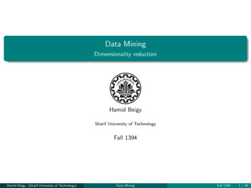
U-10 CONTRIBUTIONS TO THE HYDROLOGY OF THE UNITED STATESHeat-diffusion cells require calibration for different soils and densities, but Shaw and Baver (C, 1939b) noted that salt concentrationsfrom 100 to 10,000 ppm did not affect the readings. None of the typesof cells can be easily installed at depths of more than 5 feet or inundisturbed soil. These cells have not received widespread use andare not presently available from commercial sources.ABSORPTIONLivingston and Koketsu (D, 1920) developed porour points orblocks that would absorb moisture from the adjacent area wheninstalled in the soil. The soil moisture was then estimated from thechange in weight of the points or blocks. Wilson (D, 1927) andStoeckeler (D, 1937) did additional work on the use of absorptionblocks. Davis and Slater (D, 1942) used an absorption block consisting of a porous chamber that contained a close-fitting plug that couldbe removed for weighing. The plug overcame the disac? vantage ofhaving to disturb the installations in the soil each time the blocks wereto be weighed. Dimbleby (D, 1954) developed a pencil-type absorption block which is stuck into the soil; the moisture contents are estimated from the color changes of the "pencil."This method is more qualitative than quantitative and has considerable inherent error; it has never been used extensively.TENSIOMETRICA tensiometer consists of a porous point or cup (usually ceramic)connected through a tube to a pressure-measuring device. The systemis filled with water and the water in the point or cup comes intoequilibrium with the moisture in the surrounding soil, " ater flowsout of the point as the soil dries and creates greater tens'on, or backinto the point as the soil becomes wetter and has less tension. Thesechanges in pressure, or tension, are indicated on a measuring device,usually a Bourdon-tube vacuum gage or a mercury manometer. (Seefig. 6.) The tensiometer may also be attached to a pressure recorder(Richards and Gardner, E, 1936) or to an electonic pressure transducer to maintain a continuous record of tension changes Tensiometers are available in lengths of 6 inches to 4 feet, but probably couldbe manufactured in longer lengths if desired. Specially constructedtensiometers have been installed to depths of 15 feet (Kiel vrds, L. A.,E, 1942). Multiple tensiometers, for determining tension data atseveral depths by use of a single probe, were developed by L. A. Richards (E, 1954).'Tensiometers were probably most fully developed by L. A. Richards(E, 1942). They are most useful for measuring moisture content
METHODS OF MEASURING SOIL MOISTURE IN THE FIELDFIGURE 6. Tensiometers.U-llTop, vacuum-gage type. Bottom, mercury-manometer type.of tensions below approximately 0.9 atmosphere. Such tensions will,on the average, correspond to a range in moisture content fromslightly below field capacity to saturation. At the higher tensionsfound in drier soils, tensiometers become inoperative because airenters the system through the porous point. To determine the moisture content with a tensiometer, the relation between moisture tensionand moisture content must be known. This relation may be found inthe laboratory from a moisture-tension curve constructed by meansof a pressure-membrane or porous-plate apparatus or by collectingsoil samples in the area surrounding a tensiometer installation andrelating the moisture content of the samples to the tensiometer readingobtained concurrently. L. A. Richards (E, 1949) noted that thevacuum-gage type of instrument will generally provide an accuracywithin 2 percent, and the mercury-manometer type is even moreaccurate.Tensiometers are affected by temperature. The temperaturegradients between the porous point of the tensiometer and the soilmay cause variations in the tension readings.The salt concentration in the soil or in the pore water seems to affecttensiometric methods less than electrical methods. S. J. Richards(E, 1938) pointed out that tensiometers exhibit considerable hysteresis effect; they tend to give a higher soil-moisture tension duringsoil drying than during soil wetting. In 1949, L. A. Richards notedthat this effect is not too serious a disadvantage because the wettingcycle is usually rather short in comparison with the drying cycle.Ewart and Baver (B, 1950) reported a serious disadvantage becauseof the timelag in response to soil-moisture changes. Tensiometershave exhibited lags of half an hour to many hours in indicatingchanges in tension caused by changes in moisture content. Recent
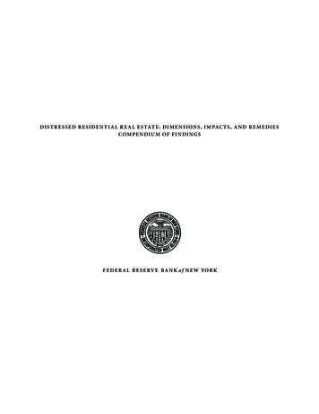
U-12 CONTRIBUTIONS TO THE HYDROLOGY OF THE UNITED STATESstudies by the hydrologic laboratory of the U.S. Geological Survey,Denver, Colo., showed that semipermeable plastic points provide muchfaster response than ceramic points.The tensiometer is probably the easiest to install and the mostrapidly read of all soil-moisture measuring equipment. However,at present, tensiometers are not suitable for installation at depthsgreater than about 20 feet.PENETRATIONMoisture content may be estimated by relating it to the forcerequired to push an instrument through the soil. Allyn and Work(F, 1941a) developed an instrument they called the "availameter" thatmeasured the force required to drive a pair of needles into a soilcore. Allyn (F, 1942) reported a newly developed soil probe withwhich he found moisture-content estimation possible within 0.5 percent. Many others, especially in the Netherlands, have developedequipment for measuring penetration resistance (Hvorslev, F, 1949).Penetration equipment must be calibrated for each type of soil toobtain the relation between penetration resistance and moisture content. The method is very fast, although the equipment is difficultto use in gravelly or stony soils.Penetration equipment designed by the Waterways ExperimentStation, Corps of Engineers, Vicksburg, Miss., consists of a pipe witha point at the bottom and a T-handle containing a pressure-indicatingdevice at the top. Depth of penetration is limited by the amount offorce available.RADIOACTIVEBelcher, Cuykendall, and Sack (G, 1950) apparently introducedthe radioactive method of measuring soil moisture in 1950. Thismethod is based on the principle of measuring the slowing of neutronsemitted into .the soil from a fast-neutron source. The energy loss ismuch greater in neutron collisions with atoms of low atomic weightand is proportional to the number of such atoms present in the soil.The effect of such collisions is to change a fast neutron to a slow neutron. Hydrogen, which is the principal element of low atomic weightfound in the soil, is largely contained in the molecules of the waterin the soil. The number of slow neutrons detected by a countertube after emission of fast neutrons from a radioactive source tubeis electronically indicated on a sealer.The radioactive method indicates the amount of water per unitvolume of soil. The dry density of the soil must be determined ifmoisture content in percent by weight is desired. The U.S. Corpsof Engineers (G, 1955b) stated that the soil volume measured by this
METHODS OF MEASURING SOIL MOISTURE EST THE FIELDU-13method is bulb shaped and has a radius of 6 to 15 inches, accordingto the moisture content and density of the soil.One type of equipment presently available is shown in figure 7.FIGURE 7. Radioactive soil-moisture meter.It consists of: a portable battery-powered sealer having five glowtube decade counters that can accumulate as much as 99,999 counts,and a spring-wound timer that has a time-counting range of y2 to5 minutes and weighs approximately 35 pounds; and a depth moistureprobe having a 5-millicurie fast-neutron source of radium 226 andfinely ground beryllium (half-life, 1,620 years) within a probe 15inches in length and iy2 inches in diameter and having a weight of45 pounds when complete with a lead and paraffin shield 6 inchesin diameter and 8 inches long. These meters have been used withas much as 200 feet of cable.Most investigators have reported an accuracy within 1 to 2 percentby volume. However, to obtain this accuracy, it is recommendedthat the probe be calibrated in the type of soil to be tested and thetype of casing into which the probe is to be lowered.Salt concentration in the soil moisture does not materially affectthe data obtained by the radioactive method. Temperature usuallyhas been considered ineffective in the radioactive method, but there
U-14 CONTRIBUTIONS TO THE HYDROLOGY OF THE UNITED STATESis some evidence of a temperature effect. Readings close to the surface are affected by the position of the probe with respect to the airsoil interface; proximity of the interface causes lower counts thanare characteristic for a particular moisture content at greater depth.Timing errors may be kept to a minimum by using a standard-counttiming cycle of 2 minutes. Access tubes must be kept free of excessmoisture, or erroneous readings will result. One must rememberthat the type and size of casing and the method of installation of theaccess tubes have a considerable effect on the readings, and newcalibration curves should be obtained for each type of installation.Calibration may be done by means of gravimetric sampling in thearea surrounding an access tube, by using large samples in the laboratory, and by use of boric-acid solutions of various concentrations.There is some radioactive hazard from use of this equipment. Thedanger from exposure is proportional to the distance between thesource and the operator and to the length of time of exposure. Thus,most of the danger can be minimized by proper handling of theequipment.The radioactive method is time consuming, especially if the timerequired for calibration is considered. The equipment is heavy anddelicate and equipment failures are likely. Considerable time islost in repairs and in the recalibration needed after most repairs.The repair of the sealer may require the services of an electronicsspecialist.SUMMARYOf the methods described, only the gravimetric, electrical-resistance,tensiometric, and radioactive methods are used commonly. Allmethods have their disadvantages, as well as advantages, and the idealmethod that will give accurate, reliable, and rapid measurements inplace has yet to be developed.The gravimetric method is considered the best for most soilmoisture-measurement problems requiring one-time moisture-contentdata. Because the gravimetric method provides data directly, theeffort and possibility of error associated with the conversion of indirect readings (electrical-resistance, radioactive, and tensiometric)to moisture content are avoided. The gravimetric method requiresless experience than the indirect methods, but also requires more effortunder many conditions. Considerable gravimetric sampling is required for calibration even if one of the indirect methods is used.Some indirect method may have to be used if continuous or frequentmoisture-content readings are necessary.Radioactive methods are probably the best for obtaining repeatedmeasurements of soil moisture in the field. Because of the delicate
METHODS OF MEASURING SOIL MOISTURE IN THE FIELDU-15equipment and the work of calibration, this method requires sufficienteffort and expense that one must consider seriously whether gravimetric sampling would not be a satisfactory substitute.SELECTED REFERENCESA. GBAVTMETBIC METHODSBethlahmy, Nedavia, 1952, A method for approximating the water content ofsoils : Am. Geophys. Union Trans., v. 33, pt. 1, p. 699-706.Bidwell, G. L., and Sterling, W. F., 1925, Preliminary notes on the direct determination of moisture: Assoc. Official Agr. Chemists Jour., v. 8, p. 295-301.Broatlfoot, W. M., 1954a, Core vs. bulk samples in soil-moisture tension aralysis:U.S. Dept. Agriculture, Southern Forest Expt. Sta. Occasional Par r 135,p. 22-25.1954b, Procedures and equipment for determining soil bulk dens
methods for measurement of soil moisture and describes the equipment needed for each method. The advantages and disadvantages of each method are discussed and an extensive list of references is provided for those desiring to study the subject in more detail. The gravimetric metho