Transcription
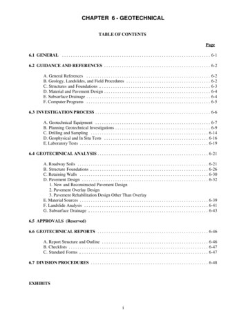
CHAPTER 6 - GEOTECHNICALTABLE OF CONTENTSPage6.1 GENERAL . . . . . . . . . . . . . . . . . . . . . . . . . . . . . . . . . . . . . . . . . . . . . . . . . . . . . . . . . . . . . . . . . . . 6-16.2 GUIDANCE AND REFERENCES . . . . . . . . . . . . . . . . . . . . . . . . . . . . . . . . . . . . . . . . . . . . . . . . 6-2A. General References . . . . . . . . . . . . . . . . . . . . . . . . . . . . . . . . . . . . . . . . . . . . . . . . . . . . . . . .B. Geology, Landslides, and Field Procedures . . . . . . . . . . . . . . . . . . . . . . . . . . . . . . . . . . . . . .C. Structures and Foundations . . . . . . . . . . . . . . . . . . . . . . . . . . . . . . . . . . . . . . . . . . . . . . . . . .D. Material and Pavement Design . . . . . . . . . . . . . . . . . . . . . . . . . . . . . . . . . . . . . . . . . . . . . . . .E. Subsurface Drainage . . . . . . . . . . . . . . . . . . . . . . . . . . . . . . . . . . . . . . . . . . . . . . . . . . . . . . . .F. Computer Programs . . . . . . . . . . . . . . . . . . . . . . . . . . . . . . . . . . . . . . . . . . . . . . . . . . . . . . . .6-26-26-36-46-46-56.3 INVESTIGATION PROCESS . . . . . . . . . . . . . . . . . . . . . . . . . . . . . . . . . . . . . . . . . . . . . . . . . . . . 6-6A. Geotechnical Equipment . . . . . . . . . . . . . . . . . . . . . . . . . . . . . . . . . . . . . . . . . . . . . . . . . . . . 6-7B. Planning Geotechnical Investigations . . . . . . . . . . . . . . . . . . . . . . . . . . . . . . . . . . . . . . . . . . . 6-9C. Drilling and Sampling . . . . . . . . . . . . . . . . . . . . . . . . . . . . . . . . . . . . . . . . . . . . . . . . . . . . . 6-14D. Geophysical and In Situ Tests . . . . . . . . . . . . . . . . . . . . . . . . . . . . . . . . . . . . . . . . . . . . . . . 6-16E. Laboratory Tests . . . . . . . . . . . . . . . . . . . . . . . . . . . . . . . . . . . . . . . . . . . . . . . . . . . . . . . . . . 6-196.4 GEOTECHNICAL ANALYSIS . . . . . . . . . . . . . . . . . . . . . . . . . . . . . . . . . . . . . . . . . . . . . . . . . . 6-21A. Roadway Soils . . . . . . . . . . . . . . . . . . . . . . . . . . . . . . . . . . . . . . . . . . . . . . . . . . . . . . . . . . .B. Structure Foundations . . . . . . . . . . . . . . . . . . . . . . . . . . . . . . . . . . . . . . . . . . . . . . . . . . . . .C. Retaining Walls . . . . . . . . . . . . . . . . . . . . . . . . . . . . . . . . . . . . . . . . . . . . . . . . . . . . . . . . . .D. Pavement Design . . . . . . . . . . . . . . . . . . . . . . . . . . . . . . . . . . . . . . . . . . . . . . . . . . . . . . . . .1. New and Reconstructed Pavement Design2. Pavement Overlay Design3. Pavement Rehabilitation Design Other Than OverlayE. Material Sources . . . . . . . . . . . . . . . . . . . . . . . . . . . . . . . . . . . . . . . . . . . . . . . . . . . . . . . . . .F. Landslide Analysis . . . . . . . . . . . . . . . . . . . . . . . . . . . . . . . . . . . . . . . . . . . . . . . . . . . . . . . .G. Subsurface Drainage . . . . . . . . . . . . . . . . . . . . . . . . . . . . . . . . . . . . . . . . . . . . . . . . . . . . . .6-216-266-306-326-396-416-436.5 APPROVALS (Reserved)6.6 GEOTECHNICAL REPORTS . . . . . . . . . . . . . . . . . . . . . . . . . . . . . . . . . . . . . . . . . . . . . . . . . . 6-46A. Report Structure and Outline . . . . . . . . . . . . . . . . . . . . . . . . . . . . . . . . . . . . . . . . . . . . . . . . 6-46B. Checklists . . . . . . . . . . . . . . . . . . . . . . . . . . . . . . . . . . . . . . . . . . . . . . . . . . . . . . . . . . . . . . . 6-47C. Standard Forms . . . . . . . . . . . . . . . . . . . . . . . . . . . . . . . . . . . . . . . . . . . . . . . . . . . . . . . . . . 6-476.7 DIVISION PROCEDURES . . . . . . . . . . . . . . . . . . . . . . . . . . . . . . . . . . . . . . . . . . . . . . . . . . . . . 6-48EXHIBITSi
LIST OF TABLESTablesPage6-1 General Investigation Equipment Requirements . . . . . . . . . . . . . . . . . . . . . . . . . . . . . . . . . . . . . 6-96-2 Sources of Regional Geotechnical Information . . . . . . . . . . . . . . . . . . . . . . . . . . . . . . . . . . . . . 6-116-3 Use of Trenching and Test Pits . . . . . . . . . . . . . . . . . . . . . . . . . . . . . . . . . . . . . . . . . . . . . . . . . 6-126-4 Guidelines for Geotechnical Drilling Investigations . . . . . . . . . . . . . . . . . . . . . . . . . . . . . . . . . 6-136-5 Test Borings - Types and Application . . . . . . . . . . . . . . . . . . . . . . . . . . . . . . . . . . . . . . . . . . . . 6-146-6 Sampling Guidelines . . . . . . . . . . . . . . . . . . . . . . . . . . . . . . . . . . . . . . . . . . . . . . . . . . . . . . . . . 6-156-7 Guidelines for Using Geophysical Methods . . . . . . . . . . . . . . . . . . . . . . . . . . . . . . . . . . . . . . . 6-176-8 Common Procedural Errors using Standard Penetration Test . . . . . . . . . . . . . . . . . . . . . . . . . . 6-176-9 Empirical Values, Relative Density, & Unit Weights of Granular Soils . . . . . . . . . . . . . . . . . . 6-186-10 Guideline for Selection of Laboratory Tests . . . . . . . . . . . . . . . . . . . . . . . . . . . . . . . . . . . . . . . 6-206-11 Roadway Soils Analysis Factors . . . . . . . . . . . . . . . . . . . . . . . . . . . . . . . . . . . . . . . . . . . . . . . . 6-236-12 Shrink/Swell Factors for Common Materials (2) . . . . . . . . . . . . . . . . . . . . . . . . . . . . . . . . . . . 6-246-13 Preliminary Foundation Type Selection . . . . . . . . . . . . . . . . . . . . . . . . . . . . . . . . . . . . . . . . . . 6-296-14 Soil Support Correlations . . . . . . . . . . . . . . . . . . . . . . . . . . . . . . . . . . . . . . . . . . . . . . . . . . . . . 6-346-15 Regional Factor Guidelines for Pavement . . . . . . . . . . . . . . . . . . . . . . . . . . . . . . . . . . . . . . . . 6-36ii
CHAPTER 6 - GEOTECHNICAL6.1 GENERALThis chapter provides guidance for all geotechnical investigations, analyses, and reports produced by theFederal Lands Highway Divisions. Although greatly advanced in recent years, the state-of-the-art of thegeotechnical engineering field is still largely dependent upon engineering judgment to provide the mostefficient and economical investigations. Dealing with the variability of projects, terrains, climates, and clientagency constraints requires flexibility and resourcefulness.Although primarily intended for use by a geotechnical engineer/geologist, the information contained hereincan be used by designers and others during the design process. Geotechnical responsibilities includeconducting investigations, performing analyses, and providing recommendations for the following:Geological and geotechnical reconnaissance.Roadway soils.Cut and fill slopes.Foundations.Landslides.Material sources.Retaining walls.Subsurface drainage.Pavements.Each of these areas are addressed individually, providing guidelines, direction, and references for more specificand detailed information.6-1
6.2 GUIDANCE AND REFERENCESThe publications listed in this section provided much of the fundamental source information used in thedevelopment of this chapter. While this list is not all inclusive, the publications listed will provide additionalinformation to supplement this manual.A. General References.Bowles. Foundation Analysis and Design. 4th ed. McGraw-Hill Book Company. 1988.Peck, Hanson, and Thornburn. Foundation Engineering. John Wiley and Sons, Inc. 1974.Terzaghi and Peck. Soil Mechanics in Engineering Practice. John Wiley and Sons, Inc. 1967.Wintercorn. Foundation Engineering Handbook. 2nd ed. Van Nostrand Reinhold Company. 1991.Canadian Foundation Engineering Manual. 3rd ed. Canadian Geotechnical Society. 1992.Geotechnical Engineering Notebook. DOT, FHWA. Office of Engineering, Bridge Division.Geotextile Engineering Manual. DOT, FHWA. 1984.Soil Dynamics, Deep Stabilization, and Special Geotechnical Construction. NAVFACDesign Manual 7.3. Department of the Navy. April 1983.Soil Mechanics. NAVFAC Design Manual 7.1. Department of the Navy. September 1986.B. Geology, Landslides, and Field Procedures.Acker. Basic Procedures for Soil Sampling and Core Drilling. Acker Drill Co., Inc. 1974.Beck. Physical Principles of Exploration Methods. New York. John Wiley and Sons, Inc. 1982.Hamblin and Howard. Physical Geology Laboratory Manual. Minneapolis. Burgess Publishing Co. 1975.Hunt. Geotechnical Engineering Investigation Manual. New York. McGraw-Hill Book Co. 1984.Pitts. A Manual of Geology for Civil Engineers. Salt Lake City. John Wiley and Sons, Inc. 1984.Manual on Subsurface Investigations. AASHTO. 1988.Driller's Safety Manual. U.S. Department of the Interior, Bureau of Reclamation. 1973.Geotechnical Instrumentation (FHWA Workshop Manual). DOT, FHWA.The Cone Penetrometer Test. FHWA-SA-91-043. DOT, FHWA. 1992.The Flat Dilatometer Test. FHWA-SA-91-044M. DOT, FHWA. 1992.Advanced Technology for Soil Slope Stability, FHWA-SA-94-005. DOT, FHWA. 19946-2
6.2 Guidance and References. (continued)Handbook of Engineering Geophysics (Volume 1, Seismic, 1984 and Volume 2,Electrical Resistivity, 1980). Minneapolis. Bison Instruments, Inc.The Pressuremeter Test for Highway Application. FHWA-IP-89-008. DOT, FHWA. 1989.Landslides Investigation and Mitigation. Transportation Research Board, National Academy of Sciences.Washington, DC. 1995.Rock Slopes: Design, Excavation, Stabilization. FHWA-TS-89-045. DOT, FHWA. 1989.Rock Blasting and Overbreak Control. FHWA-HI-92-001. DOT, FHWA. 1991.Duncliff. Geotechnical Instrumentation for Monitoring Field Performance. John Wiley & Sons, Inc. 1988.C. Structures and Foundations.Poulos and Davis. Pile Foundation Analysis and Design. 1980.Drilled Shafts: Construction Procedures and Design Methods. DOT, FHWA. 1988.Handbook on Design of Piles and Drilled Shafts Under Lateral Load. FHWA-IP-84-011, DOT, FHWA.1984.Behavior of Piles and Pile Groups Under Lateral Load. FHWA-RD-85-106. DOT, FHWA. 1986.AASHTO LFRD Bridge Design Specifications. AASHTO. 1994.Reeves. Applications of Walls to Landslide Control Problems. American Society of Civil Engineers. 1982.Spread Footings for Highway Bridges. FHWA-RD-86-185. DOT, FHWA. 1987.Manual on Foundation Investigation. AASHTO. 1978.AASHTO-AGC-ARTBA Taskforce Report. In Situ Improvement Techniques. 1990.Foundation and Earth Structures. Design Manual 7.2; NAVFAC DM-7.2. Department of the Navy. 1982.Permanent Ground Anchors. FHWA-DP-68-1R. DOT, FHWA. 1984Manual on Design and Construction of Driven Pile Foundations. FHWA DP-66-1. DOT, FHWA. Officeof Engineering, Bridge Division. 1986.Retaining Wall Design Guide. Second Edition (FHWA-FLP-94-006). U.S. Department of Agriculture, ForestService. September 1994.Soils and Foundation Workshop Manual. DOT, FHWA. Office of Engineering, Bridge Division. 1993.6-3
6.2 Guidance and References. (continued)D. Material and Pavement Design.Techniques for Pavement Rehabilitation, A Training Course. 3rd Revision, ERES Consultants, Inc. 1987Pavement Design Principles and Practices, A Training Course. ERES Consultants, Inc. 1987Krebs and Walker. Highway Materials. McGraw-Hill Book Company. 1971.Yoder and Witczak. Principles of Pavement Design. 2nd ed. John Wiley and Sons, Inc. 1975.AASHTO Pavement Overlay Design. FHWA-HI-94-048. DOT, FHWA. 1994Distress Identification Manual for the Long-Term Pavement Performance Projects. SHRP-P-338, SHRP.1993Guide for Design of Pavement Structures. AASHTO. 1993.Pavement Rehabilitation Manual. DOT, FHWA. Office of Engineering, Pavement Division. 1990.Soils Manual for the Design of Asphalt Pavement Structures. The Asphalt Institute. 1986Thickness Design - Asphalt Pavements for Highways and Streets. The Asphalt Institute. 1991.Pavement Notebook for FHWA Engineers. Office of Engineering, Pavment Division.E.Subsurface Drainage.Geotextile Design and Construction Guidelines. FHWA-HI-95-038. DOT, FHWA. 1995.Drainage of Asphalt Pavement Structures. The Asphalt Institute Manual Series No. 15. September 1984edition.Geocomposite Drains. Report No. FHWA/RD-86/171. DOT, FHWA. October 1986.Geotechnical Fabrics. Report No. FHWA/RD-80/021. DOT, FHWA. 1980.Highway Subdrainage Design. Report No. FHWA-TS-80-224. DOT, FHWA. 1980.Improving Subdrainage and Shoulders of Existing Pavements. Report No. FHWA/RD-81/078. DOT, FHWA.January 1982.Underground Disposal of Storm Water Runoff.February 1980.Report No. FHWA-TS-80-218.6-4DOT, FHWA.
6.2 Guidance and References. (continued)F. Computer Programs. The following is a listing of computer programs that are available and may be usedwhen appropriate:FoundationsGRL WEAP 1.994-1 - Wave Equation Analysis of PilesNAVPILE - Nevada Pile Analysis (Static)COM 624 P Version 2 - Lateral Load Analysis of Driven and Non-Driven PilesSPILE - Ultimate Static Capacity for Driven PilesCBEAR - Bearing Capacity Analysis for Shallow FoundationsPavment DesignDARWin - Pavement Design Analysis and Rehabilitation for WindowsDAMA - Pavment Structural Analysis Using Multi-Layer Elastic TheorySlope StabilityLEASE I - Limiting Equilibrium Analysis in Soil EngineeringSTABL4 - Slope Stability AnalysisSLOPIN - Calcomp Plot of Inclinometer DataINCLIN - Print Plot of Inclinometer DataXSTABL - Slope Stability AnalysisDIGIPRO - Data Reduction and Graphing Software for InclinometersEMBANK - One Dimensional Consolidation due to Embankment LoadsGeophysical ProgramsSEISMIC12 - Channel Refraction Seismic Test Data AnalysisRESIST - Resistivity Data AnalysisSEISREFA - Sesimic Refraction Analysis6-5
6.3 INVESTIGATION PROCESSThe primary purpose of a geotechnical investigation is to provide design engineers with a knowledge of thesubsurface conditions at a specific project site. The investigation should also provide the construction projectengineers and contractors with information concerning the materials and conditions that may be encounteredin the field.The scope and cost of a geotechnical investigation should be adjusted to the size and complexity of theproposed project. The potential for catastrophic failure and/or failure consequences must be evaluated whenestablishing scope of the investigation.In all geotechnical investigations, safety of field crew and traveling public must be of high priority. The natureof the equipment used and climatic conditions often present potential hazards that must be evaluated on anindividual basis. It is the responsibility of the geotechnical engineer/ geologist, as well as field crew membersto adjust the investigation program and/or provide equipment, training, and other means to provide safeworking conditions. Field crews should be aware of and use traffic safety control plans based upon MUTCDrequirements.Geotechnical investigations should not be attempted until certain project-specific information has beenobtained. The following list identifies typical project requirements and suggests where the necessaryinformation on specific subjects may be obtained. Exhibit 6.1 is used to gather and document this preliminaryinformation.Possible Sources for Site Specific InformationProject SpecificsInformation SourcesType of proposed project.Proposed project termini.Funds available.Schedule requirements.Planning and Coordination orItems requiring investigation.Project Development UnitLocal authorities to contact.Location and type of utilities present.Scope of investigation desired.Geotechnical EngineerAvailability of equipment.Location of structures.Structures/Bridge UnitSite maps and field reference systems.Location and/or Survey UnitSpecific site restrictions such aswater quality, environmental considerations,or client agency considerations.Right-of-entry (access) restrictions.Environmental UnitApplicable property owners6-6
6.3 Investigation Process. (continued)Special situations occasionally require in situ testing or instrumentation to obtain accurate information for bothdesign and construction. These tests and instrumentation may be highly specialized and may requirespecialized assistance. The following are typical reasons for specialized instrumentation:Construction control, both during design and/or construction.Safety.Verifying design assumptions.Verifying new construction techniques.Verifying long-term satisfactory performance.Verifying contractor compliance with specifications.Advancing the state-of-the-art.Legal reasons.A. Geotechnical Equipment. Sometimes to perform geotechnical investigations, specialized subsurfaceinvestigation equipment is required. In cases of sporadic use or when highly trained technicians must beassigned exclusively to operate equipment, the geotechnical unit may prefer to use consultants and/orcontractors to provide such services in lieu of actually purchasing and maintaining such equipment. Beloware typical sources for technical assistance to obtain equipment or expertise:Other FLH Offices.FHWA Research and Implementation units.Local government agencies.Other Federal Government agencies.Universities.Private consultant.Equipment manufacturers.Each geotechnical unit should maintain access to the latest equipment and technology so it can performefficient and effective investigations. This policy also provides FHWA the opportunity to implement andexperiment with new technology, equipment and ideas. Equipment can be grouped into three major categories:1.2.3.Drill equipment and sampling toolsGeophysical and in situ testing equipmentPavement evaluation equipment.In addition to these major areas, incidental hand tools are required for the generalized reconnaissance type ofinvestigations usually performed by an engineer or geologist. This equipment consists of (as a minimum), aBrunton compass, survey transit, cloth tape, hand level, rock hammer, hand augers, test pit excavationequipment, and record keeping notebooks.Minimum drill equipment should consist of a power auger drill rig capable of advancing an 200 millimeterhollow stem auger 35 meters in very stiff clays or dense sand and gravel. The drill should be capable oftraversing soft ground, moderately steep slopes, and rough terrain. The drill should also have capabilities forobtaining at least 45 meters of "N" size or larger rock cores. Soil testing and sampling capabilities shouldconsist of at least the "Standard Penetration Test AASHTO T 206" and the "Thin Walled Tube SampleAASHTO T 207". In addition to the large drilling equipment, a portable drill capable of drilling at least "B"size core a minimum of 15 meters, is desirable. Geotechnical Engineering Investigation Manual, by Hunt,provides an excellent source of detailed information on investigation equipment requirements.6-7
6.3 Investigation Process. (continued)The geophysical equipment should consist of a portable, single channel seismic unit and a resistivity unit. Inaddition, a multi-channel seismic unit with enhancement capability is desirable. Physical Principles ofExploration Methods, by Beck, and manufacturer's literature provide the best source of geophysical equipmentinformation.Minimum in-situ test equipment should include a cone penetrometer, a vane shear, and in-place densityequipment (sand cone, nuclear gauge, etc.). Project site instrumentation such as inclinometer, piezometer, andstrain gage readout devices should also be available. A detailed instrumentation equipment listing is availablein the Geotechnical Instrumentation for Monitoring Field Performance, by Dunncliff.Available pavement evaluation equipment should consist of a calibrated distance measuring device, pavementdeflection equipment, roughness measurement, and pavement core drill. In addition, access and familiaritywith skid testing devices, photo logging and video tape equipment is desirable.6-8
6.3 Investigation Process. (continued)Table 6-1 provides guidelines for the type of equipment and the frequency of use that is typical for differenttypes of geotechnical investigations.Table 6-1General Investigation Equipment RequirementsUse by Equipment TypeType ionWaterSupplyEquipmentIn situStrengthDevicesIn situMonitorsBackhoeRoadway Soils1442334341Foundations1122242224Existing PavementEvaluations4214411444Material 342322Use Code:1 Frequently2 Occasional3 Seldom4 Usually InappropriateB. Planning Geotechnical Investigations. After the project has been initiated, the first phase of anygeotechnical investigation should consist of a desk review of available geotechnical information and projectspecific requirements and information. This information is vital to planning an efficient, cost-effective fieldinvestigation. The information is used to do the following:Determine the nature and scope of the geotechnical field investigation.Select proper field equipment.Estimate manpower, time, and total costs.Select field reference system for geotechnical reports.Determine site conditions that may restrict or limit the investigation.The wide range of geographical areas where projects may be located requires access to geotechnicalinformation from a variety of sources. Table 6-2 provides an initial listing of potential sources and a briefdescription of information available. Each geotechnical unit should supplement the sources listed in Table 6-2by establishing and maintaining a file of commonly used regional information.6-9
6.3 Investigation Process. (continued)In addition, the following should be available from the local and/or in-house resource center:Aerial photographs.Previous geotechnical reports.Survey notes.As-built plans.After this information is obtained and studied, a preliminary boring plan should be developed. This boringplan should contain information on the following:Type, number, and location of proposed test holes.Estimated depth, type of testing, and sampling interval for each hole.Type and location of utilities.List of local contacts for right-of-access and for utilities.Arrangements for traffic control (flagmen, signing, etc.).Source of drilling water.Instructions for communications, sample handling.6 - 10
6.3 Investigation Process. (continued)Table 6-2Sources of Regional Geotechnical InformationSource: U.S. Geological Survey (USGS). Consult USGS Index of Publications. Index from Superintendent ofDocuments, U.S. Government Printing Office, Washington, D.C. 20402. Maps available from U.S. Departmentof Interior, Geological Survey, National Center, 12201 Sunrise Valley Drive, Reston, VA 22092. Geological index mapsIndividual maps of each State showing coverage and sources of all published geological maps.Geological Quadrangle Maps of United StatesThis series supplants the older geological folios including areal or bedrock geology maps with briefdescriptive text. Series is being extended to cover areas not previously investigated.Bulletins, professional papers, circulars, annual reports, monographsGeneral physical geology emphasizing all aspects of earth sciences, including mineral and petroleumresources, hydrology and seismicity. Areal and bedrock geology maps for specific locations included inmany publications.Water supply papersSeries includes papers on groundwater resources in specific localities and are generally accompanied bydescription of subsurface conditions affecting groundwater plus observations of groundwater levels.Topographic mapsTopographic contour maps in all States, widespread coverage being continually expanded.Source: Geological Society of America. Consult societies publications. Index available from GeologicalSociety of America, P.O. Box 9140, 3300 Penrose Place, Boulder, Colorado 80302. Monthly bulletins, special papers, and memoirsTexts cover specialized geological subjects and intensive investigations of local geology. Detailedgeology maps are frequently included in the individual articles.Geological mapsPublications include general geological maps of North and South America, maps of glacial deposits, andPleistocene aeolian deposits.Source: U.S. Department of Agriculture (USDA) Soil Conservation Service. Consult List of Published SoilSurveys (published annually). Available from USDA, Soil Conservation Service, Washington, D.C. Soil maps and reportsSurveys of surface soils described in agriculture terms. Physical geology summarized. Excellent forhighway or airfield investigations. Coverage mainly in Midwestern, Eastern, and Southern United States,Source: State Geological Surveys/Sate Geologist Offices. Most States provide excellent detailed localgeological maps and reports covering specific areas or features in the publications of the State geologist. Someoffices are excellent sources of information on foreign countries.Tables 6-3 and 6-4 may be used as guidelines for development of the investigation plan. An on-site visit isdesirable and often required as part of the development of a detailed investigation plan before field crews beginwork at the project site.6 - 11
6.3 Investigation Process. (continued)Table 6-3Use of Trenching and Test PitsExplorationMethodGeneral UseCapabilitiesLimitationsHandExcavatedTest Pitsand ShaftsBulk sampling, in-situ testing,visual inspection.Provides data in inaccessibleareas, less mechanicaldisturbance of surroundingground.Expensive, timeconsuming, limited todepths abovegroundwater level.BackhoeExcavatedTest Pitsand TrenchesBulk sampling in-situ testing,visual inspection, excavationrates, depth of bedrock andgroundwater.Fast, economical, generallyless than 3 meters deep, canbe up to 6 meters deep.Equipment access,generally limited todepths abovegroundwater level,limited undisturbedsampling.DrilledShaftsPre-excavation for piles andshafts, landslide investigations,and drainage wells.Fast, more economical thanhand excavated, minimum750 mm diameter maximum2 meters diameterEquipment access,difficult to obtainundisturbed samplescasing may obscurevisual inspection, andcostly mobilization.Dozer CutsBedrock characteristics, depth ofbedrock and groundwater level,rippability, increase depthcapability of backhoes, level areafor other exploration equipment.Relatively low cost,exposures for geologicmapping.Exploration limited todepth abovegroundwater level.6 - 12
6.3 Investigation Process. (continued)Table 6-4Guidelines for Geotechnical Drilling Investigations**Information obtained from drilling may be supplemented by geophysical investigations.Type of Investigation/Number of BoringsDepth of BoringsStructure Foundations:Minimum one boring per substructure unit.Continue borings:(1) through unsuitable foundation soils (such as peats,highly organic soils, soft fine-grained soils, loose coarsegrained soils, etc.) into competent material of suitablebearing capacity and;(2) to depth where added stress due to estimated footingload is less than 10 percent of the existing effective soiloverburden stress or;(3) minimum of 3 meters into bedrock if bedrock isencountered at shallower depth as determined by (2).Retaining Walls:Minimum 1 boring per wall. Additional borings spaced15 to 60 meters. Some borings should be in front of andin back of wall.Continue borings to depth of 2 times wall height orminimum of 3 meters into bedrock.Bridge Approach Embankments Over Soft Ground:When approach embankments are placed over softground at least one boring should be made at eachembankment to determine the problems associated withstability and settlement of the embankment. Test boringsat proposed abutment locations may serve both stabilityand structural investigations.Same as established above for structure foundations:Cuts and Embankments:Space borings every 60 meters (erratic conditions ) to150 meters (uniform conditions) with at least one boringtaken in each separate land form.Cuts1) In stable materials extend borings minimum 3 metersbelow proposed centerline grade.2) In weak soils, at or near proposed centerline grade,extend borings below grade to competent materials.EmbankmentsContinue borings to competent material or to depth oftwice the embankment height.For high cuts and fills (8 meters or greater), it isdesirable to have a minimum two borings along a straightline to establish geological cross section for analysis.Additional shallow explorations (hand auger holes) takenat approach embankment locations are an economicalway to determine depth of unsuitable surface soils ortopsoil.Landslides:Minimum 2 borings along a straight line to establishgeologic cross section for analysis. Number of sectionsdepends on extend of stability problem. For an activeslide, place at least one boring above and below slidingarea.Extend borings to an elevation below active or potentialfailure surface and into competent stratum, or to a depthfor which failure is unlikely because of geometry ofcross section.Material Sites (Borrow Sources and Quarries)Space borings or test pits on a grid pattern every 30 to45 meters or change of material.Extend exploration to base of deposit or to depthrequired to provide needed quantity.Pavement RehabilitationMinimum one boring or test pit per kilometer withadditional exploration as needed to define changes insubgrade material, pavement section, and locallydistressed areas.Extend depth to at least 0.6 meters below expected subgrade.Bore holes used to install inclinometers must beextended to competent material below the slidemovement.6 - 13
6.3 Investigation Process. (continued)C. Drilling and Sampling. The purpose of a drilling and sampling program is to obtain samples that reasonablyrepresent subsurface conditions over the entire project site. Guidance for selection of the applicable test boring type canbe found in Table 6-5.Sampling type and frequency is dependent upon both the type of material encountered and the purpose of theinvestigation. The AASHTO Manual on Subsurface Investigation provides additional detailed information. Whenappropriate, continuous sampling provides the most complete and accurate information. When equipment, materials,or cost effectiveness prevent continuous sampling, typical sampling frequencies used are provided in
Manual on Design and Construction of Driven Pile Foundations. FHWA DP-66-1. DOT, FHWA. Office of Engineering, Bridge Division. 1986. Retaining Wall Design Guide. Second Edition (FHWA-FLP-94-006). U.S. Department of Agriculture, Forest Service. September 1994. Soils and Foundation Workshop Manual. DOT,
