Transcription
White PaperDATA CENTER CABLINGDESIGN FUNDAMENTALSTelecommunications Cabling Infrastructure Requirementsaccording the Availability Classes I-IV of EN 50600-2-4
IntroductionWith the completion by end of Q1 2016, the new European standardseries (EN 50600-x) covering the design of “Data Centre Facilities andInfrastructures” will be a new a comprehensive European reference forall parties involved in designing, building and operating data centers.Developed by CENELEC, an in dependent, non-profit European standardsorganization, it is commercially neutral and internationally applicable byreferencing ISO/IEC standards.As part of this standard series, the EN 50600-2-4 standard, officiallyreleased in January 2015, covers the “Telecommunication CablingInfrastructure”. It is mainly focusing on design requirements for the differentDC availability classes with strong emphasis on migration and growth.This white paper explains the EN 50600-2-4 in the context of the EN50600-x standard series. Furthermore, the document highlights therequirements for fixed cabling infrastructures, cross-connect cabinets,equipment row cabinets, cable management and pathway systemsaccording the data center availability classes.ContentsThe European Standard Series EN 50600-xIntroduction & Structure. 3Key Advantages. 4Comparison with other Standards/Design Concepts. 5Key Benefits per Target Group. 5EN 50600-1: General Concepts & Availability Classes. 6EN 50600-2-4: Telecommunications Cabling InfrastructureContent and Structure. 7Cabling Types. 8Point-to-Point Cabling. 8Fixed Cabling. 9Availability Classes and resulting Cabling Architectures. 10Cabling Class 1. 11Cabling Class 2. 11Cabling Class 3. 12Cabling Class 4. 12Specifications & Requirements for the Cabling Classes. 13Requirements for Cabinets/Racks/Frames. 15General requirements. 15Requirements for dimensions. 15Recommendations for Cable Management. 15Recommendations for Overhead Cabling. 152
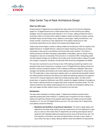
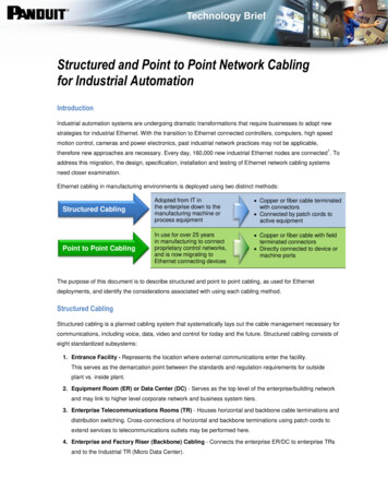
The European Standard Series EN 50600-xIntroduction & StructureThis series of European standards specifies requirements and recommendations to support thevarious parties involved in the design, planning, procurement, integration, installation, operationand maintenance of facilities and infrastructures within data centers. These parties include: Owners, facility managers, ICT managers, project managers, main contractors Consultants, architects, building designers and builders, system and installation designers Suppliers of equipment Installers, maintainersIt has been developed to address European demands regarding DC Design: A European DC design standard was required with European applicable requirements Demand for a universally applicable DC design standard series which adopts a holisticapproach covering all aspects of the design of DC facilities & infrastructures includingmanagement and operational information Support of European Commission’s Code of Conduct on Data Centers Energy Efficiency Existing design schemes were driven by design resilience concepts rather than offering abusiness oriented assessment approach using a design vs. cost perspective The EN 50600-x series covers all design requirements for the entire set of facilities andinfrastructures of a data center in separate standards. The following graphic shows the structureand the relationships between all EN 50600-x standards.EN 50600-2-1BuildingConstructionEN 50600-2-2Power DistributionEN 50600-2-3EnvironmentalControlEN 50600-1General ConceptsEN 50600-2-4TelecommunicationsCablingInfrastructureEN 50600-2-5Security SystemsFigure 1: EN 50600-x Structure3EN 50600-3-1Management& OperationalInformation
Key AdvantagesThe EN 50600-x standard series has been developed by CENELEC (European Committeefor Electrotechnical Standardization), an independent, non-profit European standardizationorganization.EN 50600-x is a European standard series that:Offers independent and comprehensive definitions & requirements for DC design and operation forall facilities & infrastructures Is commercially neutral without inherent assessment system Is internationally applicable for international DC owners/managers/operators by-- Replacing the European normative references with international counter parts-- Replacing European security standards by local counter partsFurthermore, the EN 50600-x: Offers as sole DC design standard an energy efficiency enablement approach that provides abasis for all energy efficiency KPI concepts, available or currently in development Gives guidance about the selection process for the required overall data center designparameters Provides design principles for DC designers and DC owners Defines non-profit oriented certification criteriaIn order to maintain and control the selected design as well as the energy efficiency criteria duringoperation, the supporting EN 50600-3-1 specifies processes for DC management and operations.Additionally, the modularity of the EN 50600 standard series enables the future integration ofadditional standards about management and operation resp. data center KPIs.4
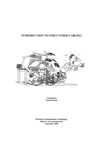
Comparison with other Standards/Design ConceptsThe following graphic has been developed in order to compare EN 50600-x with other standardsin the data center environment including concepts from commercial assessors (for example theUptime Institute, Data Center Alliance or essorsAll DC facilities & InfrastructuresCabling onlyAll DC facilities& InfrastructuresMainly Power &Environmental ControlþýýýEurope/Internationally applicableby using ISO/IEC standards asreferencesUnited StatesUnited StatesInternationalEnergy Efficiency EnablementþýýýManagement & Operationþýý?Inclusion of global KPIs(ISO/IEC 30134-x))þýý?Commercially NeutralþþþýIndependent Assessmentþ(Cabling Only)þ?ýBusiness Approach(design vs cost)þýýþScopeEuropean StandardRegional ApplicationFigure 2: EN 50600-x vs. other design standards/design conceptsKey Benefits per Target GroupThe availability of the EN 50600-x standard series is late in time compared to other standards ordesign concepts covering data centers. Nevertheless, EN 50600-x offers a lot of advantages to allparties involved in designing, building and operating data centers. The key advantages per interestgroup are:The DC Owner/Manager/Operator can use EN 50600-x series to translate business demandsvia risk assessment in terms of infrastructure availability vs. cost in order to: Identify & select appropriate outline design requirements to provide the desired availability Apply concepts which are standards-based, business oriented and product/technology agnosticFor DC Consultants, EN 50600-x series is a normative reference for the assessment of anappropriate DC design including defined design processes and design principles for all datacenter facilities and infrastructures.Architects & engineers get a suite of integrated standards for the design of data center facilities& infrastructures including defined design processes and design principles.5
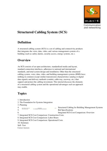
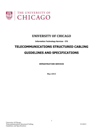
EN 50600-1: General Concepts & Availability ClassesEN 50600-1 describes the general concepts of the standard series and has the following scope:EN 50600-1: Details the issues to be addressed in a business risk and operating cost analysis enablingapplication of an appropriate classification of the data center Defines the common aspects of data centers including terminology, parameters and referencemodels (functional elements and their accommodation) addressing both the size and complexityof their intended purpose Describes general aspects of the facilities and infrastructures required to support effectiveoperation of telecommunications within data centers Specifies a classification system, based upon the key criteria of “availability”, “security” and“energy-efficiency” over the planned lifetime of the data center, for the provision of effectivefacilities and infrastructure Describes the general design principles for data centers upon which the requirements of the EN50600 series are based including symbols, labels, coding in drawings, quality assurance andeducationFurthermore, it functions as a base for all other standards of the series because their infrastructureshave to be designed according to the chosen overall data center availability class, derived fromEN 50600-1.The following graphic shows the main design criteria according to the chosen availability class forthe infrastructures power distribution, environmental control and telecommunications cabling.Availability of overall set of facilities and infrastructuresLowMediumHighVery HighAVAILABILITY CLASSInfrastructurePower supply/distributionEN 50600-2-2Environmental controlEN 506000-2-3TelecommunicationscablingEN 50600-2-41234Single-path(no redundancy ofcomponents)Single-path(resilience providedby redundancy ofcomponents)Multi-path(resilience provided byredundancy of systems)Multi-path(fault tolerant even duringmaintenance)No specific requirementsSingle-path(no redundancy ofcomponents)Single-path(resilience providedby redundancy ofcomponents)Multi-path(resilience provided byredundancy of systems).Allows maintenanceduring operationDirect ConnectionorSingle-path fixedinfrastructureSingle-path using fixedinfrastructure with ENIredundancyMulti-path using fixedinfrastructure with ENIredundancy and diversepathwaysMulti-path using fixedinfrastructure with ENIredundancy, diversepathways and redundantdistribution areasFigure 3: Availability Classes according EN 50600-1The architectural and design requirements of the different availability classes for thetelecommunications cabling infrastructure are subject of the next chapters of this document.6
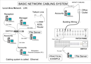
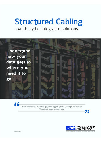
EN 50600-2-4: Telecommunications Cabling InfrastructureContent and StructureThe telecommunications cabling within the data center serves to support the following: Data center information technology and network telecommunications Monitoring and controlling of other data center infrastructures Building management and automationTherefore, EN 50600-2-4 addresses the wide range of telecommunications cabling infrastructureswithin data centers based upon the criteria and classifications for “availability” within EN 50600-1.EN 50600-2-4 specifies requirements and recommendations for the following: Information technology and network telecommunications cabling (e.g. SAN and LAN) General information technology cabling to support the operation of the data center Telecommunications cabling to monitor and control, as appropriate, power distribution,environmental control and physical security of the data center Other building automation cabling Pathways, spaces and enclosures for the telecommunications cabling infrastructuresThe following graphic highlights the topics covered by EN 50600-2-4:EN 50600-2-4Cabling TypesPoint-To-PointFixed CablingCabling architectures and designrequirements according theavailability classes of EN 50600-1Structured cabling for the DCoperation (e.g. NOC)EN 50173-2Structured cabling for the IT functionof the DC (e.g. networking andstorage in the computer room)EN 50173-5Structured cabling for monitoring &control of the building management& security functions of the DCClasses I-IVEN 50173-6Structured application specific cablingRequirements & recommendationsfor pathways and spacesAnnex A: Cabling ConceptsPathways, pathway systems,cable management systems,cabinets/racks/framesFigure 4: Content & Structure of EN 50600-2-4The main focus when developing the EN 50600-2-4 was, in addition to the architectures andrequirements for the availability classes, on migration and growth. The growth of IT capacity andthe migration of applications towards higher speed are very dynamic in data centers. The cablinginfrastructure of a data center has to be able to support these dynamics by enabling quick andeasy extension of the data center (e.g. commissioning of additional equipment) and by offeringmigration paths for the network and storage applications used in the DC.EN 50600-2-4 supports migration and growth by defining appropriate requirements for cablingarchitectures, cross-connects and pathway systems. These requirements will be explained in thefollowing chapters.7
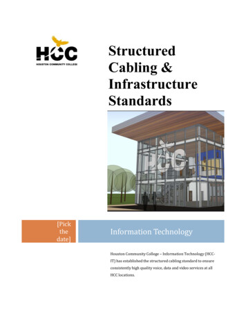
Cabling TypesAlthough EN 50600-2-4 is covering several types of cabling (see figure 4), it does not define anyrequirement for the structured cabling itself. It has not been created to supersede existing Europeancabling standards but it points to those for cabling definitions. The EN 50600-2-4 defines basically2 cabling types:Point-to-point: Direct connection of two pieces of IT equipment using a dedicated cablerather than a generic cabling system. The point-to-point connection methoduses discrete cords (typically factory-produced) that directly connect the activeequipment.Fixed Cabling: Structured cabling including the generic cabling solutions of the EN 50173series between closures which have either peer-to-peer or hierarchical structureand which enables the installation of cross-connects or interconnects at thoseclosures.Point-to-Point CablingAlthough point-to-point cabling seems to be the simplest and most cost effective method ofproviding connections, for several reasons this cabling type should only be used for connectionswithin the same or two adjacent cabinets, frames or racks. Point-to-point cabling is often notreusable as the data center evolves and equipment types and locations change and may have alimited life time expectation. Continuous changes to the required interconnections increase both theplanning and the operational resources required for each change (see Figure 5 and Figure 6) andincreases the risk of interfering with other infrastructures - including those for environmental control.Hence, it can be said that point-to-point cabling is not supporting migration and growth well.The following figures show the negative impact of using point-to-point cabling when the data nServerStorageTransparentdevices areadditionsFigure 5: Impact of growth in an unstructured point-to-point cabling infrastructure (Source: EN 50600-2-4)8Switch
Figure 6: Example of unstructured growth of point-to-point cabling (Source: EN 50600-2-4)Fixed CablingA much better approach for the telecommunications cabling infrastructure in a data center is theusage of fixed cabling.A structured cabling system approach, illustrated in Figure 7, shows the equipment ports presentedat remote central patching locations (CPLs). Server-to-storage connections are made using short,easily managed, cords within the CPL. The use of distributed zone patching locations (ZPL),connected to the CPLs with fixed cables provides additional flexibility for managing changes.Figure 7 shows how a fixed cabling implementation isolates the change activity to the definedareas. New equipment is connected to a CPL or ZPL without impacting active systems so noscheduled downtime is required. The equipment can then be connected to the active systemsduring the scheduled downtime by simply reconfiguring the cords at the CPL or ZPL. If a changecauses a problem, it is only necessary to reconnect the cords into their pre-change configuration.The fixed cabling implementation enables more accurate predictions of the time required toimplement system changes (and recovery) resulting in easier, faster changes that introduce less riskand enable improved overall system entral Patching LocationCentral Patching LocationZone Patching LocationZone Patching LocationServerStorageTransparentdevices areadditionsFigure 7: Structured cabling infrastructure: setup and growth (Source: EN 50600-2-4)9Switch
Availability Classes and resulting Cabling ArchitecturesAlthough EN 50600-2-4 defines several cabling types depending on the cabling use, this papercovers only the telecommunication cabling for the computer room space, the area of a data centerwhere all function elements for the IT function of the data center are hosted.Data center spaceComputer room spaceControl room spaceOther spacesCabling typeOverall data centerfacilities & infrastructure- Availability Class 1Overall data centerfacilities & infrastructure- Availability Class 2Overall data centerfacilities & infrastructure- Availability Class 3Overall data centerfacilities & infrastructure- Availability Class 4Inter-cabinetsEN 50600-2-4Class 1EN 50600-2-4Class 2EN 50600-2-4Class 3EN 50600-2-4Class 4Intra-cabinetsEN 50600-2-4Class 1EN 50600-2-4Class 1EN 50600-2-4Class 1EN 50600-2-4Class 1Adjacent cabinetsEN 50600-2-4Class 1EN 50600-2-4Class 1EN 50600-2-4Class 1EN 50600-2-4Class 1Monitoring & controlEN 50173-6EN 50173-6EN 50173-6EN 50173-6Office style cablingEN 50173-2EN 50173-2EN 50173-2EN 50173-2Office style cablingEN 50173-2EN 50173-2EN 50173-2EN 50173-2Monitoring & controlEN 50173-6EN 50173-6EN 50173-6EN 50173-6Office style cablingEN 50173-2EN 50173-2EN 50173-2EN 50173-2Monitoring & controlEN 50173-6EN 50173-6EN 50173-6EN 50173-6Figure 8: Cabling requirements for different data center spaces and availability classes (Source: EN 50600-2-4)Basically, the telecommunications cabling in the computer room of a data center can be of 2different kinds: Cabling within a cabinet (Intra-cabinet) or between 2 cabinets directly next to each other(adjacent-cabinet) Cabling between cabinets (Inter-Cabinet)These 2 computer room cabling types are defined for all four availability classes for the overalldata center. While intra- and adjacent cabinet can always be designed according to class 1(independent from the DC availability class), the inter-cabinet cabling in the computer room has tofollow different cabling architectures according to the DC availability class as defined in figure 8.10
Cabling Class 1The telecommunications cabling infrastructure for Availability Class 1 uses either a point-topoint connection (i.e. equipment cords) for the transmission channel (see Figure 9) or a fixedcabling infrastructure in a single-path configuration according EN 50173-5 and a singletelecommunications provider scenario as shown in Figure 10.EQPCCEQPDirect attachedEquipment cordFigure 9: Telecommunications Cabling Class 1 using direct attached cords (Source: EN 50600-2-4)TELECOMMUNICATIONS PROVIDER ACLASS 1ENIMDIDZDEOFigure 10: Telecommunications Cabling Class 1 using direct attached cords (Source: EN 50600-2-4)Cabling Class 2The telecommunications cabling infrastructure for Availability Class 2 shall use a fixed cablinginfrastructure (e.g. according to EN 50173-5 or application-specific) in cabling subsystems definedin EN 50173-5 with a single-path architecture with redundancy on the ENI as shown in Figure 11.Furthermore, all requirements of figure 14 shall be met.TELECOMMUNICATIONS PROVIDER ATELECOMMUNICATIONS PROVIDER BCLASS 2ENIMDIDZDFigure 11: Fixed Telecommunications Cabling Class 2 (Source: EN 50600-2-4)LegendC ConnectionMD Main DistributionZD Zone DistributionEQP EquipmentID Intermediate DistributionEO Equipment OutletENI External Network Interface11EO
Cabling Class 3The telecommunications cabling infrastructure for Availability Class 3 shall use a fixed cablinginfrastructure (e.g. according to EN 50173-5 or application-specific) in cabling subsystems definedin EN 50173-5 with a multi-path redundancy configuration using diverse physical pathways asshown in Figure 12. Furthermore, all requirements of figure 14 shall be met.TELECOMMUNICATIONS PROVIDER BTELECOMMUNICATIONS PROVIDER AENICLASS 3MDIDEOEOZDPATHWAY APATHWAY BENITELECOMMUNICATIONS PROVIDER ATELECOMMUNICATIONS PROVIDER BFigure 12: Fixed Telecommunications Cabling Class 3 (Source: EN 50600-2-4)Cabling Class 4The telecommunications cabling infrastructure for Availability Class 4 shall use a fixed cablinginfrastructure (e.g. according to EN 50173-5 or application-specific) in cabling subsystems definedin EN 50173-5 with a multi-path redundancy configuration using diverse physical pathways andredundant distribution areas as shown in Figure 13. Furthermore, all requirements of figure 14 shallbe met.TELECOMMUNICATIONS PROVIDER ACLASS 4TELECOMMUNICATIONS PROVIDER BENIMDIDZDEOEOENIMDIDZDEOEOTELECOMMUNICATIONS PROVIDER ATELECOMMUNICATIONS PROVIDER BPATHWAY APATHWAY BFigure 13: Fixed Telecommunications Cabling Class 4 (Source: EN 50600-2-4)LegendC ConnectionMD Main DistributionZD Zone DistributionEQP EquipmentID Intermediate DistributionEO Equipment OutletENI External Network Interface12
Specifications & Requirements for the Cabling ClassesThe following figure summarizes all requirements for the computer room cabling classes.These requirements must be implemented in order to meet the selected Availability CONFIGURATIONCROSSCONNECTCROSS-CONNECT FEATURESPATHWAYSYSTEMPATHWAY SYSTEM FEATURESClass 1Direct attachedorEN 50173-5N/A Single-pathOptionalN/AOptionalN/AEN 50173-5orapplicationspecificN/AMandatory rear cable managementOptionalN/AMandatory Sufficient capacity to cater for the definedmaximum capacity level Single-pathway Single-provider Single-ENIClass 2 Single-path Single-pathway side patch cord management Multi-provider Preferred: Cross-Connect cabinets/frames/racks 800mm width Single-ENIClass 3EN 50173-5orapplicationspecificPre-terminated Multi-pathMandatory rear cable management Diverse-pathway side patch cord management Multi-provider bend radius control Dual-ENI bend radius controlled slack storage Slack storage capabilities Bend radius control Preferred:Cross-Connect cabinets/frames/racks 800mm widthPre-terminatedMandatory Multi-pathMandatory rear cable management Diverse-pathway side patch cord managment Multi-provider bend radius control Dual-ENI bend radius controlled slack storage Redundant distribution areas Preferred:Cross-Connect cabinets/frames/racks 800mm width Sufficient capacity to cater for the definedmaximum capacity level Slack storage capabilities Bend radius controlFigure 14: Cabling Class RequirementIn order to allow quick moves, adds and changes, central and local patching/cross connectlocations in MD, ID and ZD as shown in Figure 15:MD or ID acting as a CPLMD/IDServerEOEOEOEOZDEN 50173-5orapplicationspecificZDClass 4EOEOEOSwitchEOZD acting as a ZPLStorageFigure 15: Moves, Adds & Changes using Cross-Connects13
Using a Cross-Connect, for example, in the main distribution of a data center (as shown in figure16) leads to transmission channels consisting of more than one cabling-subsystem, which demandsthe use of high performance cabling solutions capable of supporting any applications that areintended to be used. Additionally, the number of connections and the total length of the channelmust be taken into account.Figure 16: Computer Room Cabling using Cross-ConnectsFor the Classes 3 and 4, the use of pre-terminated cabling systems is preferred for the followingreasons: On-site termination of cabling is impractical (e.g. field terminable connectors are not available) Operational constraints dictate that the time taken to install cabling shall be minimised (e.g.cabling needs to be in use as quickly as possible) Security concerns dictate that the presence in the data center of third-party labor is minimized.14
Requirements for Cabinets, Racks & FramesIn addition to the requirements for the cabling, the cross-connect cabinet and the pathways systems,EN 50600-2-4 defines also requirements for other cabinets, racks or frames in the computer room.General RequirementsCabinets and racks must be selected to provide: A growth path for future technologies and data center capacity demands; Adequate cable management and bend radius functionality; Adequate ventilation and cooling for the equipment they will house (see EN 50600-2-3)Cabinets, racks and frames must be provided with cable and cord management fittings.Requirements for DimensionsThe minimum width of the cabinets/racks used for CPL and ZPL shall be 0,8 m with a preferencefor a larger width.The minimum width of the cabinets/racks used for equipment must cope with the current and futurecable management requirements. A width of 0,8 m is recommended.The minimum depth of the cabinets/racks used for equipment must cope with the current and futureequipment dimensions. A depth of 1,2 m is recommended.Cabinets and racks must not be located under piping systems (both for reasons of breakage oraggregation of condensation), except piping systems used for cooling and fire extinguishing systemsRecommendations for Cable Management1. The following cable management methods must be considered:2. For low density systems, there should be one rack unit of horizontal cable management foreach rack unit of termination points3. For high density applications, horizontal cable management systems that required rack unitsshould be replaced with cable management without rack unit usage4. The capacity of the vertical cable management within cabinets should be twice the crosssectional area of the cables to be installed when the cabinets/racks are at full capacity5. Cabinets may require additional depth or width to provide adequate vertical cablemanagement6. Blanking panels should be installed in unused cabinet positions in order to avoid mixing of hotand cold airRecommendations for Overhead CablingThe use of overhead telecommunications cabling is proven to improve cooling efficiency and isrecommended where ceiling heights permit because it can substantially reduce airflow losses dueto airflow obstruction and turbulence caused by under floor cabling and cabling pathways.15
SUMMARYThe EN 50600-2-4 is part of a new European standard series which is supposed to be the newGo-To-Standard for the design of DC facilities and infrastructures. It is mainly focused on supportingthe overall DC availability class chosen from EN 50600-1 with the definition of appropriatecabling architectures.With a strong focus on application migration and growth, the EN 50600-2-4 favorites fixedcabling as the best choice for a data center. The mandatory use of cross-connects in MD, ID andZD (cabling Classes 3 and 4) and the detailed specifications for these are based on best practicesof the last 15 year of data center cabling design.Requirements and recommendations for cabinets/racks/frames, cable management and pathwayssystems complete a full set of cabling design specifications for state-of-the-art data centers.www.commscope.comVisit our website or contact your local CommScope representative for more information. 2015 CommScope, Inc. All rights reserved.All trademarks identified by or are registered trademarks or trademarks, respectively, of CommScope, Inc.This document is for planning purposes only and is not intended to modify or supplement any specifications or warranties relating to CommScope products or services.WP-321067.1-EU (11/15)
DATA CENTER CABLING DESIGN FUNDAMENTALS Telecommunications Cabling Infrastructure Requirements according the Availability Classes I-IV of EN 50600-2-4. 2 Introduction With the completion by end of Q1 2016, the new European standard series (EN 50600-x) covering t