Transcription
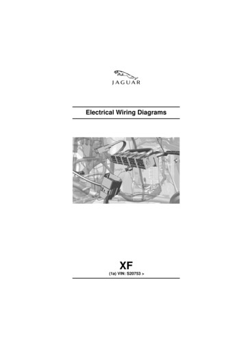
Electrical Wiring DiagramsXF(1a) VIN: S20753
BY APPOINTMENT TOHER MAJESTY QUEEN ELIZABETH IIMANUFACTURERS OF DAIMLER AND JAGUAR CARSJAGUAR CARS LIMITED COVENTRYBY APPOINTMENT TOHIS ROYAL HIGHNESS THE PRINCE OF WALESMANUFACTURERS OF DAIMLER AND JAGUAR CARSJAGUAR CARS LIMITED COVENTRYElectrical Wiring DiagramsXF(1a) VIN: S20753 Published by Technical Communications, Jaguar Cars LimitedPublication Part No. JLR 16 04 21 1E
PREFACEWhile every effort is made to ensure accuracy, design changes to the vehicle may be made in the period between the completionof this publication and the introduction of vehicles.PREFACEAll rights reserved. No part of this publication may be reproduced, stored in a retrieval system or transmitted in any form, electronic,mechanical, recording or other means without prior written permission from Jaguar Cars Limited.Paper copies of this document are uncontrolled, always refer to the electronic source material for the latest information. 2011 Jaguar Cars Limited07/2011
ABBREVIATIONS. xiUSING THIS PUBLICATIONHealth and safety. xiiUsing this publication. xiiSection numbering. xiiiUnderstanding the circuit diagrams . xiii204-04 - WHEELS AND TIRESTire pressure monitoring system . 1205-02 - REAR DRIVE AXLE AND DIFFERENTIAL. 2206-05 - PARKING BRAKE AND ACTUATION. 3206-09 - ANTI-LOCK CONTROL. 4. 5211-04 - STEERING COLUMNSteering wheel . 6Steering Column Adjustment . 7303-03 - ENGINE COOLINGPV8 (5.0L) . 8DV6 . 9D4 . 10303-06 - STARTING SYSTEMPV8 (5.0L) . 11D4 . 12D4 . 13303-14E - ELECTRONIC ENGINE CONTROLS - PV8 (5.0L)Vehicle interface - Part 1 .Actuators - Part 1 .Actuators - Part 2 .Actuators - Part 3 .Actuators - Part 4 .Sensors - Part 1 .Sensors - Part 2 .Sensors - Part 3 .Sensors - Part 4 .Sensors - Part 5 .Emissions - Part 1 .Emissions - Part 2 .Coolant pump - PV8SC .14151617181920212223242526303-14B - ELECTRONIC ENGINE CONTROLS - DV6 (3.0L)Vehicle interface - Part 1 .Vehicle interface - Part 2 .Vehicle interface - Part 3 .Sensors - Part 1 .Sensors - Part 2 .Sensors - Part 3 .Sensors - Part 4 .Actuators - Part 1 .Actuators - Part 2 .Actuators - Part 3 .Actuators - Part 4 .Emissions - Part 1 .Emissions - Part 2 .07/201127282930313233343536373839v
303-14A - ELECTRONIC ENGINE CONTROLS - D4Vehicle interface - Part 1 .Vehicle interface - Part 2 .Vehicle interface - Part 3 .Vehicle interface - Part 4 .Actuators - Part 1 .Actuators - Part 2 .Actuators - Part 3 .Sensors - Part 1 .Sensors - Part 2 .Sensors - Part 3 .Emissions .4041424344454647484950307-01 - AUTOMATIC TRANSMISSIONPV8 (5.0L) .DV6 - 6 speed .DV6 - 8 speed .D4 .51525354310-01 - FUEL TANK AND FUEL LINESPetrol - PV8 5.0L . 55DV6 . 56D4 . 57310-03 - SPEED CONTROLPetrol - PV8 5.0L .Adaptive .DV6 .D4 .58596061412-01 - CLIMATE CONTROLPart 1 .Part 2 .Part 3 .Part 4 .62636465412-02 - AUXILIARY CLIMATE CONTROLHeated - front . 66Heated - rear . 67413-01 - INSTRUMENT CLUSTERPart 1 .Part 2 .Part 3 .Part 4 .68697071413-13 - PARKING AIDFront . 72Rear . 73Rear view camera . 74414-01 - BATTERY, MOUNTING AND CABLESBattery cables - Petrol (PV8 5.0L) . 75Battery cables - DV6 . 76Battery cables - D4 . 77Engine junction box - Common 1 . 78Engine junction box - Common 2 . 79Engine junction box - PV8 EMS (5.0L) . 80Engine junction box - Petrol Emissions . 81Engine junction box - DV6 EMS . 82Engine junction box - D4 . 83Engine junction box - Visibility . 84Central junction box . 85Rear junction box . 96Ground distribution - Petrol EMS . 104Ground distribution - Diesel EMS . 105Ground distribution . 106vi07/2011
414-02 - GENERATOR AND REGULATORCharging - PV8 5.0L . 116Charging - DV6 . 117Charging - D4 .
TV Television ULEV Ultra low emission vehicle USB Universal serial bus VICS Vehicle information control system. USING THIS PUBLICATION x 07/2011 USING THIS PUBLICATIONHealth and safety Always follow health and safety guidel
