Transcription
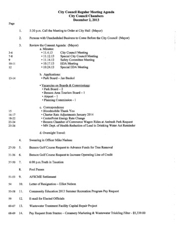
Ralph Gable, WA2PUX658 French Glen, Oregon, WI 53575; wa2pux@gmail.comRemote Rig OperationA creative approach to remote transceiver control.My ham radio career started in 1970. Myshack was in the corner of the basement.Ever since, my shack has always ended upin the basement if we had a basement toput it in.We moved into our present home in2002. As always, my shack went into thebasement for lack of anywhere else to putit. Granted, I ended up with a very nicelydone corner of the basement, but it was abasement, after all. I wanted to get out of thebasement without having to actually movethe shack; there would be too many largeholes to drill.It occurred to me, “Why not operate myrig remotely?” My Kenwood TS-2000 hadthat capability. It talked to an RS-232 port.One small hole between the shack and thebedroom to fish an RS-232 cable and I’d beset -- except I still didn’t have audio. It is allwell and good to be able to operate the radioremotely, but does little good if I cannot hearit! Okay, so I run speaker and microphonecables, too.I didn’t want to run these analog signalsany distance in an RF environment. I have awired and wireless network in my home. So,why couldn’t I use the existing Ethernet network to transmit control and audio?Controlling the Rig RemotelyThe control side was quite easy.Lantronix makes RS-232 to Ethernet adapters. These come with software to make yourcomputer “think” it is talking to a COM port(virtual COM port, RS-232). So, the software that controls the rig sees a COM portand is happy. The control signals happily zipback and forth over the Ethernet and the rigsees an RS-232 port talking to it. We’re halfway there.Audio to and from the Rig, theBiggest ChallengeI had the same problem, though 10QEX – November/December 2011The 3CX Phone System Management Console showing the settings for the shack(GrandsStream HT286) extension.no audio. My original plan was to build afull duplex audio interface that talksRS-232 and utilizes the second port of myLantronix UDS2100 RS-232-to-Ethernetadapter. This would require software expertise on the computer end to talk RS-232 tosend and receive audio from the sound cardto another virtual COM port. I didn’t havethat expertise. The project stalled .at leastuntil I discovered Voice Over IP (VOIP)technology.This technology has been around a longtime. Magic Jack and Vonage are two common carriers who use VOIP to providetelephone service. But, how do I use thistechnology in my application?Getting Audio to and from theEthernetGrandStream (among others, I’m sure)have Analog Telephone Adapters (ATA) thatinterface between standard VOIP networkand any analog telephone. I purchased aGrandStream HT 286 for under 30 off theInternet. This requires that I have a VOIPnetwork for it to talk to. How do I get a VOIPnetwork in my house? This was way easierthan I thought.Setting Up a VOIP Network3CX has free, downloadable software todo the job (www.3cx.com/phone-system/index.html). One application is the VOIPsystem that resides on a computer on yournetwork.This was a little daunting to me as I wassailing into unknown waters. I had helpfrom Matthew Orr of InfoSys Consulting,Inc. (www.InfoSysHelp.com) in gettingthis set up. My personal thanks to him;he was a great resource. Later in this articleI’ll describe how to go about configuringthe GrandStream HT286 with the VOIPsystem.
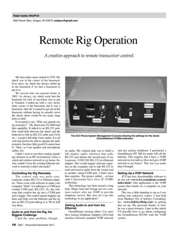
Turning Your Computer Into a PhoneThe second needed software that you candownload free from 3CX is the Softphone(www.3cx.com/VOIP/voip-phone.html).It is an application that sets up a VOIPtelephone on your computer. You use theSoftPhone to call the GrandStream ATAdown in the shack. With this SoftPhoneloaded on every computer in the house, youcan make calls between computers (eachcomputer becomes an extension with videophone capabilities) and you can connectto your rig’s audio from any computer! I’lldescribe later how to set up SoftPhone.Interfacing the ATA with the Rig’sAudio More ControlWe’re mostly there, but not quite. I havethe audio in the shack now in the form of ananalog telephone signal. How do I get it intoand out of the rig? Most of you are probably ahead of me on this. If you are thinking“phone patch,” you are 100% correct. But,this phone patch has to have certain functionality to make it convenient for this application. As a minimum it needs to: Answer the phone and connect to the rigautomatically like an answering machinedoes after a set number of rings Allow you to hang up the extensionremotelyFor even more convenience, I’d like it toallow me to turn on the power to the rig’spower supply and connect the antennas tothe rig.If you are thinking “ring detector andcounter” to take care of the first requirement,you got that right. If you are thinking “touchtone decoder” for the second requirementand the added extra, you got that right, too.So, that is what I did. I built a phonepatch with a ring detector and counter sothat it would automatically answer the phoneafter four rings. I added a touch tone/DTMFdecoder to provide control. The DTMFdecoder I chose gives me the potential ofcontrolling up to 16 devices with a singlekey press for each. Of course, one of those istaken up with the hang up functionality andanother for the power up functionality. Youare still left with 14 more things you can doremotely. These lie fallow in my design, forthe moment.The downside of the DTMF decoder isthat it doesn’t work when there is any amountof audio on the telephone line. So, it has tobe quiet on the line to use this. Switchingantennas with the din of a pile-up going onjust won’t happen. Mute rig, switch antennas,un-mute rig.One More Degree of FreedomNow, to give myself yet one more degreeof freedom, I purchased a Bluetooth handsfree headset and a USB Bluetooth interface.Now I do not need a wired microphone. TheSoftPhone can be configured to use the PCspeakers for its speakers and the Bluetoothheadset for its microphone. The whole system looks something like the diagram shownin Figure 1.The Phone Patch DetailsBack in the early 1970s I built a rudimentary phone patch. Believe it or not, I kept theguts of the patch all these years, stuffed awayon a box full of Styrofoam noodles. When Istarted looking for more technical information for my new patch, I was amazed at whodidn’t have it. I did find what I was lookingfor, but it wasn’t where I expected it to be.In the end, it wasn’t rocket science and Ididn’t expect it to be. After all, I was just 16when I built my first one, but it didn’t havethe needed bells and whistles that this oneneeded to have.Let’s walk through the schematic inFigure 2. The basic phone patch portion ofthe schematic is shaded in gray. The relaycontacts that are connected across C15 maybe replaced with a SPST switch. The purposefor the diodes included in the design acrossthe speaker and microphone is to preventlarge voltage swings in the event of the ringsignal. They are there for protection of thetransceiver. Please note that the pin numbersthat appear on the transformer may not bethe pin numbers that apply to the transformeryou choose to use. The transformer is a600 Ω primary connected to the telephoneline. The speaker winding is a 600 Ω secondary. The microphone winding is a150 Ω secondary. The primary/secondarythat is used for the ring detector is a 150 Ωwinding.The Ring DetectorThe ring signal is an ac signal. There area number of ways I could have done this, butQX1111-Gable01In ShackNetworkRS-232 toEthernet AdapterRS-232 Control onePatchRigMicAnywhere You WantWireless or Wired NetworkBluetoothRequired software on one computer per VOIP network** VOIP System Software (e.g. 3CX free download)Required software on every computer:** Virtual Port Software (e.g. Lantronix)** VOIP SoftPhone (e.g. 3CX free download)** Rig Control Software (e.g. Ham Radio Deluxe)Figure 1 – System diagram.QEX – November/December 201111
Figure 2 -- Main phone patch. The basicphone patch portion is shaded in gray.12QEX – November/December 2011
QEX – November/December 201113
Figure 3 — DTMF Decoder and Control.14QEX – November/December 2011
QEX – November/December 201115
I settled on an ac input opto-isolator. The acring signal coming from the transformer goesthrough a current limiting resistor to a diodecircuit (clipper) designed to limit the voltageto be applied to the opto-isolator circuit to nomore than the zener voltage plus the forwardvoltage drop of the other diode that is inseries. This is still an ac signal.The next step is a current limiting resistorto the input of the opto-isolator (PS2805-4).The selection of the limiting resistor is basedon the forward drop of the input of the optoisolator and the current you want to pushthrough it. I added a 3.3 µF capacitor to turnthis same circuit into a low pass filter. Thisway stray clicks and the like that may appearon the telephone line do not get counted as abona fide ring signal.The output side of the opto-isolator isan open collector with a following commonemitter amplifier (2N3906). The object is tomake the rise and fall time of the incomingsignal as quick as we can. Digital gates arenot real happy with slow slew rate signals. Tofinish the processing, I stuck a Schmitt trigger inverter between the opto-isolator outputand the counter input; this finishes squaringthe edges up. Now we have a nice, truly digital signal to apply to the counter.To follow the signal a little bit just forclarity of understanding A ring signal occurs The input side of the opto-isolator conducts The output side of the opto-isolator conducts and its collector goes low This pulls the base of the 2N3906 lowcausing it to conduct, connecting the collector to Vcc (VCOLLECTOR Vcc – 0.2 V 4.8V). The collector goes high. When the ring signal stops, the collectorof the 2N3906 drops low again.The Ring CounterAdmittedly, the counter circuit does looka bit strange. Thinking this through, I wantedthe counter to stop counting after it reached acount of four. That means that bit Q2 wouldgo high. I had to come up with a way to dothis. The CD4518 has a Clock Enable input.If the Clock Enable is high, then positivetransitions on the clock cause it to increment.On the other hand, if the clock input is low,then negative transitions on the Enable inputcause it to increment. If the clock is heldhigh, then transitions on the Enable do nothing. That is just what the doctor ordered.I tied the counter’s Q2 (bit 2 of 0 through3) output to the CLK input and the outputof the opto circuit to the Enable input of thecounter. Now the counter increments a countat the cessation of each telephone ring. Onceit reaches a count of four, then it quits counting. The only thing that will allow it to count16QEX – November/December 2011again is a reset.The counter is reset either by the PWRRESET signal or the “#” output (HANGUP) of the DTMF decoder. To reset thecounter is to hang up the phone.The output of the counter goes high whenthe phone patch is supposed to answer thephone. This drives three relay driver inputs.The first (RL1) connects the phone patchto the phone line, answering the phone. Thesecond (LS1) connects the rig’s speaker output to the audio input of the patch. The third(LS2) connects the audio output of the patchto the microphone input of the rig.Power Up ResetThe power up reset is nothing more thanan RC network whose output goes high atpower up and then drifts low as the capacitorcharges. The pushbutton across the capacitor is the reset button for manual reset. Itpulls the PWR RESET signal high anddischarges the capacitor. Once released, thePWR RESET signal drifts low again just asif the power were just turned on.DTMF DecoderThe DTMF, or touch-tone, decoder is an offthe shelf DTMF receiver, an HT9170 which isavailable through Newark Electronics. SeeFigure 3. There is nothing special aboutthis circuit. I took the circuit right out ofApplication 1 on page 8 of the datasheet.One of the outputs of the DTMF receiveris the DV output which goes high when avalid DTMF tone pair is detected. More onthis later.The HT9170 presents the decodedDTMF tones as four bit binary numbers. Tomake this truly useful, this has to be furtherdecoded. I chose a 4:16 decoder/demultiplexer, the 74HC154. It is a simple matterof connecting the four bits coming out ofthe DTMF receiver to the four bits of the4:16 decoder. The decoder also has enableinputs. The output of this decoder will notbe asserted unless these enable inputs areboth low. So, we invert the DV signal fromthe DTMF receiver to give us an active lowfor these inputs. This prevents the output ofthe decoder from being asserted unless theDV signal is asserted (valid DTMF tone pairreceived by the receiver).Table 1DTMF Y9Y10Y11Y12Y13Y14Y15DTMF890*#ABCWe now have 16 fully decoded controls tobe used. They are defined in Table 1.Control CircuitryThe output of the 74HC154 is negativelyasserted. That means that the output goeslow when it is true. I chose to use the “#” toremotely hang up the phone patch and the “*”to toggle auxiliary relay contacts on and off,which I plan on using to control the ac powerto the power supply that powers the rig.The first step of this control is to invertthe output of the decoder that I have chosento use. The “DTMF Pound not” becomes“Hang Up,” which is positively assertedwhen the user wants to disconnect the phonepatch from the ATA by pressing the “#” keyon their Softphone.The “DTMF Asterisk not” becomesthe positively asserted “DTMF Asterisk.”This is used to drive the clock input of aD Flip Flop. The flip-flop has its Q not output connected to its D input so that the Q output toggles at each clock edge it sees.To make sure that it comes up in theright state, the PWR Reset signal is usedto reset it to the Q low state at power up.Furthermore, we want it to reset wheneverthe phone patch is not connected to the ATA.So, I use an OR gate with the Pwr Reset signal on one input and the “Hang Up” signalon the other. The OR gate’s output becomesthe “Asterisk Reset.”The Q output of the flip-flop serves asthe input of the relay driver. When Q is high,then the relay is engaged. When it is low, itis disengaged.All of the other outputs from the 4:16decoder just sit there waiting to feel useful.And, someday, I may just help them to feelthat way. For the time being, they will justhave to wait.Station ControlI chose to use the Asterisk relay contactsto control a relay that turns on the primarypower to the rig’s power supply. The outputof the rig’s power supply (12 Vdc) suppliespower to my Kenwood TS-2000. It alsoactivates the antenna relays. These relaysconnect the antennas to ground when notactivated and to the rig when activated. Theserelays are 10 kW RF relays I bought fromVector Solutions (www.arraysolutions.com/Products/rf relays.htm). I mountedthem in an EMI shielded aluminum box fromBud (AN-1322). To be a little more cautious,I also added additional lightning arrestors tothe antenna lead in cables.How to Set Up the VOIP System andIt’s PeripheralsThe first step is making your PC a “staticIP” box. To do this, follow the following
steps for Windows XP: Open a “Command Prompt” window. Type “ipconfig /all” and press enter. Note the following entries: IPAddress: . . SubnetMask: . Default Gateway: . DNS Servers:. . . . . Click “Start” and then “Control Panel” Double click on “Network Connections” Right click on the “Local AreaConnection” icon that represents your LANconnection and then click on the “Properties”pop-up menu item. Click on the “Internet Protocol (TCP/IP)” entry in the “This connection uses thefollowing items:” area and then click on the[Properties] button. The “Internet Protocol (TCP/IP)Properties” dialogue box opens. Click on the“General” tab. You will most likely see the“Obtain an IP address automatically” radiobutton selected. Select the “Use the following IPAddress” radio button.In the IP address, enter the IP addressthat you got from the Command Promptwindow except the last number. Choose anew number for this that is at least 20 higherthan the number you got from the CommandPrompt window. This makes sure that othercomputers/devices that connect to yourhome network that “obtain an IP addressautomatically” will not be assigned the IPaddress of this computer if they do so whenyour computer is off at the time they connect.Otherwise, you will get an IP address collision on your network and this is not pretty. Click on [OK] and [OK] and restart yourcomputer. Install the 3CX PBX Phone Systemfrom l When asked for the number of digits inthe extension, I put two. They will eventually ask you for addingextension information. I used the following:Extension Number: 10First Name: shackLast Name: ---left blank--Email address: ---left blank--Mobile Number: ---left blank--ID: 10Password: 10The 3CX Phone System Management Console showing the settings for the computer (3CXPhone) extension.The author’s remote control system package.QEX – November/December 201117
Add another extension for the 3CX phonefor the computer. I used the following:Extension Number: 13First Name: RalphLast Name: GableEmail address: ---left blank--Mobile Number: ---left blank--ID: 13Password: 13 Complete the installation of the 3CXPBX Phone System. Install the 3CX Phone for the computerthat you downloaded from: www.3cx.com/downloads/3CXPhone6.msi Create a new account on the 3CXSoftPhone.Account Name: ---anything you want tocall it---Caller ID: 13Extension: 13ID: 13Password: 13My Location:I am in the officeLocal IP IP address chosen above ofPBX Click on [OK] and then [OK] again.Not connected .reading configuration on hook Now for the Grandstream HT286 Locate and record the MAC address ofthe HT286 (usually on the label on the bottom) Connect the HT286 to an analog telephone. Connect the HT286 to power with itsadapter. The following steps come directlyfrom an application note found on the3CX site tml).“Configuring GrandStream HandyTone486(487),286(287), ATA for 3CXPhone System” Reset it to factory defaults. Pick up the headset and press “****”.This will start up a Voice Prompt Menu.18QEX – November/December 2011Now press “99”. Dial the MAC of the device,where a. A 22b. B 222c. C 2222d. D 33e. E 333f. F 3333For example, if the MAC address is000b8200e395, it should be encoded as“0002228200333395” Setup the HT286 to work with the 3CXPBX system Connect the LAN to the Wan port of theHandyTone Connect an analog phone to theHandyTone phone port. Pick up the headsetand press “****”. This will start up a VoicePrompt Menu. Now press “02” to listen to theIP address that was assigned to the device bythe DHCP server Enable the wan side Web access, dial“****” and then “129” Launch a browser and go to the IPAddress determined or configured earlier.The default username is “admin” Select the “Advanced Settings 1” tab. Set the “SIP Server” field to the IPAddress or FQDN of the server on which3CX Phone System is installed – in thisexample 10.172.0.2 Set the “Outbound Proxy” field to thesame value as in step 13 above. The “SIP User ID” field should matchthe “Extension Number” field of the extension created for this phone in the 3CX PhoneSystem Management Console In the “Authenticate ID” and“Authenticate Password” fields enter the IDand Password that you entered for the extension in the 3CX Phone System ManagementConsole. These fields must match theAuthentication ID and Password set forthat extension in the 3CX Phone SystemManagement Console The “Name” field is optional. A suitablevalue would be the name of the user usingthis phone Set the “Preferred Vocoder” to choice1: PCMU, choice 2: PCMA. The settings forchoices 3 to 7 will not come in use since theywill not be used by 3CX Phone S
Magic Jack and Vonage are two com-mon carriers who use VOIP to provide telephone service. But, how do I use this . download free from 3CX is the Softphone . You use the SoftPhone to call the GrandStream ATA down in the shack. With this SoftPhone loaded on every computer