Transcription
ADVANCED DRIVER PROGRAMMINGEVERset User ManualUser Manual Rev1.410/03/2018
Table of Contents1. Introduction . 22. Computer System Requirements . 23. Definitions System Definitions . 3 Setting Definitions . 34. Getting Started/Setup Programming Software . 5 Programming Hardware . 5 LED Drivers with Compatible Programming Interface . 5 Logging into EVERset . 65. Programming Interfaces: RFID, Wired and ESI . 76. Engineering Mode Initial Screen Layout – Products Screen . 9 Reading a Driver’s Programmed Values . 10 Creating a Profile . 14 Setting the Dimming Curve and Values . 15 Setting Lumen Maintenance . 16 Saving Profiles. 17 Quick Programming through Engineering Mode . 20 Profile Programming through Engineering Mode . 24 Additional Profile Options . 25 Additional Menu Options . 26 Printer Setup. 277. Production Mode. 288. UserManagement Setup Adding Users . 29 Production Permissions . 29www.unvlt.com1 Page
1. IntroductionThe EVERLINE Advanced Driver Programming system allows designers to customize LED Driverparameters with the EVERset graphical user interface and a compatible programming tool. Thissystem will set the driver’s minimum and maximum output currents, dimming curves, dimmingcontrol voltages, and to enable the dim to off command. Specific configurations can then be setand saved for production use. Programming capabilities will vary depending on the specificdriver family.The programming tool will also “read” and display values already programmed into a driver,including the driver’s part number.The programming of the LED driver is done with a programming tool connected to a computerwith a USB cable. The programming tool can be used to program compatible drivers via a wiredor wireless connection depending on the specific tool and driver.2. Computer System RequirementsThe minimum PC requirements for the EVERset software are: 512MB RAM1 USB Port (v2.0)Operating System: Microsoft Windows 7/8/10FTDI driversHardware Requirements Handheld Programming Toolo LDPC000A Programming Tool for wired or wireless interfaceso LDPCEL0A Programming Tool for RS-232 interfacesEVERset Programming SoftwarePrinter (Optional)www.unvlt.com2 Page
3. DefinitionsThe programming tool is for use in setting the output parameters of compatible constant currentdrivers. The controlled settings and their definitions are listed below:System DefinitionsEVERset Programming SoftwareGraphical User Interface (GUI) loaded onto a computer for establishing programmed settingsfor compatible Everline drivers.LDPC000A Programming ToolHandheld programming tool connected to a computer via USB that is used to program selectLED drivers via a wired or wireless (RFID) interfaceLDPCEL0A Programming ToolHandheld programming tool connected to a computer via USB that is used to program selectLED drivers via a RS-232 interfaceUserManagement SoftwareThis program (installed along with EVERset) is used to set up new users with passwords andaccess level permission capabilities on a computer. Production mode settings are alsoestablished with this program.Setting DefinitionsOutput CurrentThis is the driver’s output current when the dimming control is set at full output or when thedriver is not connected to a dimming control.Minimum Dim Current:This is the driver’s output current when connected to a control set to the minimum dimmingcontrol voltage.Dimming Curve:The 0-10V dimming curve can be set to Linear, Soft Start or Logarithmic. The curves aredisplayed with an accompanying graph in EVERset.Full Bright Control VoltageThis is the minimum voltage on the 0-10V control range that will provide maximum outputcurrent. This is commonly set around 8V to allow for variances in dimming controls.Full Dim Control Voltage:This is the maximum voltage on the 0-10V control range that will provide the minimumoutput current. This is typically set around 1V to allow for variances in dimming controlsDim-to-off:This is the functionality that turns off the output current while the driver still has powerconnected to it.Dim-to-Off Control Voltage:This is the control voltage where the driver will go in the off mode. Any voltage below thiswill also result in the off mode.www.unvlt.com3 Page
Lumen MaintenanceThis feature increases the output current of the driver over time to compensate for thelumen depreciation of the LED module. Initial and final drive currents along with thecompensation period are adjustable.RFIDRadio Frequency Identification for wireless programming of a driver. This uses near fieldcommunication (NFC) between the driver and the configuration tool for programming valuesinto the driver.MDCMulti-Driver Configuration for programming or reading a compatible driver with leadsconnected to the LDPC000A programming tool. This can be used with specific drivers thatare compatible with EVERset but do not have wireless programming capabilities.ProductsProducts shown in this list use the EVERset software for programming. Additional productswill continue to be added through updates.ProfilesThe saved set of all values for a specific driver setting. These can be recalled forprogramming.www.unvlt.com4 Page
4. Getting Started/Setup Programming Software The Complete EVERset Program is installed with the setup file name EVERset x.x.x.exe(x values will change with revision updates). This file may require administrator access on a computer for installation of: EVERset ProgramThe EVERset program is used for all programming applications fromcreating driver configurations, saving driver profiles, to productionprogramming. UserManagementThe UserManagement program is used to manage and create user names,passwords, and to set the access levels of production, engineering andadministration. For more detailed information refer to section 13 UserManagement Setup.Note: Administration password will be provided separately Program Data File Location A program data file will be installed in the folder C:\ProgramData\ULT thatcontains: Saved Program Configuration Profile files in ProfileLists Help information Driver database configuration files Programming Hardware Programming Tool: P/N LDPC000A Connect the programing tool to a USB port on the computer for programming. The programming tool has indicator lights that will illuminate when connected toa powered USB port The programming tool also has a connector receptacle for use when tuningdrivers that do not have wireless tuning capabilities and require MDC wiredtuning. Programming Tool: P/N LDPCEL0A Connect the programming tool to a USB port on the computer for programming. The programming tool has a RJ45 connector for use with compatible LED drivers. LED Drivers with compatible programming interface Only Everline drivers that are listed for wireless programming, MDC wiredprogramming or ESI RS-232 programming can be programmed through EVERset. The drivers with wireless programming will have a small programming antennathat looks like a small circuit board either next to the connectors or behind aplastic cover in the side of the driver. See https://unvlt.com/support/led-driver-tuning/ for a list of compatible drivers.www.unvlt.com5 Page
Logging into EVERset Launch the EVERset program and enter the Username and Password to get started. The username and password will correspond to an account setup for engineeringmode or production. This will determine the functionality allowed when EVERsetis launched. See Section 8: UserManagement Setup for information on setting up useraccounts.www.unvlt.com6 Page
5. Programming Interfaces: RFID, Wired and ESIWithin the Products menu bar as indicated above there is the option to Read and Program in eitherthe RFID, Wired or ESI mode.RFID uses near field communication to perform these functions using the LDPC000A programmingtool and driver antenna. RFID programming programs one driver at a time. When EVERset is in RFIDread mode, the LDPC000A programming tool will be continuously looking for an RFID tag to read.Wired uses leads connected directly to the driver from the LDPC000A programming tool andcommunicates via MDC (Multi-Driver Configuration) for programming. The leads are connectedbetween the configuration tool and the dimming control leads of the driver. When EVERset is in theWired read mode, the black button on the LDPC000A programming tool must be pressed to readthe driver that is connected to the tool. Each time a new driver is connected, the black button mustbe pressed on the LDPC000A to read the driver.Two harnesses with leads for programming are provided with the configuration tool and plug into asocket adjacent to the USB cable. One harness has fast connectors (as shown in the picture)designed to program drivers with leads. The other harness has pin terminals and is designed for usewith drivers that have terminal blocks.Wired programming can program four drivers simultaneously under the following conditions: Four of the same models drivers with the same profile.Three different model drivers with two of the same drivers having the same profile.Only one profile per driver per model, different profiles of the same model cannot beprogrammed simultaneously.www.unvlt.com7 Page
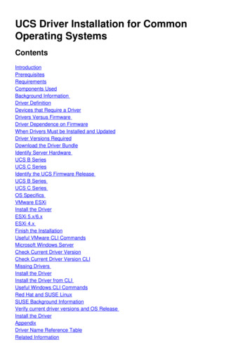
ESI programming uses the LDPCEL0A programming tool which has a male RJ-45 connector thatconnects directly to the female RJ-45 adapter on a compatible driver.When EVERset is in the ESI read mode the black ‘Read’ button at the top of the screen must beclicked to read the driver connected to the LDPCEL0A programming tool. Each time a new driver isconnected, the ‘Read’ button must be clicked to read the driver.www.unvlt.com8 Page
6. Engineering ModeInitial Screen Layout – Products Screen1. Indicates that the program is in the Products Screen. Note: Clicking on the adjacent Profiles tab willaccess the Profiles Screen.2. The “OFF” indicates that the program is NOT in the Read Mode. To enter the Read Mode click onthe adjacent arrow and “ON” will appear in green. The Mode is also displayed in the blue statusribbon.3. This indicates the model currently on the screen for programming or developing a profile. Fordifferent models, scroll down the list and click on them. The Search window at the top of theproducts list can be used to limit the list for easier selection. By typing in a partial catalognumber, the list can be narrowed down. Example “30” will provide only part numbers thatcontain “30”. The same can be done with “PWX” or other sections of the part number.4. The connected status indicates if the LDPC000A programming tool is connected to thecomputer.5. This button expands the screen for better access to the programming sliders in lieu of showingthe values in the tables. For smaller monitors, this may be beneficial when working in theDimming setup screen. Clicking on the button a second time brings the screen back to the initialstate.6. Click on the arrow to minimize the product list. Clicking on the button a second time returns theproduct list back to the screen.www.unvlt.com9 Page
Reading a Driver’s Programmed Values:The current configuration of a compatible driver can be read through EVERset. Once the driver hasbeen read, the configuration can be saved for programming or modified and programmed back tothe driver through the Engineering mode.Reading a Driver’s Programmed Values through the RFID Interface:Click on Products Tab (If not already selected)Click on Read Mode so that it is ON (if not already selected)Confirm RFID Button is selectedjjjConfirm RFID Button is selectedCSet the driver on its side and place the programming tool so that it is coplanar with the antenna.The indicator lights will change to green once the program values have been read. “READ Complete”will also appear momentarily on the screen.Driver Antennawww.unvlt.com10 P a g e
For best results position the area indicated with theprogramming tool flush against the driver.directly above the driver antenna with theExample: Screen results indicate a successful read and display the driver part number andprogrammed values for output current, dimming curve, dim curve set points and lumenmaintenance.Note: the read results can be programmed to another driver of the same model or saved as a profile for futureprogramming.www.unvlt.com11 P a g e
Reading a Driver’s Programmed Values through the Wired Interface:Click on Products Tab (If not already selected)Click on Read Mode so that it is ON (if not already selected)Confirm Wired Button is selectedjjjConfirm RFID Button is selectedCPlug in the connector with the violet and gray leads to the LDPC000A programming tool. Squeezethe open connector on the terminal connected to the violet wire from the LDPC000A and plug theviolet wire from the driver into the quick connect terminal. Repeat this process to plug the graywire from the driver into the connector attached to the gray wire on the LDPC000A.Press the black button on the top of the LDPC000A to read the connected driver. Only one drivercan be connected at a time for the Wired read process. The driver configuration will display on thescreen.www.unvlt.com12 P a g e
Reading a Driver’s Programmed Values through the ESI Interface:Click on Products Tab (If not already selected)Click on Read Mode so that it is ON (if not already selected)Confirm ESI Button is selectedjjjConfirm RFID Button is selectedCPlug in the RJ45 male connector from the LDPCEL0A into the RJ45 female connector on the driver.Press the “Read” button on EVERset. The driver configuration will display on the screen.www.unvlt.com13 P a g e
Creating a Profile1. Select the Products tab2. Select the driver part number to be programmed If a driver is programmable through multiple interfaces select the desired interface in theblue status bar. The program will default on the Output tab where the only configurable parameter is outputcurrent. If the dimming curve will be configured, you can go straight to the Dimming tab as theoutput current can also be configured there.3. Click the expand view button for better viewing if necessary4. Adjust the Output current with the slider bar or arrows5. Settings can be Reset to Default if necessarywww.unvlt.com14 P a g e
Setting the Dimming Curve and Values1. Select the Dimming tab to establish dimming parameters.a. The output current can also be changed on this tab to create the full dimming profile on onetab. Note: the Output Current selected on the Output tab will populate here.2. Select the minimum Dim Current, the lowest value is determined by the driver.a. The default minimum dim current will be a percentage of the maximum output current. Thepercentage is dependent on the driver. When this option is selected the minimum dimcurrent will change when the output current is changed. Once the driver reaches the lowestminimum dim current a notification message will appear and the program will toggle over tohave the minimum dim current selected by mA level instead of percentage.b. The radio button above the mA box can also be selected. This will make the value static andit will no longer automatically change when the output current is changed.3. Select the Dimming Curve: Linear, Soft Start, or Logarithmic.a. Logarithmic provides the options for different factors. This changes how steep the curve willbe.4. Set the Full Bright Control Voltage.5. Set the Minimum Dim Control Voltage.6. If desired, enable Dim-to-Off by setting the Dim-to-Off control voltage to 0.a. Minimum Dim Control Voltage must be 0.2V higher than Dim-to-Off Control Voltage or anerror message will appear. Note: for best operation, use at least 0.5V between the minimum dimcontrol voltage and the dim-to-off control voltage.7. The Dim Curve Chart will adjust accordingly as the values are selected8. The expand window button can be used to minimize the summary boxes if needed to display thefull dimming curve graph on the screen.www.unvlt.com15 P a g e
Setting Lumen Maintenance (when applicable):Models that have lumen maintenance capabilities will have a lumen maintenance tab displayed nextto the dimming tab. Lumen maintenance allows for the driver to increase output current over theprogrammed compensation period to offset the lumen depreciation of the module.1. Where applicable, click on the LUMEN MAINTENANCE Taba. Expand the screen if necessary for better viewing.b. For best results, the Output and Dimming tabs should be configured prior to configuringLumen Maintenance.2. Click Enable to use the Lumen Maintenance function.a. Click Disable to disable the Lumen Maintenance function.b. The Lumen Maintenance tab will only appear for drivers that have Lumen Maintenancefunctionality and will not appear for others. The default setting for drivers with LumenMaintenance is disabled.3. Set the final output current in the field supplied.a. This is the maximum output current at the end of compensation period.b. This is the output current value that is displayed on the Output and Dimming tabs.4. Set the initial output current in the field supplied. This value can be set between 50% and 100%of the Output Current (Final).5. Set the Lumen Compensation Period in the field supplied.a. This is the time in hours for the driver to increase the output current from Initial to Final.b. The maximum value is 100,000 hours.6. The Lumen Maintenance percentage value is shown below the graph.www.unvlt.com16 P a g e
Saving ProfilesDriver configurations can be saved as Profiles in EVERset. Saved profiles can be recalled throughengineering mode or production mode for programming drivers.Saving Profiles for use with the RFID and ESI Programming InterfacesAfter creating a driver configuration that will be programmed with the RFID or ESI programminginterface:1. Click on Save Profile2. In the Save Profile dialog box, click on “Yes”3. In the File Name dialog box, enter the desired Profile name in the File Name field. This willbe the name of the profile shown in the Profiles tab.a. The Description field is optional4. Click OKwww.unvlt.com17 P a g e
Saving Profiles for use with the Wired Programming InterfaceDriver configurations created for use with the Wired Programming Interface have an additional stepbefore saving the configuration as a profile. After creating the configuration:1. Select the number of drivers to be programmed2. Click Add to Profile3. EVERset will switch over to the Configuration Summary List4. If additional drivers are desired to be added to this configuration, click on the driver in theProducts tab and create a new configuration. Note: Section 5 “Programming Interfaces: RFID,Wired and ESI” contains information on the quantities of drivers that can be programmed throughthe Wired Programming Interface5. When the configuration is complete, click on Save Profile.6. In the Save Profile dialog box, click on “Yes”www.unvlt.com18 P a g e
7. In the File Name dialog box, enter the desired Profile name in the File Name field. This willbe the name of the profile shown in the Profiles tab. The Description field is optional8. Click OKwww.unvlt.com19 P a g e
Quick Programming through Engineering ModeRFID Programming1.2.3.4.5.6.Set the program into Products mode and select a driver from the Products list.Set Read Mode to OFF, the text below will indicate the “Write” mode.Enable the RFID Button (if not already selected) for wireless programmingClick the Dimming tab to adjust the dimming parametersIf needed, use the Expand view button to have all of the controls on one page.Adjust the programmable outputs with the numbers or slider bars The control chart will automatically adjust with changes If using Dim-to-Off Control, the minimum Dim Control Voltage must be at least 0.2Vhigher than the Dim-to-Off Control Voltage. An error message will appear if thedifference is less than 0.2V. A Dim-to-Off Control Voltage of “0” disables this function7. Click Program Profile This loads the configuration into the LDPC000A programming tool8. Place the programming tool co-planar to the antenna on the driver in the same manner asreading the driver. The lights on the programming tool will display green when the driver is programmed The screen will also temporarily display that the driver has been programmed.Note: if switching to Wired or ESI programming, click the Clear button to remove the RFIDconfiguration from the programming tool.www.unvlt.com20 P a g e
Wired Programming1.2.3.4.5.6.Set the program into Products modeSet Read Mode to OFF, the text below will indicate the “Write” mode.Enable the Wired Programming Button (if not already selected)Click the Dimming tab to adjust the dimming parametersIf needed, use the Expand view button to have all of the controls on one page.Adjust the programmable outputs with the numbers or slider bars The control chart will automatically adjust with changes If using Dim-to-Off Control, the minimum Dim Control Voltage must be at least 0.2Vhigher than the Dim-to-Off Control Voltage. An error message will appear if thedifference is less than 0.2V. A Dim-to-Off Control Voltage of “0” disables this function7. Click Add to Profile EVERset will switch over to the Configuration Summary Listwww.unvlt.com21 P a g e
8. Click Program Profile This loads the configuration into the LDPC000A programming tool Connect the violet and gray leads from the driver to the violet and gray connectorson the LDPC000A programming tool9. Press the black button on the top of the LDPC000A programming tool The lights on the programming tool will display green when the driver is programmedThe screen will also temporarily display that the driver has been programmedwww.unvlt.com22 P a g e
ESI Programming1.2.3.4.5.6.Set the program into Products modeSet Read Mode to OFF, the text below will indicate the “Write” mode.Enable the ESI Programming Button (if not already selected)If needed, use the Expand view button to have controls on one page.Adjust the output current with the numbers or slider barClick Program Profile This loads the configuration into the LDPCEL0A programming tool Connect the male RJ45 connector from the LDPCEL0A programming tool to thefemale RJ45 connector from the driver7. Click the Write Button The screen will temporarily display that the driver has been programmedwww.unvlt.com23 P a g e
Profile Programming through Engineering ModeProfile ProgrammingThe Profile Screen allows for recalling of saved profiles and programming of these profiles throughthe Engineering Mode. This screen can be accessed by clicking on the Profiles tab beneath EVERset.1. The list of available Profiles will be displayed on the left side of the screen. A profile can befound by scrolling through the list or by typing into the search box.2. There is also an option to pull up a profile by scanning a barcode. Click on the scanner iconand then scan the barcode for the profile and EVERset will automatically load the profile.The barcode needs to be generated to match the profile name and the compatible barcodeformats will depend on the specific barcode scanner that is used.3. The selected profile will show up on the screen. Here the parameters to be programmed,along with the profile name and the driver catalog number will all be displayed.4. Click on the Program Profile button. For specific instructions on the different programminginterfaces, refer to the prior section “Quick Programming through Engineering Mode”.5. The Print Label button will become active if label printing has been enabled. See section“Printer Setup” for instructions on setting up label printing.www.unvlt.com24 P a g e
Additional Profile OptionsIn addition to loading and programming profiles, there are additional tasks available in the Profilesscreen.1. The Edit Profile button will open up the profile into the Products Tab. From thereparameters can be changed and the profile can be saved as a new profile. This is helpfulwhen creating a series of profiles for a luminaire where the only value changing is the outputcurrent.2. The Import Profile button can be used to load a profile from another location into EVERset.This can be used for sharing profiles during design or loading profiles into a separatecomputer for programming.3. The Page icon contains the following options:a. Export Profile – this allows the profile on the screen to be saved to a location other thanthe selected profile folder used by the computer running EVERset.b. Open Profiles Folder: Opens and shows profiles in the location the EVERset programuses. Profiles can then be copied from this location and then saved on a secondcomputer with the EVERset software.c. Refresh Profiles: Updates profiles on screen when new ones have been loaded. Thisneeds to be clicked if profiles have been manually loaded into the profile folder whileEVERset is in use.d. Delete Profiles: Deletes the highlighted or identified Profilewww.unvlt.com25 P a g e
Additional Menu OptionsThe following additional menu options can be accessed in EVERset by clicking on the gear wheelicon Load Default Database: Clicking on this option will load the default driver configurationdatabase file.Update Configuration Database: Updates the configuration database by downloading thelatest file from the internet or from a local drive. Note: When the local drive option is selected, thefile needs to remain in the location pointed to during the update. If the file is moved, EVERset will revert tothe default database. Printer Setup: configuration of printer setup when using a compatible printer throughEVERset. See next page for detailed instructions.Folder Locations: Allows for changing the default folders for the CSV Folder, Log Folder andProfile Folder. CSV Folder – this is the location where EVERset will generate CSV files after a successfulprogramming if the CSV export option is enabled in Production mode. The defaultlocation is C:\ProgramData\ULT\CSV Log Folder – this is the location where EVERset generates and stores log files of thesuccessful driver programmings. The default location is C:\ProgramData\ULT\Logs Profile Folder – this is the location where new profiles are saved to and where EVERsetlooks for profiles to be loaded for programming. The default location isC:\ProgramData\ULT\ProfileListsUpdate EVERset: Checks for the latest version of the EVERset program and provides anoption to update (internet access required)Log Data: Provides an exportable table of the products that have been programmed withdetails of the date, time, and configuration settings. Data can also be limited by theprogrammed date or programmed date range.www.unvlt.com26 P a g e
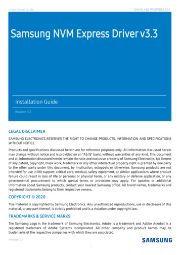
Printer SetupEVERset contains basic label printing for use with a Dymo LabelWriter 450 printer and 0.5” x 1.0”labels. If more customization is required in the label, the CSV export option is provided for use witha separate printing setup.1. Click on Select Printer and highlight the Dymo LabelWriter 450 and click Apply.2. The Dymo LabelWriter 450 will be displayed next to Printer Name.a. Check the box next to Print Both Labels if it is desired to print both labels. This selectionwill carryover to the Production Mode interface. The label content will be selected instep 4.b. Check the box next to Label Printing to enable label printing in the engineering mode.Enabling label printing for Production Mode is done in UserManagement.c. Check the box next to Automatic to have the engineering mode labels print automaticallyafter a successful programming.3. The Dymo 0.5” x 1.0” label size will be selected. No other changes need to be made to theLabel Size Selecto
Oct 03, 2018 · ESI programming uses the LDPCEL0A programming tool which has a male RJ-45 connector that connects directly to the female RJ-45 adapter on a compatible driver. When EVERset is in the ESI read mode the black ‘Read’ button at the top of the screen must be clicked to re