Transcription
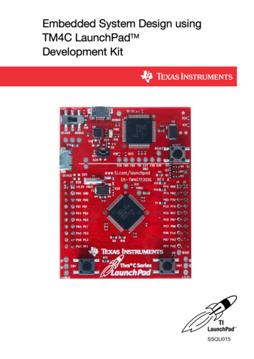
Embedded System Design usingTM4C LaunchPadTMDevelopment KitSSQU015
CopyrightCopyright 2007-2014 Texas Instruments Incorporated. Tiva and TivaWare are trademarks of Texas Instruments Incorporated. ARM and Thumb areregistered trademarks and Cortex is a trademark of ARM Limited. All other trademarks are the property of others.Please be aware that an important notice concerning availability, standard warranty, and use in critical applications of Texas Instruments semiconductorproducts and disclaimers thereto appears at the end of this data sheet.Texas Instruments Incorporated108 Wild Basin, Suite 350Austin, TX htm2June 12, 2014Texas Instruments-Production Data
ContentsPreface . 1Getting Started . 2Overview . 3Tiva C Series LaunchPad . 7Code Composer Studio . 10TivaWare Library for Tiva Platform . 18Using Tera Term . 19Experiment 1 To Blink an Onboard LED . 211.1Objective . 221.2Introduction . 221.2.1 GPIO Module . 221.3Component Requirements . 241.3.1 Software Requirements . 241.3.2 Hardware Requirements . 241.4Software . 241.4.1 Flowchart . 241.4.2 C Program Code to Blink an Onboard LED . 251.5Procedure . 261.6Observation .271.7Summary . 271.8Exercise . 27Experiment 2 Interrupt Programming with GPIO . 282.1Objective 292.2Introduction . 292.2.1 Timer . 292.2.2 GPIO Module . 302.3Component Requirements . 312.3.1 Software Requirement . 312.3.2 Hardware Requirement . 312.4Software . 322.4.1 Flowchart . 322.4.2 C Program Code for Interrupt Programming with GPIO . 332.5Procedure . 352.6Observation .352.7Summary . 352.8Exercise . 35Experiment 3 Hibernation and Wakeup on RTC Interrupt . 363.1Objective . 373.2Introduction . 373.2.1 Hibernation Module . 373.3Component Requirements . 383.3.1 Software Requirement . 383.3.2 Hardware Requirement . 393.4Software . 393.4.1 Flowchart . 393.4.2 C Program Code for Hibernate Mode and Wake up using RTC . 41iContents
Contentswww.ti.com3.53.63.73.8Procedure . 42Observation .43Summary . 43Exercise . 43Experiment 4 Interfacing Potentiometer with TIVA GPIO . 444.1Objective . 454.2Introduction . 454.2.1 Analog to Digital Conversion Module . 454.3Component Requirements . 464.3.1 Software Requirement . 464.3.2 Hardware Requirement . 464.4Software . 474.4.1 Flowchart . 474.4.2 C Program for ADC Conversion of Potentiometer Input via GPIO . 494.5Procedure . 514.5.1 Hardware Setup . 514.5.2 Implementing the Software . 534.6Observation .534.7Summary . 544.8Exercise . 54Experiment 55.15.25.35.45.55.65.75.8PWM Generation . 55Objective . 56Introduction . 56Component Requirements . 575.3.1 Software Requirement . 575.3.2 Hardware Requirement . 57Software . 585.4.1 Flowchart . 585.4.2 C Program Code for PWM Generation . 59Procedure . 625.5.1 Hardware Setup . 625.5.2 Implementing the Software . 63Observation .63Summary . 65Exercise . 66Experiment 6 PWM based Speed Control of DC Motor using Potentiometer . 676.1Objective . 686.2Introduction . 686.2.1 Pulse Width Modulation . 686.2.2 ADC Module . 696.3Component Requirements . 706.3.1 Software Requirement . 706.3.2 Hardware Requirement . 706.4Software . 716.4.1 Flowchart . 716.4.2 C Program Code for PWM based Speed Control of DC Motor . 736.5Procedure . 776.5.1 Hardware Setup . 776.5.2 Software Execution . 786.6Observation .79iiContents
Contents6.76.8www.ti.comSummary . 80Exercise . 81Experiment 7 UART - ECHO! . 827.1Objective . 837.2Introduction . 837.2.1 UART Module . 837.3Component Requirements . 847.3.1 Software Requirement . 847.3.2 Hardware Requirement . 847.4Software . 857.4.1 TeraTerm Setup . 857.4.2 Flowchart . 857.4.3 C Program Code for UART - Echo . 867.5Procedure . 887.6Observation .897.7Summary . 897.8Exercise . 89Experiment 88.18.28.38.48.58.68.78.8Interfacing an Accelerometer with TIVA using I2C . 90Objective . 91Introduction . 91Component Requirements . 938.3.1 Software Requirement . 938.3.2 Hardware Requirement . 93Software . 948.4.1 Flowchart . 948.4.2 Steps for Creating, Building and Debugging Project . 96Procedure . 978.5.1 Hardware setup . 978.5.2 Software Execution . 98Observation .98Summary . 98Exercise . 98Experiment 9 USB Bulk Transfer Mode . 1009.1Objective . 1019.2Introduction . 1019.2.1 Universal Serial Bus Controller . 1019.3Component Requirements . 1029.3.1 Software Requirement . 1029.3.2 Hardware Requirement . 1029.4Software . 1029.4.1 Flowchart . 1039.5Procedure . 1049.6Observation . 1069.7Summary . 1079.8Exercise . 107Experiment 10 Using IQmath Library . 10810.1Objective .10910.2Introduction . 10910.2.1 IQmath Library . 10910.2.2 Trigonometry . 109Contentsiii
t Requirements . 11010.3.1 Software Requirement . 11010.3.2 Hardware Requirement . 110Software . 11010.4.1 Flowchart . 11110.4.2 Addition of IQmath Library . 11110.4.3 C Program Code for Calculation using IQmath Library . 112Procedure . 114Observation . 114Summary . 114Exercise .114Experiment 11 Setting of Static IP Address . 11611.1Objective .11711.2Introduction . 11711.2.1 CC3100 Booster Pack . 11711.3Component Requirements . 11811.3.1 Software Requirement . 11811.3.2 Hardware Requirement . 11811.4Software . 11911.4.1 Flowchart . 11911.5Procedure . 12111.5.1 Hardware Setup . 12111.5.2 Steps for Creating, Building and Debugging Project . 12111.6Observation . 12511.7Summary . 12511.8Exercise .125Experiment 12 CC3100 as WLAN Station . 12612.1Objective .12712.2Introduction . 12712.3Component Requirements . 12812.3.1 Software Requirement . 12812.3.2 Hardware Requirement . 12812.4Software . 12912.4.1 Flowchart . 12912.5Procedure . 13112.5.1 Hardware Setup . 13112.5.2 Steps for Creating, Building and Debugging Project . 13112.6Observation . 13312.7Summary . 13412.8Exercise .134Experiment 13 Setting Up CC3100 as a HTTP Server . 13513.1Objective .13613.2Introduction . 13613.3Component Requirements . 13713.3.1 Software Requirement . 13713.3.2 Hardware Requirement . 13713.4Software . 13813.4.1 Flowchart . 13813.5Procedure . 14013.5.1 Hardware Setup . 140ivContents
Contents13.613.713.8Contentswww.ti.com13.5.2 Steps for Creating, Building and Debugging Project . 140Observation . 142Summary . 144Exercise .144v
www.ti.comList of 16-26-36-46-56-66-77-17-27-37-48-1Tiva C Series TM4C12x Microcontroller Architecture . 4Pin Diagram of TM4C123GH6PM . 5Functional Block Diagram of ARM Cortex-M4F Processor . 6EK-TM4C123GXL . 7Power Select Switch Position . 9CCS Functional Overview . 10CCS Edit Perspective . 11CCS Debug Perspective . 12Workspace and Projects (as viewed in CCS) . 12Workspace and Projects . 13New CCS Project Creation . 14Project Properties Window . 15File Search Path . 16Debug Environment . 17Tera Term New Connection Window . 19Tera Term Serial Port Setup Window . 20Tera Term Terminal Setup Window . 20Functional Block Diagram . 22LaunchPad Schematics for GPIO Connected to LEDs . 23Flowchart for Blinking an Onboard LED . 25Functional Block Diagram . 29LaunchPad Schematics for GPIO Connection with LEDs . 30Flowchart for Interrupt Programming with GPIO . 32Functional Block Diagram . 37Flowchart for Hibernate Mode and Wake up using RTC . 40Functional Block Diagram . 45Flowchart for ADC Conversion of Potentiometer Input via GPIO . 48Connection Diagram for Potentiometer with EK-TM4C123GXL . 51Hardware Setup . 52Digital Output for Three Different Positions of the Potentiometer . 53PWM Output for Analog Signal .56Functional Block Diagram . 57Flowchart for PWM Generation .59Connection Diagram for Oscilloscope with EK-TM4C123GXL . 62Hardware Setup . 63PWM Output for 10% Duty Cycle . 64PWM Output for 20% Duty Cycle . 64PWM Output for 50% Duty Cycle . 65PWM Output for 60% Duty Cycle . 65Functional Block Diagram . 68Analog Output for PWM Signal .69Flowchart for PWM based Speed Control of DC Motor using Potentiometer . 72Connection Diagram for Potentiometer and DC Motor with EK-TM4C123GXL . 77Hardware Setup . 78Digital Output and PWM Signal for Position 1 . 79Digital Output and PWM Signal for Position 2. 80Functional Block Diagram . 83Tera Term Serial Port Setup Window . 85Flowchart for UART - Echo .
List of Tables. vi www.ti.com. List of Figures. 1
