Transcription
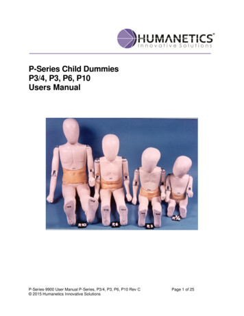
P-Series Child DummiesP3/4, P3, P6, P10Users ManualP-Series-9900 User Manual P-Series, P3/4, P3, P6, P10 Rev C 2015 Humanetics Innovative SolutionsPage 1 of 25
For information on Humanetics products, please visit our web site atwww.humaneticsatd.comor contact:Humanetics Innovative Solutions47460 Galleon DrivePlymouth, MI 48170, USATelephone: 734-451-7878Fax: 734-451-9549No part of this publication may be reproduced, stored in a retrieval system ortransmitted in any form or by any means, electronic, photocopying, recording,mechanical or otherwise, without the express written consent of Humanetics InnovativeSolutions.Copyright 2011 Humanetics Innovative Solutions, All rights reserved.The information in this manual is furnished for informational use only, and issubject to change without notice. Humanetics Innovative Solutions assumes noresponsibility or liability for any errors or inaccuracies that may appear in this manual.Notice: This product may contain leadA list of components that may contain lead is being maintained on the Humanetics website. The list, organized by dummy type, shows subcomponents that may currently orin the past have contained lead or a lead based alloy. Please refer to the Humaneticsweb site under ATD Lead Disclosure for information regarding lead in this product.http://www.humaneticsatd.com/Lead DisclosureP-Series-9900 User Manual P-Series, P3/4, P3, P6, P10 Rev C 2015 Humanetics Innovative SolutionsPage 2 of 25
CONTENTSPage1.INTRODUCTION42.DESCRIPTION OF THE DUMMIES53.4.2.1Main Characteristics52.2Principal Dimensions72.3Mass Distribution92.4Locations for Instrumentation9ASSEMBLY INSTRUCTIONS103.1Starting Assembly of the Dummies103.2Assembly Procedures10CALIBRATION PROCEDURES154.0General154.1Neck154.2Atlas-Axis Joint164.3Hip-Joints164.4Knee-Joints174.5Shoulder Joints174.6Elbow Joints184.7Lumbar Spine Cable194.8Dimensions of the Modeling Clay194.9Abdomen19P-Series-9900 User Manual P-Series, P3/4, P3, P6, P10 Rev C 2015 Humanetics Innovative SolutionsPage 3 of 25
1.INTRODUCTIONIn the mid-seventies, the United Nations' group of experts on passive safety started towork on requirements for child restraint systems. The work resulted in ECE-Regulation44: "Uniform provisions concerning the approval of restraining devices for childoccupants of power driven vehicles" that entered into force in 1982. An ad-hoc groupwas asked to develop a series of child dummies for this regulation. Originally, theregulation described 4 child dummies including the P¾ (9 months), P3 (3 years), P6 (6years) and P10 (10 years). In 1988, a 5th dummy was added representing a newbornchild, the P0.Enhancements in child restraint system development and improved knowledge ofoccupant protection have led in 1995 to the addition of a '0 group' to ECE-R.44. Thisgroup concerns rearward facing child restraint systems for children with a mass lessthan 13 kg that can be held by a conventional lap and shoulder belt system in front andrear passenger car seats. For the evaluation of this type of CRS, an 18-month-old childdummy has been developed (P1½).These six dummies are known as the TNO P-series of child dummies. The dimensionsand mass distribution of the dummies represent those of 50th percentile children of therespective ages (data given in Table I).Table I: Represented ages and masses of the TNO child dummies.Child DummyRepresented ageNominal mass (kg)P0newborn3.4P¾9 months9P1½18 months11P33 years15P66 years22P1010 years32This manual describes the TNO P¾, P3, P6 and P10 dummies in their essential parts andshows how they are assembled and calibrated. Separate manuals are available for the P0and P1½ dummies.P-Series-9900 User Manual P-Series, P3/4, P3, P6, P10 Rev C 2015 Humanetics Innovative SolutionsPage 4 of 25
2.DESCRIPTION OF THE DUMMIES2.1 Main CharacteristicsThe TNO P¾, P3, P6 and P10 dummies consist of a head, neck, torso assembly, lumbarvertebrae assembly, abdomen, upper and lower arms (left and right) and upper andlower legs (left and right). Figure 1 shows the general configuration of the dummies.Figure 1:General configuration of the TNO P¾, P3, P6 and P10 child dummies.HEADThe head consists of a hollow polyurethane form reinforced by a metal strip. The atlasaxis joint allows rotation of the head with respect to the neck around a vertical axis andaround a horizontal lateral axis. Inside the head, at the centre of gravity, a polyamideblock provides a mounting plane for instrumentation.P-Series-9900 User Manual P-Series, P3/4, P3, P6, P10 Rev C 2015 Humanetics Innovative SolutionsPage 5 of 25
NECKThe neck is made of a core of six polyamide elements, which are fed onto the upper endof the steel spine cable. Polyurethane discs surround the upper five elements. On top ofthe neck is a polyamide atlas-axis block.UPPER TORSOThe upper torso consists of a steel T-shaped frame covered with polyurethane. Withinthe torso, a vertical tube is present used to accommodate the spine cable. This cableconsists of two short threaded steel rods connected by two flexible steel cables to acentral steel rod with threaded ends. In the chest cavity instrumentation can bemounted.LUMBAR VERTEBRAEThe lumbar vertebrae assembly consists of a number of polyamide elements heldtogether by two strips. The lower end of the spine cable is fed through a vertical hole inthe elements. The shape of the vertebrae allows for bending of the upper torso inforward direction but prevents significant rearward and sideward movement.LOWER TORSOThe lower torso includes a glassfiber reinforced polyester frame covered withpolyurethane. The frame holds the steel hip tube. The lumbar spine cable keeps theassembly of atlas-axis block, neck, upper torso, lumbar vertebrae and lower torsotogether.ABDOMINAL INSERTThe abdominal insert is a soft open cell polyurethane foam shape, which completely fillsthe opening at the front of the lumbar vertebrae between the upper torso and the lowertorso. The soft insert represents the soft abdominal tissue of the child and allows fordetection of abdominal penetration.P-Series-9900 User Manual P-Series, P3/4, P3, P6, P10 Rev C 2015 Humanetics Innovative SolutionsPage 6 of 25
ARMSThe arms consist of an aluminium and/or steel frame covered with polyurethane. Theupper arms are connected to the shoulder by means of ball and socket joints. The lowerarms are connected to the upper arms by means of hinge joints.LEGSThe legs consist of an aluminium and/or steel frame covered with polyurethane. Theupper legs are connected to the hip tube by means of ball and socket joints. The lowerlegs are connected to the upper legs by means of hinge joints.P-Series-9900 User Manual P-Series, P3/4, P3, P6, P10 Rev C 2015 Humanetics Innovative SolutionsPage 7 of 25
2.2 Principal DimensionsThe principal dimensions of the dummies are based on anthropometrical data. Thedimensions are given in table II and figure 2. Please note that these dimensions are NOTequal to the dimensions given in the regulation ECE-R44. TNO, the Netherlands, haspetitioned the Dutch Government to propose a change of the dimensions mentioned inthe ECE-R44 regulation to the values mentioned below. The protocol to measure thesedimensions is available upon request.Table II:Main body dimensions of the P-dummies.Dimensions [mm]No.1DescriptionBack of buttocks to frontkneeP3/4P3P6P10200 5335 5375 5460 5180 10180 10195 10190 102Centre of gravity to seat3Head width125 5140 5145 5140 54Head length165 5175 5175 5185 55Hip depth130 5150 5160 5190 56Hip width160 10200 10230 10250 107Shoulder width215 10245 10290 10345 108Sitting Height460 10550 10635 10730 109Full length710 10985 101170 101385 10P-Series-9900 User Manual P-Series, P3/4, P3, P6, P10 Rev C 2015 Humanetics Innovative SolutionsPage 8 of 25
Figure 2: Principal dimensions of the P¾, P3, P6 and P10 dummiesP-Series-9900 User Manual P-Series, P3/4, P3, P6, P10 Rev C 2015 Humanetics Innovative SolutionsPage 9 of 25
2.3 Mass DistributionTable III shows the masses of the various components of the dummies. The massesgiven include allnecessary mounting andconnecting materials, but excludeinstrumentation. Please note that this is NOT equal to the mass-distribution shown inthe current ECE-R44 regulation. TNO, the Netherlands, has petitioned the DutchGovernment to propose a change of the mass distribution in this ECE-R44 regulation tothe values mentioned below.Table III: TNO P-dummy mass breakdown (2000).PartHead NeckTorso SpinecableUpper Arm (2x)Lower Arm (2x)Upper Leg (2x)Lower Leg (2x)Total MassP3/4P3P62.250 2.850 3.500 0.1000.1250.1503.700 5.950 8.500 0.1750.2750.4000.650 1.100 1.850 0.0500.0500.1000.400 0.650 1.200 0.0500.0500.1001.150 2.850 0.0500.1500.850 1.600 2.950 0.0500.1000.1509.000 15.000 22.000 0.4750.7501.1004.00 0.200P-Series-9900 User Manual P-Series, P3/4, P3, P6, P10 Rev C 2015 Humanetics Innovative SolutionsP103.550 0.20012.500 0.6002.100 0.1001.600 0.1007.250 0.3505.000 0.25032.000 1.600Page 10 of 25
2.4 Locations for nsforaccelerometers.Triaxialaccelerometers can be mounted on the polyamide accelerometer-mounting block in thehead cavity and on the mounting surface in the opening at the back of the torso. For thelatter position PVC mounting plates are supplied with the dummies. It is also possible toequip the dummies at both locations with three uniaxial accelerometers using a specialmounting block. If accelerometer types are used other than those recommended byTNO, care should be taken that the centre of the sensitive axes coincides with the centreof gravity with an accuracy of 8mm.For P¾ and P3 dummies 3-channel and 6-channel neck load transducers are available.These transducers are supplied with mounting kits.All dummies are supplied with two pieces of modelling clay for evaluation of abdominalpenetration. When shaped in the right dimensions (see section 4.8), this clay ispositioned on the front of the lumbar vertebrae before the soft abdominal insert is putinto place. Abdominal penetration can be detected by analysing the deformation of theclay after a dynamic test.For more information on the instrumentation, please contact your local sales andmarketing representative.P-Series-9900 User Manual P-Series, P3/4, P3, P6, P10 Rev C 2015 Humanetics Innovative SolutionsPage 11 of 25
3.ASSEMBLY INSTRUCTIONSFigure 3 shows an exploded view of the dummies. The description of the parts of thedummies is given in table IV.3.1 Starting Assembly of the DummiesThe child dummies are delivered in fully assembled state. However, partial disassemblyof the dummies is necessary, both for calibration purposes as well as for mounting ofinstrumentation. It is recommended to follow the assembly procedure given below forreassembly of the dummies. The only tools required are spanners and standard Allenkeys except for the special tool to adjust the hip joint nuts that are supplied with thedummies. The numbers between brackets given in the assembly instructions refer to thenumbers given in figure 3 and table IV.3.2 Assembly Procedures1.Feed the spine cable (22) through the tubular opening in the upper torso (10).Place the polyethylene bushes (40) over the spine cable. Position the first bushjust inside the lower part of the torso tube near the lumbar vertebrae assembly.Position the second bush just inside the upper part of the torso tube near theneck. The tapered side of both bushes should point towards the inside of theupper torso. Subsequently, connect the spine cable firmly to the torso by two nuts(37), one at each end of the torso tube. Care should be taken that the spine cableis mounted with the correct side upward. The shorter of the two threaded endsshould be at the top (neck) side.2.Place one of the spiral shaped bushes (41) over the upper flexible part of thespine cable. Hereafter, place the recessed neck core element over the top end ofthe spine cable and nut (37), followed by the four identical elements and finallythe flat end element on top with its flat end facing upward. Subsequently, placethe five polyurethane neck discs (2) over the neck core elements in order ofdecreasing diameter.P-Series-9900 User Manual P-Series, P3/4, P3, P6, P10 Rev C 2015 Humanetics Innovative SolutionsPage 12 of 25
3.Place the atlas-axis block (4) on top of the upper neck core element with its lowerrecessed part facing downward. The hole for the head bolt should be in front ofthe spine cable.4.Fasten the neck assembly to the upper torso by means of the neck adjustmentnut (24) and washer (26).P-Series-9900 User Manual P-Series, P3/4, P3, P6, P10 Rev C 2015 Humanetics Innovative SolutionsPage 13 of 25
5.Place the other spiral shaped bush (41) over the lower flexible part of the spinecable. Position the lumbar vertebrae assembly (21) over the lower protruding endof the spine cable with the rounded off edges facing front and the recessenclosing the nut (37).6.Feed the lower end of the spine cable through the hole in the lower torso (23)fixing the torso by means of a spring (27), a washer (26) and a nut (25).7.Place the abdominal insert (28) in the opening at the front of the lumbarvertebrae between the upper and lower torso.8.Clamp the upper arms (15,16) onto the shoulder ball joints (11) by means of theshoulder joint sockets (12), bolts (13) and spring washers (14). Mount the lowerarms (17,18) in their natural position using the friction washers (38), elbowtensioner bolts (19) and nuts (20).9.Connect the upper legs (31,32) to the lower torso by clamping the hip joint balls(29) between the hip tube and the hip joint nut/sockets (30). The clamping forcecan be adjusted with the special tool (44) provided with the dummies. Mount thelower legs (33,34) in their natural position by using the knee tensioner bolts (35),nuts (36) and friction washers (39).10. Position the accelerometer-mounting block (5) with the recessed part facingdown and the slots in the sides fitting the protrusions in the head (1) cavity usingthe two bolts (6). Do not yet tighten the bolts.11. Position the head over the atlas-axis block. Use the head bolt (7) and nut (8) toconnect the head to the rest of the assembly.P-Series-9900 User Manual P-Series, P3/4, P3, P6, P10 Rev C 2015 Humanetics Innovative SolutionsPage 14 of 25
Figure 3:Exploded view of a P¾, P3, P6 or P10 child dummy.P-Series-9900 User Manual P-Series, P3/4, P3, P6, P10 Rev C 2015 Humanetics Innovative SolutionsPage 15 of 25
Table IV: Parts list of the P¾, P3, P6 and P10 dummies (*: not shown in figure 3)Ref. No.NameQty.1Head12Neck elements53Neck core elements (polyamide)64Atlas-axis block15Accelerometer mounting block16Acc. mounting block attachment bolt27Head bolt18Head tensioner nut110Upper torso111Shoulder joint ball212Shoulder joint socket213Shoulder joint adjustment bolt414Spring washer415Upper arm left116Upper arm right117Lower arm left118Lower arm right119Elbow tensioner bolt220Elbow tensioner nut221Lumbar vertebrae assembly122Spine cable123Lower torso124Neck adjustment nut125Lumbar vertebrae adjustment nut126Washer227Spring128Abdominal insert129Hip ball joint230Hip joint nut/socket231Upper leg left132Upper leg right133Lower leg left134Lower leg right1P-Series-9900 User Manual P-Series, P3/4, P3, P6, P10 Rev C 2015 Humanetics Innovative SolutionsPage 16 of 25
35Knee tensioner bolt236Knee tensioner nut237Spine cable fixation nuts238Friction washer439Friction washer440Bush (polyethylene)241Spiral shaped bush242Modelling clay1*43Cotton stretch clothing1*44Hip joint adjustment tool1*P-Series-9900 User Manual P-Series, P3/4, P3, P6, P10 Rev C 2015 Humanetics Innovative SolutionsPage 17 of 25
4.CALIBRATION PROCEDURES4.0GeneralIn order to achieve reproducible results, it is essential to specify and control the frictionat each joint, and the tension in the neck and lumbar spine according to standardprocedures. A static calibration has been chosen for reasons of simplicity. Disassemblyof the head, lower arms and legs should be performed before starting the calibrationprocedure. It is recommended to follow the calibration procedures of this chapter in theorder as presented. The numbers between brackets given in the calibration proceduresrefer to the numbers given in figure 3 and table IV.4.1Neck1.Place the torso (10) with its back flat on a horizontal plane (see figure 4).2.Tighten the neck adjustment nut (24) on the atlas-axis block (4) firmly.3.Place the head bolt (7) through the hole in the atlas-axis block.4.Apply a vertical load of 50 N to the centre of the neck head bolt without rotatingthe atlas-axis block.5.Record the vertical displacement of the centre of the atlas-axis block. The atlasaxis block should show a vertical displacement of 10 1 mm.6.If the displacement does not meet this requirement, remove the load and releaseor tighten the neck adjustment nut. Repeat steps 4 to 6 until the displacementfulfils the requirement.Figure 4:Calibration of the neck.P-Series-9900 User Manual P-Series, P3/4, P3, P6, P10 Rev C 2015 Humanetics Innovative SolutionsPage 18 of 25
4.2 Atlas-Axis Joint1.Place the torso with its back flat on a horizontal plane (see figure 5).2.Mount the head (1) on the neck assembly.3.Tighten the head bolt (7) and tensioner nut (8) firmly with the head in ahorizontal position.4.Loosen the head bolt slowly until the head starts moving because of its ownweight.Figure 5:4.31.Calibration of the atlas-axis joint.Hip JointsPlace the torso on its front on a horizontal plane, with the hip joint near the edge(see figure 6). The plane should support the lower torso.2.Mount the upper leg (31,32) to the pelvis.3.Tighten the hip joint nut/socket (30) firmly with the upper leg in a horizontalposition.4.Loosen the hip joint nut/socket until the upper leg starts moving because of itsown weight.With new dummies the hip joint adjustments should be checked frequently because of"running in".P-Series-9900 User Manual P-Series, P3/4, P3, P6, P10 Rev C 2015 Humanetics Innovative SolutionsPage 19 of 25
Figure 6:4.41.Calibration of the hip joints.Knee JointsPlace the dummy on its back on a horizontal flat plane with the knee over theedge (see figure 7).2.Mount the lower leg horizontally and tighten the knee tensioner bolt (35) and nut(36) firmly.3.Release the nut until the lower leg starts moving because of its own weight.Figure 7:Calibration of the knee joints.P-Series-9900 User Manual P-Series, P3/4, P3, P6, P10 Rev C 2015 Humanetics Innovative SolutionsPage 20 of 25
4.5Shoulder Joints1.Place the torso in an upright vertical position (see figure 8).2.Mount the upper arm only and tighten the shoulder joint socket (12) with theshoulder joint bolt (13) with the upper arm in horizontal position.3.Loosen the bolt until the upper arm starts moving because of its own weight.With new dummies the shoulder joint adjustments should be checked frequentlybecause of "running in".Figure 8:4.6Calibration of the shoulder joints.Elbow Joint1.Place the upper arm in a vertical position (see figure 9).2.Mount the lower arm in a horizontal position and tighten the elbow tensioner bolt(19) and nut (20) firmly.3.Loosen the elbow tensioner nut until the lower arm starts moving because of itsown weight.P-Series-9900 User Manual P-Series, P3/4, P3, P6, P10 Rev C 2015 Humanetics Innovative SolutionsPage 21 of 25
Figure 9:4.7Calibration of the elbow joints.Lumbar Spine Cable1.Release the spine cable fixation nut (37) in the lower torso.2.Tighten the fixation nut until the spring (27) is compressed to 2/3 of its unloadedlength.4.8Dimensions of the Modeling ClayThe modelling clay, placed in the abdomen of the dummy for detection of abdominalpenetration, should have a rectangular shape with the following dimensions for thevarious dummies:P3/4 :40 x 60 x 25 mmP3:60 x 80 x 25 mmP6:60 x 95 x 25 mmP10:80 x 125 x 25 mmP-Series-9900 User Manual P-Series, P3/4, P3, P6, P10 Rev C 2015 Humanetics Innovative SolutionsPage 22 of 25
4.9Abdomen- use of the P-dummy Abdomen Test Rig(part number H.K)1. IntroductionThe P-dummy Abdomen test rig (part no H.K) is designed to test the abdominal insertof all P-dummies according to the procedure described in the regulation ECE-44. Thestandard test rig is equipped to test the abdomen of the P3/4, P3. P6 and P10 dummy.2. General assembly and installationThe P-dummy abdomen test rig comes completely assembled and ready for use. Thetest rig is operated by manually; there is no requirement for a power supply.Please install the test rig in a room with a temperature of 18-22 C and a relativehumidity of 10-70%. The test rig is designed to install on a table for a comfortableworking height. We recommend a standard table with a height of approx. 80 cm. Thetest rig does not need to be secured to the table.3.Performing the test.Each P-dummy abdomen has its own support block for this test. To test the abdomen,the following procedure should be followed. Place the appropriate block on the location pins of the calibration rig. Place the abdomen over the block, making sure that the rear of the abdomen linesup with the end of the block. Place the plate carefully on the abdomen (this is the initial load of 20 N). Immediately read the ruler, and note the initial value. Place the additional weight on the plate within 10 seconds of placing the initialweight (this makes the total load 50 N). Read the deflection at the ruler after a period of 2 minutes. Calculate thedeflection using the initial value and value taken after two minutes.P-Series-9900 User Manual P-Series, P3/4, P3, P6, P10 Rev C 2015 Humanetics Innovative SolutionsPage 23 of 25
Additional weightInitial weight 20 NTotal weight50 N.The deflection shall be: P3/4 dummy9.5 – 13.5 mm P3 dummy9.5 – 13.5 mm P6 dummy11.0 – 15.0 mm P10 dummy11.0 – 15.0 mmA detailed drawing of the rig is provided when purchased.P-Series-9900 User Manual P-Series, P3/4, P3, P6, P10 Rev C 2015 Humanetics Innovative SolutionsPage 24 of 25
Manual Update LogRev. B, Mar. 2011Manual changed from FTSS to HumaneticsRev. C, Jul. 2015Page 2: Added lead material statementP-Series-9900 User Manual P-Series, P3/4, P3, P6, P10 Rev C 2015 Humanetics Innovative SolutionsPage 25 of 25
The TNO P¾, P3, P6 and P10 dummies consist of a head, neck, torso assembly, lumbar vertebrae assembly, abdomen, upper and lower arms (left and right) and upper and lower legs (left and right). Figure 1 shows the general configuration of the dummies. Figure 1: General configuration of the TN


