Transcription
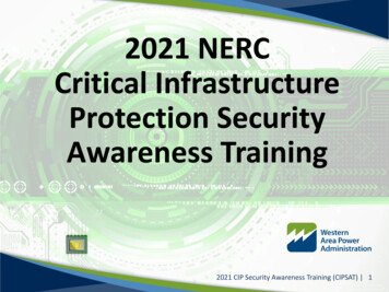
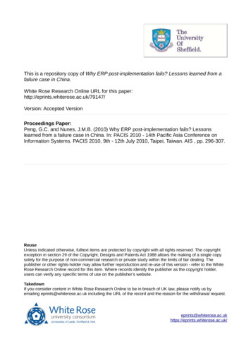
Lesson LearnedProtracted Fault in a Transmission SubstationPrimary Interest GroupsTransmission Operators (TOPs)Transmission Owners (TOs)Problem StatementElectronic communications equipment utilized to transmit and receive information from the remoteterminals of a transmission line automatically shut down within milliseconds when a bus fault occurred atone terminal of the line. Neither the primary nor the back-up relay protection cleared the fault. The faultcontinued for over four minutes.DetailsA single-phase-to-ground fault occurred on an instrument voltagetransformer connected to the bus section that serves as thetransmission line’s terminal at Substation 1. The instrument voltagetransformer was a capacitive coupling voltage transformer (CCVT)1,comprised of a stack of coupling capacitors that form a voltagedivider that supplies approximately 5 kV to a small potential devicethat in turn steps down the voltage to 120 volts for utilization bymetering and back-up protective relaying. (See Figure 1). Thisinstrument voltage transformer had exhibited low, out-of-toleranceoutput prior to the event. Low output voltage is often thought to bea benign condition for coupling capacitor devices.2 The output tometering and back-up relaying had been temporarily isolated priorto the event to preclude false readings and avoid the risk of relaymisoperation, but the coupling capacitors remained connected3 tothe transmission bus.Communications equipment shut down at the substation where thefault occurred because of an electrical transient associated with thefault. The communication channels carried information utilized bythe line differential relaying essential to the protection of the lineand the bus sections at the line terminals.Figure 1: Typical CCVT1CCVTs are one of the 14 common substation equipment types listed in the NERC Event Analysis’ “Addendum for Events with Failed StationEquipment” for capturing failure modes and mechanisms in reported events.2 When capacitors begin to fail in a CCVT, it is usually by shorting out of individual capacitor packs in the string. If packs short out above theCCVT’s “low voltage tap,” the output voltage rises. If packs below the ‘low voltage tap’ short out, the output voltage would lower. In eithercase, there would be increased voltage stress across all the remaining capacitors in the string, accelerating their failure. As long as the stringremains energized, this leads to a continuous sequence of shorting packs out and eventual catastrophic failure. Monitoring the output for “stairsteps” can warn of a developing failure.3 The isolated output meant the condition of the capacitor string could not be monitored for the developing failure. It would have been betterto remove power from the capacitors too. The difficulty of getting clearances for equipment that is expected to be “always on” contributed toleaving the equipment in this state for a long duration.RELIABILITY RESILIENCE SECURITY
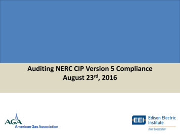
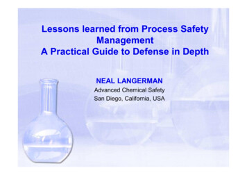
The transient, coupled to a 125-volt DC battery supply circuit in the substation by induction, activated ashutdown feature built into the electronic switching power supplies of the communications equipment.This feature was intended to protect the communications equipment against internal overloads on itsprinted circuit boards, chassis, and internal wiring. However, in this case, there was no internal overload.The shutdown feature misoperated in the presence of the transient because it carried an electrical orelectronic signature similar to a bona fide overload condition within the communications equipment.The instantaneous loss of communications prevented the line differential relaying from properly detectingthe fault, so it blocked tripping by design. Stand-alone back-up relaying at the local substation where thefault occurred was temporarily out of service due to a problem with an instrument voltage transformercircuit. Stand-alone back-up relaying at one of the remote substations was slow in detecting the fault forseveral reasons, listed here: The line includes a series reactor with significant impedance (seven times more than the lineimpedance itself) for limiting fault current so as not to exceed interrupting capability of the circuitbreakers. The impedance posed a challenge to setting the distance relay elements to ensure theydid not over-reach to the next substation. The ratio of the impedance presented by the transmission line to a phase fault versus a ground faultis very different from the ratio presented by the series reactor. This results in the combined circuit(line and reactor) having an overall impedance that is non-homogeneous, posing another challengeto setting the distance relay elements. The fault evolved from a single-phase-to-ground fault to a three-phase-fault, then to a doublephase-to-ground fault, and finally back to a single-phase-to-ground fault. This evolution resulted inground and phase distance elements alternately picking up and dropping out during the course ofthe event.Figure 2 depicts the three-terminal transmission line involved in the event. One of the two redundant linesof primary line differential relaying is shown in a simplified format, including the communication equipmentat two of the terminals. The third terminal is not included in the diagram for the sake of simplicity.Lesson Learned: Protracted Fault in a Transmission Substation2
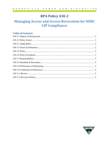
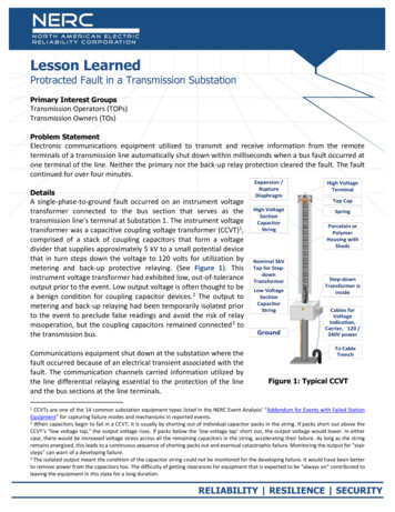
Figure 2: One Line Diagram of Faulted Circuit and Line Differential ProtectionThe fault was not cleared by either the primary or the back-up relay protection. It was determined fromdigital event files within the protective relays that communications between the relays for this circuitceased simultaneously with the inception of the fault. Specifically, all four multiplexers associated with theline protection at Substation 1 had automatically shut down. The multiplexers are integral to thecommunications. They convert signals from the relays to a format suitable for transmitting over the digitaltelephone networks. Figure 3 depicts the redundant double-triangular arrangement of the communicationchannels – Routes 1 and 2 – spanning all three terminals of the transmission line. It can be seen that eachprotective relay utilizes two multiplexers, one to connect to each of the two other substations.The multiplexers were powered down even though their power switches were found in the ON position,and the 125 volt dc supplies from substation batteries were not interrupted. Each of the four multiplexershas two internal and independent electronic power supplies for the sake of redundancy. All eight internalelectronic power supplies shut down automatically, which is the proximate cause of the loss of digitalcommunications.NOTE: If only one of the eight power supplies in the four multiplexers at Substation 1 had not shut down,the fault would have been cleared in normal high-speed fashion because the signals to and from Substation1 would be exchanged with either Substation 2 or 3 as long as one route of communication remainedbetween Substation 1 and either of the other two substations and then retransmitted between Substations2 and 3, completing the triangular communications.Lesson Learned: Protracted Fault in a Transmission Substation3
After the event, all eight of the power supplies were able to be restarted simply by manually cycling theirpower switches from ON to OFF and back to ON again. The multiplexers then resumed functioning, andnormal communications were restored. There was no visible or functional damage to the multiplexerswhatsoever. Neither the impacted electric utility nor the manufacturer is aware of this issue occurring priorto this event. The multiplexer equipment has a good track record of performance in the industry worldwide for many years.Figure 3: Redundant Communications for Three-Terminal LineThe shutdown was the result of activation of a control scheme on each power supply’s printed circuit boardthat was intended to protect the power supply from overloading in the event of a short circuit within themultiplexer chassis or on any of its printed circuit boards, including those serving the communicationsfunctions. The scheme, when activated, inputs a signal into the integrated circuit chip that controls theswitching cycle of the power electronics that simply stops the switching and holds it off until the powersupply is manually restarted by toggling its ON-OFF rocker switch.By design, the primary current differential relaying inhibited tripping when communications were lost. Theloss of digital communication was simultaneous with the fault. Inhibiting tripping when communicationsare lost is necessary to prevent false tripping because the differential relays are unable to compare theLesson Learned: Protracted Fault in a Transmission Substation4
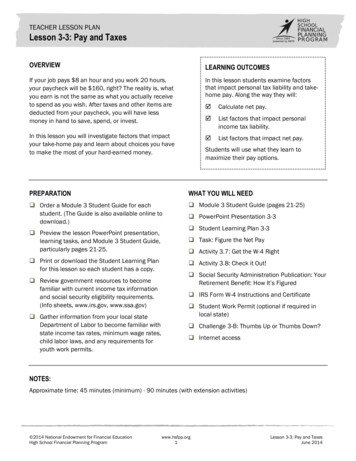
current flowing into the transmission line at one end to the current flowing out at the other end withoutcommunications.As previously mentioned, an electrical transient generated by the fault on the Substation 1 bus section wascoupled into the 125 volt dc battery supply circuit to the multiplexers. The exact mechanism of this couplingfrom an AC transmission fault into a dc supply circuit is not known. It was recognized, however, that the dcsupply circuit was routed a considerable distance ( 1000 feet) in substation trenches and cable trays sharedwith ac control wiring. It is typical the shielding is interrupted when cables enter and leave junction boxes.This offers a possible path for coupling by induction.Another area that is typically of concern when problematic transients are generated by switching surges,lightning, or faults is substation grounding. Post-event testing revealed that the continuity between twoadjacent ground grids in the affected area–one where the multiplexers reside and the other where the faultoccurred–was less than desirable. This may have resulted in a more severe electrical transient beingimposed on the multiplexer.Post-event testing succeeded in recreating the shutdown scenario by selective switching on the powersystem. During this testing, a transient was captured that was subsequently reproduced by a signalgenerator and applied to the multiplexer power supplies, resulting in their shutdown. The electricalsignature of this applied test transient waveform was different from those specified in the IEEE C37.90standard for surge withstand capability. The standard includes both an oscillatory and fast transient testwaveform. The test transient that resulted in the shutdown of the multiplexers was lower in amplitude andhad a slower rate-of-rise than the IEEE waveforms but was of a longer duration. Thus, it fell outside thebounds of the standard. The multiplexer was designed to withstand the IEEE waveforms, and successfullypassed when subjected to these waveforms.Figures 4–7 show some of the damage that resulted from the event.Lesson Learned: Protracted Fault in a Transmission Substation5
Figure 4: Failed C Phase CCPDFigure 5: Damaged B Phase CCPDFigure 6: Remnants of Bus InsulatorsLesson Learned: Protracted Fault in a Transmission Substation6
Figure 7: Exterior of Relay House Singed by Protracted FaultCorrective ActionsAll equipment damaged at Substation 1 during the fault was replaced. This included the instrument voltagetransformer for the stand-alone back-up relaying that had been temporarily out of service.The routing of the 125 volt DC supply feeds to the multiplexers that shut down during the event atSubstation 1 has been significantly shortened, bypassing the long runs in control wiring trenches across thesubstation yard.The ground grids at the affected substations have been reinforced.An extent of condition review was conducted system-wide to identify locations where the type ofmultiplexer that shut down during the event is utilized for both the first and second line protective relaying.A fast-track effort was then embarked on to replace the power supplies in all of these multiplexers (twoeach) with power supplies that had been modified by the manufacturer to disable the shutdown scheme.This was based on the underlying premise that it is preferable to sacrifice the power supplies within amultiplexer that develops an internal overload than to incorrectly shut down the unit and consequentlydisable a communications channel vital to the protective relaying. In addition, for all of the transmissionlines associated with the substations involved in the event, the multiplexers on one of the two lines ofLesson Learned: Protracted Fault in a Transmission Substation7
communication for every transmission line were replaced with new units of a different design and from adifferent manufacturer for the sake of diversifying the communications.Going forward, all new and upgraded installations will utilize relays and communications equipment(multiplexers included) from different manufacturers for the first and second line protective relaying. Thisdiversity of suppliers for redundant equipment is fundamental to the philosophy and design basis forprotective relaying systems on transmission facilities.Modifications of the stand-alone back-up relaying ensure coverage of the entire circuit with adequatemargin so that the whole line, including any intermediary equipment, is sufficiently protected.Lesson Learned Equipment that is out of service for maintenance, repairs, or replacement should be completelyisolated. The maintenance, repair, or replacement work should then be conducted as quickly aspossible to minimize potential compromises to system reliability. Control wiring routing and shielding should be designed to minimize the possibility of the couplingof transients between adjacent circuits. The functions served by protective relaying systems (including associated communications) arecritical to the reliability of the transmission system. These functions, therefore, must have priorityover schemes intended to monitor and react to problems internal to the individual component
02.04.2020 · transformer was a capacitive coupling voltage transformer (CCVT)1, . a benign condition for coupling capacitor devices.2 The output to metering and back-up relaying had been temporarily isolated prior to the event to preclude false readings and avoid the risk of relay misoperation, but the coupling capacitors remained connected3 to the transmission bus. Communications