Transcription
P-TS7User ManualRevision AC o p y r i g h t 2 0 1 5 E le c tr o n i c T h e a t r e C o n t r o l s , I n c .All Rights reserved.P r o d u c t in f o r m a t i on a n d s p e c i f i c a t i o n s s u bj e c t t o c h a n g e .P a r t N u m b e r : 7184M1220 R e v AR e le a s ed : 2 0 1 5 - 0 4
Table of ContentsIntroduction . . . . . . . . . . . . . . . . . . . . . . . . . . 1Touchscreen Specifications. . . . . . . . . . . . . . . . . . . . . . . . . . . . .1Warnings and Notice Conventions . . . . . . . . . . . . . . . . . . . . . . .1Contacting ETC . . . . . . . . . . . . . . . . . . . . . . . . . . . . . . . . . . . . . .2Overview . . . . . . . . . . . . . . . . . . . . . . . . . . . . 3Power and Data Connections . . . . . . . . . . . . . . . . . . . . . . . . . . . . . .3LinkConnect. . . . . . . . . . . . . . . . . . . . . . . . . . . . . . . . . . . . . . . . .3NetConnect . . . . . . . . . . . . . . . . . . . . . . . . . . . . . . . . . . . . . . . . .3Touchscreen Inputs, Outputs and Indicators . . . . . . . . . . . . . . . . . . .4Ports . . . . . . . . . . . . . . . . . . . . . . . . . . . . . . . . . . . . . . . . . . . . . .4Buttons and Indicator LEDs . . . . . . . . . . . . . . . . . . . . . . . . . . . . .4Status . . . . . . . . . . . . . . . . . . . . . . . . . . . . . . . . . . . . . . . . . . . . . . .5LON . . . . . . . . . . . . . . . . . . . . . . . . . . . . . . . . . . . . . . . . . . . . . . . . .5NET . . . . . . . . . . . . . . . . . . . . . . . . . . . . . . . . . . . . . . . . . . . . . . . . .5ControlDesigner Software . . . . . . . . . . . . . . . . . . . . . . . . . . . . . . . . .5Setup Menu . . . . . . . . . . . . . . . . . . . . . . . . . 7Setup Menu . . . . . . . . . . . . . . . . . . . . . . . . . . . . . . . . . . . . . . . . . . . .8About tab . . . . . . . . . . . . . . . . . . . . . . . . . . . . . . . . . . . . . . . . . . .8Screen tab . . . . . . . . . . . . . . . . . . . . . . . . . . . . . . . . . . . . . . . . . .9Calibrate Touchscreen . . . . . . . . . . . . . . . . . . . . . . . . . . . . . . . . .10Sound tab . . . . . . . . . . . . . . . . . . . . . . . . . . . . . . . . . . . . . . . . .10Comms tab . . . . . . . . . . . . . . . . . . . . . . . . . . . . . . . . . . . . . . . .11Config tab . . . . . . . . . . . . . . . . . . . . . . . . . . . . . . . . . . . . . . . . .11Protected Features and Tabs . . . . . . . . . . . . . . . . . . . . . . . . . . . . . .12Timed Events. . . . . . . . . . . . . . . . . . . . . . . . . . . . . . . . . . . . . . .12Add Event . . . . . . . . . . . . . . . . . . . . . . . . . . . . . . . . . . . . . . . . . . .13Files tab . . . . . . . . . . . . . . . . . . . . . . . . . . . . . . . . . . . . . . . . . .16Saving and Loading Configuration Files . . . . . . . . . . . . . . . . . . . .17Network tab . . . . . . . . . . . . . . . . . . . . . . . . . . . . . . . . . . . . . . . .17IP Addressing . . . . . . . . . . . . . . . . . . . . . . . . . . . . . . . . . . . . . . . .18System tab. . . . . . . . . . . . . . . . . . . . . . . . . . . . . . . . . . . . . . . . .18Reload Firmware . . . . . . . . . . . . . . . . . . . . . . . . . . . . . . . . . . . . . .19Reset to Defaults . . . . . . . . . . . . . . . . . . . . . . . . . . . . . . . . . . . . .19Cleaning the Display . . . . . . . . . . . . . . . . . . 20E T C , Un iso n a nd Pa r ad ig m ar e e it h er re gi st er e d t ra de mar ks or tr a de mar ks o f E le ct r on ic T he at r e C on tr o ls , I nc .i n t he Uni te d Sta t es an d ot he r co un tr i es. Al l ot h er t r ad ema r ks, b ot h mar k ed an d no t mar k ed, ar e t he pr o pe rt y of th ei rr e spe ct iv e owne r s.i
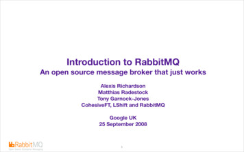
IntroductionWelcome to the Paradigm P-TS7 touchscreen user manual. This document applies to allP-TS7 touchscreen models including wall mount, rack mount, and portable units (Ethernetor LON).This document is intended specifically for instruction using the P-TS7 software. Referencethe related P-TS7 Installation or Setup Guide for information on hardware installation andsetup.P-TS7 Wall Mount TouchscreenP-TS7-P Portable TouchscreenThe wall mount touchscreen is also available with a locking cover or in a rack mount panel.Touchscreen SpecificationsThe P-TS7 is a high resolution color touchscreen for use with the Paradigm ArchitecturalControl Processor (P-ACP). It features a 7" (17.8cm) WVGA display with 800x480 pixelresolution utilizing 24-bit color depth and a 10:6 aspect ratio.Warnings and Notice ConventionsThese symbols are used in ETC documentation to alert you to danger or importantinformation:Note:Notes are helpful hints and information that is supplemental to the main text.CAUTION:A Caution statement indicates situations where there may be undefined orunwanted consequences of an action, potential for data loss or an equipmentproblem.WARNING:A Warning statement indicates situations where damage may occur, peoplemay be harmed, or there are serious or dangerous consequences of anaction.WARNING:RISK OF ELECTRIC SHOCK! This warning statement indicates situationswhere there is a risk of electric shock.Introduction1
Contacting ETCIf you are having difficulties with your P-TS7, your most convenient resources are thereferences given in this user guide. To search more widely, try the ETC website atwww.etcconnect.com. If none of these resources is sufficient, contact ETC TechnicalServices directly at one of the offices identified below. Emergency service is available fromall ETC offices outside of normal business hours. When calling for help, please have thefollowing information handy: Your location and job name. A complete list of ETC product including model and serial numbers if available. A list of other installed components in your system (Unison , other consoles, etc.).AmericasElectronic Theatre Controls Inc.Technical Services Department3031 Pleasant View RoadMiddleton, WI 53562800-775-4382 (USA, toll-free) 1-608 831-4116service@etcconnect.comAsiaUnited KingdomElectronic Theatre Controls Ltd.Technical Services Department26-28 Victoria Industrial EstateVictoria Road,London W3 6UU England 44 (0)20 8896 1000service@etceurope.comGermanyElectronic Theatre Controls Asia, Ltd.Technical Services DepartmentRoom 1801, 18/FTower 1, Phase 1 Enterprise Square9 Sheung Yuet RoadKowloon Bay, Kowloon, Hong Kong 852 2799 1220service@etcasia.comElectronic Theatre Controls GmbHTechnical Services DepartmentOhmstrasse 383607 Holzkirchen, Germany 49 (80 24) 47 00-0techserv-hoki@etcconnect.comPlease email comments about this manual to: TechComm@etcconnect.com2Paradigm P-TS7 User Manual
OverviewPower and Data ConnectionsP-TS7 Wall Mount and Rack Mount touchscreen stations are designed to connect to theParadigm Control system using either LinkConnect or NetConnect for power and data.Note:The ground connection to the Wall Mount and Rack Mount P-TS7 is providedthrough the RJ11 connection, regardless of the data connection type,LinkConnect or NetConnect.A P-TS7-P portable touchscreen is designed to connect to the Paradigm Control systemusing only Portable LinkConnect; a Unison Heritage Portable Connector (UH1RS) stationwired using LinkConnect is required.A P-TS7-PE portable touchscreen connects directly to the lighting network and usesNetConnect for power and data.LinkConnectLinkConnect uses Echelon LonTalk with LinkPower to connect between the P-TS7 andthe Paradigm Architectural Control Processor.The P-TS7 Wall Mount, when connected over LinkConnect, uses three watts of power at24 Vdc.Reference the related touchscreen installation guide for details on hardware installationand setup.NetConnectNetConnect uses Power over Ethernet (PoE 802.3af) communications to connect betweenthe P-TS7/P-TS7-PE and the host Paradigm rack enclosure.Reference the related touchscreen installation guide for details on hardware installation,wiring requirements and setup.Overview3
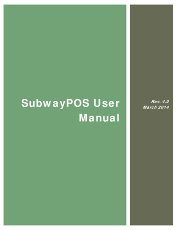
Touchscreen Inputs, Outputs and IndicatorsEach model of the touchscreen has an I/O panel that includes an USB port, SD card slot,and a selection of indicators and service pins. The indicator and service pin selections varydepending on the model of touchscreen.The P-TS7-P/PE portable I/O panel is located behind a door on the bottom of the unit.ResetModeAux Act SvcSvc DataStatusResetModeLONAux ActSvc SvcDataStatusLONResetModePoEStatusActDataNETThe P-TS7 Wall Mount and Rack Mount I/O panel is located on the bottom of the unit,viewable only when the LCD is in the service position.To move the touchscreen into a serviceposition, lift up from the bottom of the unit andpull outward to a slight angle. The I/O panel islocated on the bottom of the unit.Ports USB port - This connection is used for local upload or download of configuration andtheme files and system upgrades. The USB connection supports all USB keys thatrequire 250mA of power or less. Secure Digital (SD) card slot - This connection is used for local upload and downloadof configuration and theme files and system upgrades. The SD card slot supportsstandard SD cards up to 2GB.Buttons and Indicator LEDsEach of the buttons and indicators on the touchscreen I/O panel are labeled and groupedaccording to its relationship and function.For example, the section labeled with “Status” include all buttons and indicators that relatespecifically to the touchscreens function and features including software reset, setup menuaccess, and power source.Buttons and indicators that relate specifically to LinkConnect data use are labeled in the“LON” section and others that relate specifically to NetConnect data use are labeled in the“NET” section.4Paradigm P-TS7 User Manual
Note:Availability of buttons and indicators varies according to the touchscreen model.Status “Reset” button - when pressed, resets the LCD software causing a reboot and servicepin message to the connected processor. “Mode” button - press once for “Setup menu”. Press and hold four seconds tocalibrate the touchscreen. “PoE” LED- illuminates solid when Power over Ethernet is present (NetConnect only). “Aux” LED - illuminates solid when the touchscreen is powered (LinkConnect only). “Act” LED - reserved for future development.LON “Svc” pin button - sends a “service pin” message when pressed, which sends thestation Neuron ID to the connected processor. This provides the same function as theon screen [Service Pin] button found in the Setup Menu. “Svc” LED - illuminates when a service pin command has been sent to the processor. “Data” LED - illuminates (flashing) to indicate transmission of data packets when thetouchscreen is connected to a processor using LinkConnect.NET “Link” LED - indicates a valid network connection is present to the touchscreen usingNetConnect. This indicates connection to any Ethernet device (such as a switch). “Data” LED - indicates by flashing LED when data is transmitted over NetConnect.This indicates connection to any network device (such as a switch).ControlDesigner SoftwareParadigm ControlDesigner software is used to create graphical layouts and pagenavigation for P-TS7 stations. These graphical layouts and page navigations are alsoknown as the touchscreen configuration file.The P-TS7 supports configuration files that are uploaded from the connected ParadigmArchitectural Control Processor (P-ACP) or loaded directly to the touchscreen usingremovable media, such as a USB key or Secure Digital (SD) card.Overview5
6Paradigm P-TS7 User Manual
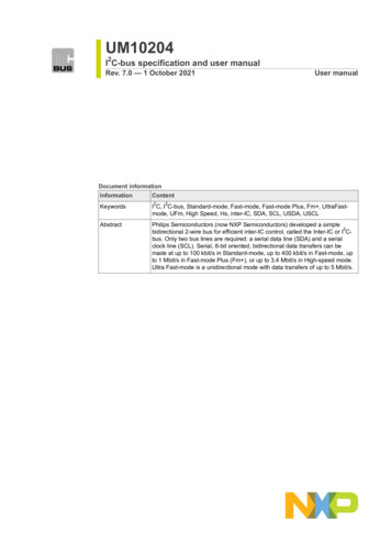
Setup MenuOn initial power-up, with no ControlDesigner configuration installed or when thetouchscreen is not bound/connected to a processor, the touchscreen displays the defaultsplash page; which includes the ETC logo and two buttons; [Setup] and [Service Pin].Pressing the [Setup] button accesses the Setup Menu where setup options and technicalinformation are displayed. Pressing the [Service Pin] button issues a binding request tothe Paradigm Architectural Control Processor over the control network. When thetouchscreen is bound/connected to a processor, a configuration file will begin to load.Setup Menu7
Setup MenuPressing the [Setup] button on the default page displays the About tab of the touchscreensetup menu. Alternatively, you can access the setup menu by pressing the “Mode” pin onthe touchscreen I/O panel. See “Touchscreen Inputs, Outputs and Indicators” on page 4.Each tab of the setup menu displays a footer of buttons including [Service Pin], [Ok] and[Cancel].About tabThe About tab displays read-only information pertaining to the touchscreen including; MAC Address: a unique identifier assigned to the touchscreen by ETC foridentification over the Paradigm network. IP Address: the current network IP address assigned to the touchscreen. This numbercan be modified from the Network tab. Neuron Id: a station specific unique hardware address that is permanent to thetouchscreen. This ID is used by the Paradigm Architectural Control Processor to bind/associate (bind) stations within the LightDesigner configuration. Bootloader: the bootloader software version. Firmware: the firmware version loaded onto the touchscreen. Firmware can beupdated, reference System tab, page 18 for instructions.Note:Note:8The firmware version in the touchscreen must be compatible with the firmwareversion in the Paradigm Architectural Control Processor (P-ACP) for the twodevices to communicate. Memory Usage: The “Memory Usage” section displays the “Total” memory available,the memory “Used” and the available memory that is “Free” for use. Boot Reason: the last action that caused the touchscreen to boot. Reasons for rebootcould be due to a [Reset] button press on the touchscreen I/O panel, power loss, etc. Watchdog: displays the status of the Watchdog tool.Watchdog is a service that monitors touchscreen activity and will automaticallyreboot the device in the event it would suffer a crash or lockup. Watchdog shouldbe “enabled” unless instructed otherwise by ETC Technical Services.Paradigm P-TS7 User Manual
Screen tabThe “Screen” tab provides user settings for the touchscreen including: Backlight Level: a level bar is provided to set the relative brightness of thetouchscreen backlight. By default, the level is set to full.Note:Setup MenuWhen the light sensor is “On”, the backlight level sets the maximum level ofbrightness. Backlight Timeout: sets the length of inactivity time before the backlight fades to itsbacklight timeout level. This is separate from any configuration related InactivityTimeout settings. Backlight Timeout “Level”: the intensity level the backlight will fade to when its“Backlight Timeout” has been reached. This level can be set to either “Off” or “Dim”. Light Sensor: allows the touchscreen to determine an appropriate Backlight Levelbased on ambient light in the space. The internal light sensor measures the ambientlight and adjusts the backlight proportionally based on the established backlight levelsettings. By default, the light sensor is “Off”. Proximity Sensor: when enabled (“On” which is default), proximity allows thetouchscreen to detect a user’s presence as he/she approaches the touchscreen foruse. When proximity is detected, the touchscreen automatically turns on the backlightand displays the inactivity page that was configured in ControlDesigner. Proximity isonly supported on the wall mount P-TS7. The proximity sensor uses active IR to determine proximity to the touchscreen. Thesensor has a sensing distance of approximately one foot with a field angle of 15degrees. If the sensor registers any moving or stationary objects within this range, it will“wake” the station from its sleeping state and reset the backlight timeout and the9
station inactivity timer as set in ControlDesigner.Note:Be aware of stationary objects (such as rack doors) that remain within the sensingrange as it may interfere with the function of the sensor. In these applications, it isbest practice to disable the Proximity Sensor.The proximity sensor is looking for reflected IR; therefore any IR devices (such asalarms or listening assistance systems) within a range of the proximity sensor mayprevent the system from sleeping or displaying an inactivity page.Calibr ate TouchscreenThe “Screen” tab provides a [Calibrate Touchscreen] button that will launch a tool usedto recalibrate the touchscreen.Note:You can also press and hold the [Mode] button (located on the I/O panel of thetouchscreen) for four seconds to launch the calibration display.If pressing on the screen causes unintended results (such as the press registeringelsewhere on the screen), calibration may be required.To calibrate the touchscreen:Step 1:Press [Calibrate Touchscreen]. The screen will clear and a “ ” symbol will bedisplayed.Step 2:Press as close to the center of the “ ” as possible. The symbol will move to a newlocation on the screen.Step 3:Press the “ ” in each new location. A total of five locations will be tested.Step 4:When all five coordinates have been calibrated, press [Close] to return to thepreviously displayed page.If you are unsatisfied with the calibration results, press [Recalibrate] to start the calibrationagain or press [Clear] to clear your settings.S o u n d ta bThe “Sound” tab provides a volume control for the master volume level of the touchscreen’sbuilt-in speaker.10Paradigm P-TS7 User Manual
Comms tabThe “Comms” tab provides read-only information about the Paradigm Architectural ControlProcessor (P-ACP) to which the touchscreen is connected over the Paradigm controlnetwork. Server Name: this is the name of the P-ACP Connection Type: this is the type of connection that is made to the P-ACP. Optionsinclude “Ethernet” which is NetConnect, or “Lon” which is LinkConnect.Note:This is useful when troubleshooting your communication connection between theP-TS7 and your Paradigm control system.When a P-TS7 is connected by NetConnect, the IP address of the P-ACP willdisplay as the “Server Address”.A Portable LON P-TS7 will indicate the Connector ID of the Portable ConnectorStation (UH1RS) it is connected to.Config tabThe “Config” tab displays the project information that was provided in ControlDesigner.Project information can only be modified in ControlDesigner.Setup Menu11
Protected Features and TabsThe “Files”, “Network” and “System” tabs as well as the “Timed Events” feature on the“Config” tab are protected by passcode and should be used only by trained personnel.Typically these displays are accessed only during system commissioning. Pressing any ofthe tab names will display a keypad for passcode entry.Note:Enter your four digit passcode to access these menus. These protectedtabs should be accessed only by trained personnel.Timed EventsThe “Timed Events” button on the Config tab is a passcode protected feature that allowsusers to add and edit Timed Events. Press the [Timed Events] button on the Config tab, andenter the passcode to begin. All created timed events will display in the “Timed EventSetup” menu. From this menu you can add new events, or delete or edit existing events inthe list.Note:12ControlDesigner provides a page navigation action to reach a Timed Eventconfiguration directly. Use this feature to provide access for end users who wishto edit Timed Events.Paradigm P-TS7 User Manual
Adding a new event and editing an event are similar in process.Add EventSetup MenuStep 1:Press the [Add] button, a “New Timed Event” configurator will display.Step 2:Specify the “Start Time”. Pressing the default [Time of Day] button displays a listof available start times including; “Time of Day”, “Sunrise”, and “Sunset”. Pressto select the option. Depending on the selection, additional options may display: If “Time of Day” is selected, additional selection for a “Start Time” is required. If “Sunrise” or “Sunset” are selected, additional selection for an “Offset” isrequired. An offset is specified as an additive (press the [ ] button) ornegative (press the [-] button) hour and minutes setting from theastronomical time.13
14Step 3:Specify the “End Time”. The options for “End Time” are similar to the “Start Time”except “Duration” is now an option. When “Duration” is the selected “End Time”,you will also be required to specify the hours and minutes the event should runfrom its start time.Step 4:If an override has been created for the Timed Event, select the override from theoptions. For more information regarding overrides, please reference theParadigm LightDesigner online help system or contact ETC Technical Services.Step 5:Press [Next] to specify the Recurrence settings of the Timed Event.Step 6:Select the “Recurrence Type” from the options available.Paradigm P-TS7 User Manual
Additional settings are provided depending on the “Recurrence Type”selected. For example, if “Weekly” is selected, the following options display -Step 7:Press [Next] then select the drop down selection located next to “Start Action” todisplay available options.Step 8:Press to select the option from the list. Notice the ability to scroll to more optionsusing the scroll bar on the right. Depending on the selection, more options maydisplay for setting on the “Start Action” page. Complete the options as required.Step 9:Press [Next] then select the drop down selection located next to “End Action” todisplay available options.Step 10: Press to select the option from the list. Notice the ability to scroll to more optionsusing the scroll bar on the right. Depending on the selection, more options maydisplay for setting on the “End Action” page. Complete the options as required.Setup Menu15
Files tabThe “Files” tab allows you to view, modify, and delete the configuration and theme files thatare currently loaded on the touchscreen. As well, you are provided access for uploadingand downloading the configuration and theme files from/to removable media such as an SDcard or USB key. See “Ports” on page 4.Note:If the P-TS7 is already associated with a Paradigm Architectural ControlProcessor (P-ACP), it will automatically begin retrieving its LCD configuration filewhen powered.Standard ETC provided themes are loaded for you at ETC and will displaybeneath the “Themes” directory.16Paradigm P-TS7 User Manual
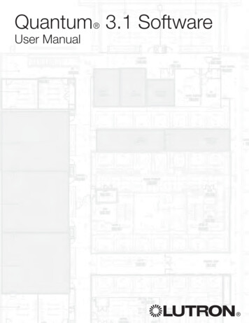
Saving and L oading Conf iguration FilesSaving and loading configuration and theme files is simple.Step 1:To begin, you must have an USB key or SD card (your choice) inserted into theport receptacle of the touchscreen.Step 2:Select either [Config] or [Theme] (whichever file type you want to transfer).Step 3:If saving a file to removable media select the file from the list and press [Saveto]. If loading a file from removable media, press [Load From].Step 4:Choose the removable media (SD or USB) you are transferring to/from.Step 5:Navigate the file structure of the removable media to select the location you aresaving to/loading from. To return to a previous directory in the removable media,press the [Up] button. Press [Ok] to set the directory location.Note:Multiple files can be selected for upload or download by simply touching to selecteach file. When a file with the same name exists at the save to location or if italready exists on the touchscreen when loading from removable media, you willbe prompted to either [Cancel] the action or [Overwrite] the existing conflictingfile.Network tab15011.1The “Network” tab provides access to view and edit the network address settings for thetouchscreen. The touchscreen ships with the defaults displayed in the image above.Setup Menu17
IP AddressingTwo “IP Addressing” modes are available for use with the touchscreen; Manual andAutomatic. Manual Mode - in manual address mode the IP address and settings are userconfigured. To change any portion of the address, simply touch inside the field you wishto modify. A numeric keypad will display for edit of the selected field. Make themodifications to the selected field then select another field for edit as necessary.Pressing [Ok] saves your changes, exits the Setup Menu and returns the display toyour default page (or inactivity page as defined in your configuration).Note:When multiple touchscreens are installed into your system, they must each havea unique IP address. For example, 10.101.15.101, 10.101.15.102, etc. DuplicateIP addresses will cause system communication problems. Automatic Mode - in automatic mode, the touchscreen is configured to obtain an IPaddress and other network settings automatically from a connected DCHP server. Thetouchscreen will display the current settings provided from the connected DHCP serverbut the settings are not user editable. If no DHCP server is present, the touchscreenwill assign itself a link-local address in the default 169.254.x.x range. Pressing [Ok]saves your “Setup menu” changes, exits the Setup Menu and returns the display toyour default page (or inactivity page as defined in your configuration), automatic modeis not recommended for most applications.System tabThe read only-information displayed on this tab is of interest only to ETC Technical Servicesfor troubleshooting and has minimal use to an end user. System - the system information relates specifically to the touchscreen hardware. Co-Processor - the co-processor provides portable specific functionality. These willappear as “N/A” for wall mount touchscreens. 18Board Revision - the touchscreen hardware revision level.Bootloader: the touchscreen co-processor bootloader version.Paradigm P-TS7 User Manual
Firmware: the touchscreen co-processor firmware version.Reload FirmwareNote:Firmware should only be upgraded by a trained ETC Technician, or wheninstructed by ETC Technical Services.The [Reload Firmware] button is provided as a tool to load new firmware. Firmware isloaded to the touchscreen from removable media.Note:The touchscreen firmware file is stored in the LightDesigner installation directoryfirmware folder (the file is titled “firmware.pts”). Save the file to the root directoryof a USB or SD card for loading onto the P-TS7.Step 1:Insert the USB key or SD card, with the firmware files saved, into the port on thetouchscreen.Step 2:Press the [Reload Firmware] button.Step 3:Select the removable media (USB or SD) from the recognized installed media.Note:A message may display when the firmware file is not recognized on the selectedremovable media. Check that the firmware file was saved to the root directory ofthe selected media, then try the reload process again.Step 4:Note:Select the “firmware.pts” file from the list. As the firmware file completes loading,the touchscreen will reboot.When updating your P-TS7 firmware, you may also need to update your ParadigmArchitectural Control Processor firmware to remain compatible.Reset to DefaultsRestores factory defaults to the settings on the “Screen”, “Sound”, and “Network” pages.Setup Menu19
Cleaning the DisplayUse a dry micro fibre or lint-free cloth to clean any finger prints and oils from the LCD. Donot use any chemical or water-base solution as they will damage the display.20Paradigm P-TS7 User Manual
Corporate Headquarters 3031 Pleasant View Road, P.O. Box 620979, Middleton, Wisconsin 53562-0979 USA Tel 608 831 4116 Fax 608 836 1736London, UK Unit 26-28, Victoria Industrial Estate, Victoria Road, London W3 6UU, UK Tel 44 (0)20 8896 1000 Fax 44 (0)20 8896 2000Rome, IT Via Pieve Torina, 48, 00156 Rome, Italy Tel 39 (06) 32 111 683 Fax 44 (0) 20 8752 8486Holzkirchen, DE Ohmstrasse 3, 83607 Holzkirchen, Germany Tel 49 (80 24) 47 00-0 Fax 49 (80 24) 47 00-3 00Hong Kong Rm 1801, 18/F, Tower 1 Phase 1, Enterprise Square, 9 Sheung Yuet Road, Kowloon Bay, Kowloon, Hong Kong Tel 852 2799 1220 Fax 852 2799 9325Service: (Americas) service@etcconnect.com (UK) service@etceurope.com (DE) techserv-hoki@etcconnect.com (Asia) service@etcasia.comWeb: www.etcconnect.com Copyright 2015 ETC. All Rights Reserved. Product information and specifications subject to change.7184M1220 Rev A Released 2015-04
A P-TS7-P portable touchscreen is designed to connect to the Paradigm Control system using only Portable LinkConnect; a Unison Heritage Portable Connector (UH1RS) station wired using LinkConnect is required. A P-TS7-PE portable touchscreen connects directly to the lighting ne