Transcription
UM102042I C-bus specification and user manualRev. 7.0 — 1 October 2021User manualDocument informationInformationContentKeywordsI C, I C-bus, Standard-mode, Fast-mode, Fast-mode Plus, Fm , UltraFastmode, UFm, High Speed, Hs, inter-IC, SDA, SCL, USDA, USCLAbstractPhilips Semiconductors (now NXP Semiconductors) developed a simple2bidirectional 2-wire bus for efficient inter-IC control, called the Inter-IC or I Cbus. Only two bus lines are required: a serial data line (SDA) and a serialclock line (SCL). Serial, 8-bit oriented, bidirectional data transfers can bemade at up to 100 kbit/s in Standard-mode, up to 400 kbit/s in Fast-mode, upto 1 Mbit/s in Fast-mode Plus (Fm ), or up to 3.4 Mbit/s in High-speed mode.Ultra Fast-mode is a unidirectional mode with data transfers of up to 5 Mbit/s.22
NXP Semiconductors2UM10204I C-bus specification and user manualTable 1. Revision historyRevDateDescriptionv.720211001User manual; seventh releaseModifications: Updated Table 5 Updated the terms "master/slave" to "controller/target" throughout to align with MIPI I3Cspecification and NXP's Inclusive Language Project Added Section 9v.6User manual; sixth release20140404Modifications: Figure 41 updated (recalculated) Figure 42 updated (recalculated)v.520121009User manual; fifth releasev.420120213User manual Rev. 4v.320070619Many of today’s applications require longer buses and/or faster speeds. Fast-mode Plus wasintroduced to meet this need by increasing drive strength by as much as 10 and increasing thedata rate to 1 Mbit/s while maintaining downward compatibility to Fast-mode and Standard-modespeeds and software commands.v2.12000Version 2.1 of the I C-bus specificationv2.01998The I C-bus has become a de facto world standard that is now implemented in over 1000 differentICs and licensed to more than 50 companies. Many of today’s applications, however, require higher2bus speeds and lower supply voltages. This updated version of the I C-bus specification meetsthose requirements.v1.01992Version 1.0 of the I C-bus specificationOriginal1982first releaseUM10204User manual222All information provided in this document is subject to legal disclaimers.Rev. 7.0 — 1 October 2021 NXP B.V. 2021. All rights reserved.2 / 62
NXP Semiconductors2UM10204I C-bus specification and user manual1Introduction2The I C-bus is a de facto world standard that is now implemented in over 1000 different2ICs manufactured by more than 50 companies. Additionally, the versatile I C-bus isused in various control architectures such as System Management Bus (SMBus), PowerManagement Bus (PMBus), Intelligent Platform Management Interface (IPMI), DisplayData Channel (DDC) and Advanced Telecom Computing Architecture (ATCA).2This document assists device and system designers to understand how the I C-busworks and implement a working application. Various operating modes are described. It2contains a comprehensive introduction to the I C-bus data transfer, handshaking and busarbitration schemes. Detailed sections cover the timing and electrical specifications for2the I C-bus in each of its operating modes.2Designers of I C-compatible chips should use this document as a reference and ensurethat new devices meet all limits specified in this document. Designers of systems that2include I C devices should review this document and also refer to individual componentdata sheets.2Readers looking to develop I C based solutions may also be interested in I3C, introducedby the MIPI Alliance in 2017, with NXP's involvement and contributions. MIPI I3C offers2backward compatibility with I C, increased speed and low power consumption, and aroyalty-free version is available for implementers. More information is included at the endof this document in Section 9.22I C-bus featuresIn consumer electronics, telecommunications and industrial electronics, there are oftenmany similarities between seemingly unrelated designs. For example, nearly everysystem includes: Some intelligent control, usually a single-chip microcontroller General-purpose circuits like LCD and LED drivers, remote I/O ports, RAM, EEPROM,real-time clocks or A/D and D/A converters Application-oriented circuits such as digital tuning and signal processing circuits forradio and video systems, temperature sensors, and smart cardsTo exploit these similarities to the benefit of both systems designers and equipmentmanufacturers, as well as to maximize hardware efficiency and circuit simplicity, PhilipsSemiconductors (now NXP Semiconductors) developed a simple bidirectional 2-wire22bus for efficient inter-IC control. This bus is called the Inter IC or I C-bus. All I C-buscompatible devices incorporate an on-chip interface which allows them to communicate2directly with each other via the I C-bus. This design concept solves the many interfacingproblems encountered when designing digital control circuits.2Here are some of the features of the I C-bus: Only two bus lines are required; a serial data line (SDA) and a serial clock line (SCL). Each device connected to the bus is software addressable by a unique address andsimple controller/target relationships exist at all times; controllers can operate ascontroller-transmitters or as controller-receivers. It is a true multi-controller bus including collision detection and arbitration to preventdata corruption if two or more controllers simultaneously initiate data transfer.UM10204User manualAll information provided in this document is subject to legal disclaimers.Rev. 7.0 — 1 October 2021 NXP B.V. 2021. All rights reserved.3 / 62
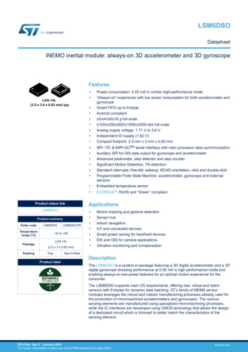
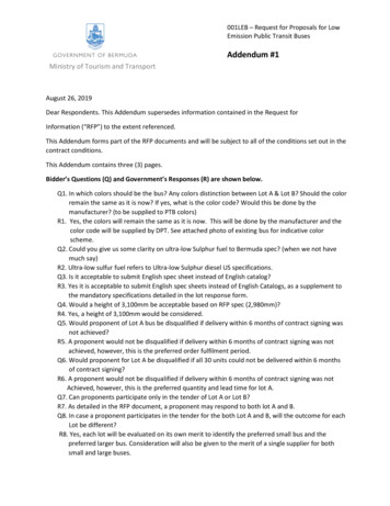
UM10204NXP Semiconductors2I C-bus specification and user manual Serial, 8-bit oriented, bidirectional data transfers can be made at up to 100 kbit/s in theStandard-mode, up to 400 kbit/s in the Fast-mode, up to 1 Mbit/s in Fast-mode Plus, orup to 3.4 Mbit/s in the High-speed mode. Serial, 8-bit oriented, unidirectional data transfers up to 5 Mbit/s in Ultra Fast-mode On-chip filtering rejects spikes on the bus data line to preserve data integrity. The number of ICs that can be connected to the same bus is limited only by amaximum bus capacitance. More capacitance may be allowed under some conditions.Refer to Section 7.2.2Figure 1 shows an example of I C-bus applications.I2 CA/D or D/AConvertersI2 CGeneral PurposeI/O ExpandersI2CLED ControllersI2CDIP rsVDD0I2C Portvia HW orBit BangingVDD2PCA9541I2 CController Selector/DemuxI2 CMultiplexersand SwitchesI2CSerial EEPROMsMCUsVDD1I2CBus Controllers8I2CReal Time Clock/CalendarsLCD Drivers(with I2C)MCUsI2CTemperatureSensorsVDD3Bridges(with I2C)SPIUARTUSB002aac8582Figure 1. Example of I C-bus applications2.1 Designer benefits2I C-bus compatible ICs allow a system design to progress rapidly directly from afunctional block diagram to a prototype. Moreover, since they ‘clip’ directly onto the2I C-bus without any additional external interfacing, they allow a prototype system to bemodified or upgraded simply by ‘clipping’ or ‘unclipping’ ICs to or from the bus.2Here are some of the features of I C-bus compatible ICs that are particularly attractive todesigners: Functional blocks on the block diagram correspond with the actual ICs; designsproceed rapidly from block diagram to final schematic.2 No need to design bus interfaces because the I C-bus interface is already integratedon-chip.UM10204User manualAll information provided in this document is subject to legal disclaimers.Rev. 7.0 — 1 October 2021 NXP B.V. 2021. All rights reserved.4 / 62
UM10204NXP Semiconductors2I C-bus specification and user manual Integrated addressing and data-transfer protocol allow systems to be completelysoftware-defined. The same IC types can often be used in many different applications. Design-time reduces as designers quickly become familiar with the frequently used2functional blocks represented by I C-bus compatible ICs. ICs can be added to or removed from a system without affecting any other circuits onthe bus. Fault diagnosis and debugging are simple; malfunctions can be immediately traced. Software development time can be reduced by assembling a library of reusablesoftware modules.2In addition to these advantages, the CMOS ICs in the I C-bus compatible range offerdesigners special features which are particularly attractive for portable equipment andbattery-backed systems.They all have: Extremely low current consumptionHigh noise immunityWide supply voltage rangeWide operating temperature range.2.2 Manufacturer benefits2I C-bus compatible ICs not only assist designers, they also give a wide range of benefitsto equipment manufacturers because:2 The simple 2-wire serial I C-bus minimizes interconnections so ICs have fewer pinsand there are not so many PCB tracks; result — smaller and less expensive PCBs.2 The completely integrated I C-bus protocol eliminates the need for address decodersand other ‘glue logic’.2 The multi-controller capability of the I C-bus allows rapid testing and alignment of enduser equipment via external connections to an assembly line.2 The availability of I C-bus compatible ICs in various leadless packages reduces spacerequirements even more.2These are just some of the benefits. In addition, I C-bus compatible ICs increasesystem design flexibility by allowing simple construction of equipment variants and easyupgrading to keep designs up-to-date. In this way, an entire family of equipment can bedeveloped around a basic model. Upgrades for new equipment, or enhanced-featuremodels (that is, extended memory, remote control, etc.) can then be produced simply byclipping the appropriate ICs onto the bus. If a larger ROM is needed, it is simply a matterof selecting a microcontroller with a larger ROM from our comprehensive range. As newICs supersede older ones, it is easy to add new features to equipment or to increaseits performance by simply unclipping the outdated IC from the bus and clipping on itssuccessor.2.3 IC designer benefitsDesigners of microcontrollers are frequently under pressure to conserve output pins.2The I C protocol allows connection of a wide variety of peripherals without the need forseparate addressing or chip enable signals. Additionally, a microcontroller that includes2an I C interface is more successful in the marketplace due to the wide variety of existingperipheral devices available.UM10204User manualAll information provided in this document is subject to legal disclaimers.Rev. 7.0 — 1 October 2021 NXP B.V. 2021. All rights reserved.5 / 62
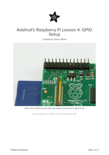
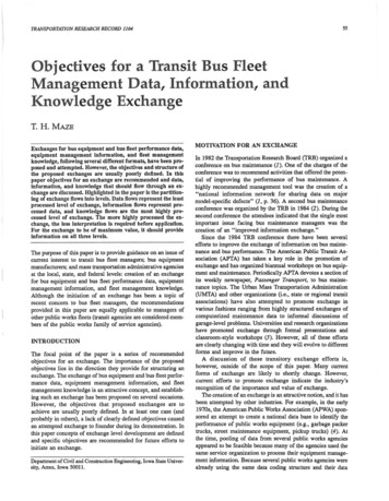
UM10204NXP Semiconductors2I C-bus specification and user manual32The I C-bus protocol23.1 Standard-mode, Fast-mode and Fast-mode Plus I C-bus protocolsTwo wires, serial data (SDA) and serial clock (SCL), carry information between thedevices connected to the bus. Each device is recognized by a unique address (whether itis a microcontroller, LCD driver, memory or keyboard interface) and can operate as eithera transmitter or receiver, depending on the function of the device. An LCD driver maybe only a receiver, whereas a memory can both receive and transmit data. In addition totransmitters and receivers, devices can also be considered as controllers or targets whenperforming data transfers (see Table 2). A controller is the device which initiates a datatransfer on the bus and generates the clock signals to permit that transfer. At that time,any device addressed is considered a target.2Table 2. Definition of I C-bus terminologyTermDescriptionTransmitterthe device which sends data to the busReceiverthe device which receives data from the busControllerthe device which initiates a transfer, generates clock signals andterminates a transferTargetthe device addressed by a controllerMulti-controllermore than one controller can attempt to control the bus at the same timewithout corrupting the messageArbitrationprocedure to ensure that, if more than one controller simultaneously triesto control the bus, only one is allowed to do so and the winning messageis not corruptedSynchronizationprocedure to synchronize the clock signals of two or more devices2The I C-bus is a multi-controller bus. This means that more than one device capable ofcontrolling the bus can be connected to it. As controllers are usually microcontrollers, letus consider the case of a data transfer between two microcontrollers connected to the2I C-bus (see Figure 2).MICRO CONTROLLERALCDDRIVERSTATICRAM OREEPROMSDASCLGATEARRAYMICRO CONTROLLERBADCmbc6452Figure 2. Example of an I C-bus configuration using two microcontrollersThis example highlights the controller-target and receiver-transmitter relationships found2on the I C-bus. Note that these relationships are not permanent, but only depend on thedirection of data transfer at that time. The transfer of data would proceed as follows:UM10204User manualAll information provided in this document is subject to legal disclaimers.Rev. 7.0 — 1 October 2021 NXP B.V. 2021. All rights reserved.6 / 62
UM10204NXP Semiconductors2I C-bus specification and user manual1. Suppose microcontroller A wants to send information to microcontroller B: microcontroller A (controller), addresses microcontroller B (target) microcontroller A (controller-transmitter), sends data to microcontroller B (targetreceiver) microcontroller A terminates the transfer.2. If microcontroller A wants to receive information from microcontroller B: microcontroller A (controller) addresses microcontroller B (target) microcontroller A (controller-receiver) receives data from microcontroller B (targettransmitter) microcontroller A terminates the transfer.Even in this case, the controller (microcontroller A) generates the timing and terminatesthe transfer.2The possibility of connecting more than one microcontroller to the I C-bus means thatmore than one controller could try to initiate a data transfer at the same time. To avoidthe chaos that might ensue from such an event, an arbitration procedure has been2developed. This procedure relies on the wired-AND connection of all I C interfaces to the2I C-bus.If two or more controllers try to put information onto the bus, the first to produce a ‘one’when the other produces a ‘zero’ loses the arbitration. The clock signals during arbitrationare a synchronized combination of the clocks generated by the controllers usingthe wired-AND connection to the SCL line (for more detailed information concerningarbitration see Section 3.1.8).2Generation of clock signals on the I C-bus is always the responsibility of controllerdevices; each controller generates its own clock signals when transferring data on thebus. Bus clock signals from a controller can only be altered when they are stretched bya slow target device holding down the clock line or by another controller when arbitrationoccurs.2Table 3 summarizes the use of mandatory and optional portions of the I C-busspecification and which system configurations use them.2Table 3. Applicability of I C-bus protocol featuresM mandatory; O optional; n/a not applicable.FeatureUser manual[1]Single controllerMulti-controllerTargetSTART conditionMMMSTOP bitrationn/aMn/a[2]O7-bit target addressMMM10-bit target addressOOOGeneral Call addressOOOSoftware ResetOOn/aO[2]Clock stretchingSTART byteUM10204ConfigurationOO[3]All information provided in this document is subject to legal disclaimers.Rev. 7.0 — 1 October 2021On/a NXP B.V. 2021. All rights reserved.7 / 62
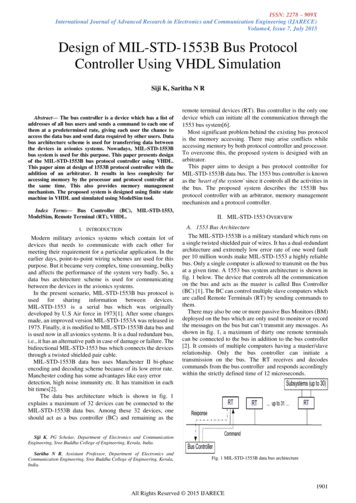
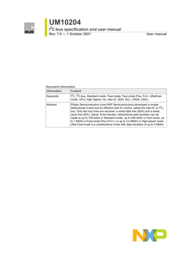
UM10204NXP Semiconductors2I C-bus specification and user manual2Table 3. Applicability of I C-bus protocol features.continuedM mandatory; O optional; n/a not applicable.FeatureConfigurationDevice ID[1][2][3][1]Single controllerMulti-controllerTargetn/an/aOAlso refers to a controller acting as a target.Clock stretching is a feature of some targets. If no targets in a system can stretch the clock (hold SCL LOW), thecontroller need not be designed to handle this procedure.‘Bit banging’ (software emulation) multi-controller systems should consider a START byte. See Section 3.1.15.3.1.1 SDA and SCL signalsBoth SDA and SCL are bidirectional lines, connected to a positive supply voltage viaa current-source or pull-up resistor (see Figure 3). When the bus is free, both lines areHIGH. The output stages of devices connected to the bus must have an open-drain or2open-collector to perform the wired-AND function. Data on the I C-bus can be transferredat rates of up to 100 kbit/s in the Standard-mode, up to 400 kbit/s in the Fast-mode,up to 1 Mbit/s in Fast-mode Plus, or up to 3.4 Mbit/s in the High-speed mode. The buscapacitance limits the number of interfaces connected to the bus.For a single controller application, the controller’s SCL output can be a push-pull driverdesign if there are no devices on the bus which would stretch the clock.VDD1 5 V 10 2, VDD3 are device-dependent (for example, 12 V).Figure 3. Devices with various supply voltages sharing the same bus3.1.2 SDA and SCL logic levelsDue to the variety of different technology devices (CMOS, NMOS, bipolar) that can be2connected to the I C-bus, the levels of the logical ‘0’ (LOW) and ‘1’ (HIGH) are not fixedand depend on the associated level of VDD. Input reference levels are set as 30 % and 70% of VDD; VIL is 0.3VDD and VIH is 0.7VDD. See Figure 38, timing diagram. Some legacydevice input levels were fixed at VIL 1.5 V and VIH 3.0 V, but all new devices requirethis 30 %/70 % specification. See Section 6 for electrical specifications.3.1.3 Data validityThe data on the SDA line must be stable during the HIGH period of the clock. The HIGHor LOW state of the data line can only change when the clock signal on the SCL line isLOW (see Figure 4). One clock pulse is generated for each data bit transferred.UM10204User manualAll information provided in this document is subject to legal disclaimers.Rev. 7.0 — 1 October 2021 NXP B.V. 2021. All rights reserved.8 / 62
NXP Semiconductors2UM10204I C-bus specification and user manualSDASCLdata linestable;data validchangeof dataallowedmba6072Figure 4. Bit transfer on the I C-bus3.1.4 START and STOP conditionsAll transactions begin with a START (S) and are terminated by a STOP (P) (seeFigure 5). A HIGH to LOW transition on the SDA line while SCL is HIGH defines aSTART condition. A LOW to HIGH transition on the SDA line while SCL is HIGH definesa STOP condition.SDASCLSPSTART conditionSTOP conditionmba608Figure 5. START and STOP conditionsSTART and STOP conditions are always generated by the controller. The bus isconsidered to be busy after the START condition. The bus is considered to be free againa certain time after the STOP condition. This bus free situation is specified in Section 6.The bus stays busy if a repeated START (Sr) is generated instead of a STOP condition.In this respect, the START (S) and repeated START (Sr) conditions are functionallyidentical. For the remainder of this document, therefore, the S symbol is used as ageneric term to represent both the START and repeated START conditions, unless Sr isparticularly relevant.Detection of START and STOP conditions by devices connected to the bus is easy ifthey incorporate the necessary interfacing hardware. However, microcontrollers with nosuch interface have to sample the SDA line at least twice per clock period to sense thetransition.3.1.5 Byte formatEvery byte put on the SDA line must be eight bits long. The number of bytes that can betransmitted per transfer is unrestricted. Each byte must be followed by an Acknowledgebit. Data is transferred with the Most Significant Bit (MSB) first (see Figure 6). If a targetcannot receive or transmit another complete byte of data until it has performed someother function, for example servicing an internal interrupt, it can hold the clock line SCLLOW to force the controller into a wait state. Data transfer then continues when the targetis ready for another byte of data and releases clock line SCL.UM10204User manualAll information provided in this document is subject to legal disclaimers.Rev. 7.0 — 1 October 2021 NXP B.V. 2021. All rights reserved.9 / 62
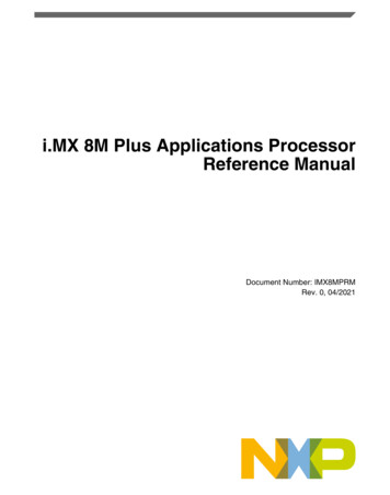
UM10204NXP Semiconductors2I C-bus specification and user manualPSDAacknowledgmentsignal from targetMSBSCLS or Sr12789acknowledgmentsignal from receiver123 to 8ACKSTART orrepeated STARTconditionbyte complete,interrupt within target9ACKclock line held LOWwhile interrupts are servicedSrSr or PSTOP orrepeated STARTcondition002aac8612Figure 6. Data transfer on the I C-bus3.1.6 Acknowledge (ACK) and Not Acknowledge (NACK)The acknowledge takes place after every byte. The acknowledge bit allows the receiverto signal the transmitter that the byte was successfully received and another byte maybe sent. The controller generates all clock pulses, including the acknowledge ninth clockpulse.The Acknowledge signal is defined as follows: the transmitter releases the SDA lineduring the acknowledge clock pulse so the receiver can pull the SDA line LOW and itremains stable LOW during the HIGH period of this clock pulse (see Figure 4). Set-upand hold times (specified in Section 6) must also be taken into account.When SDA remains HIGH during this ninth clock pulse, this is defined as the NotAcknowledge signal. The controller can then generate either a STOP condition to abortthe transfer, or a repeated START condition to start a new transfer. There are fiveconditions that lead to the generation of a NACK:1. No receiver is present on the bus with the transmitted address so there is no device torespond with an acknowledge.2. The receiver is unable to receive or transmit because it is performing some real-timefunction and is not ready to start communication with the controller.3. During the transfer, the receiver gets data or commands that it does not understand.4. During the transfer, the receiver cannot receive any more data bytes.5. A controller-receiver must signal the end of the transfer to the target transmitter.3.1.7 Clock synchronizationTwo controllers can begin transmitting on a free bus at the same time and there mustbe a method for deciding which takes control of the bus and complete its transmission.This is done by clock synchronization and arbitration. In single controller systems, clocksynchronization and arbitration are not needed.2Clock synchronization is performed using the wired-AND connection of I C interfacesto the SCL line. This means that a HIGH to LOW transition on the SCL line causes thecontrollers concerned to start counting off their LOW period and, once a controller clockhas gone LOW, it holds the SCL line in that state until the clock HIGH state is reached(see Figure 7). However, if another clock is still within its LOW period, the LOW to HIGHtransition of this clock may not change the state of the SCL line. The SCL line is thereforeheld LOW by the controller with the longest LOW period. Controllers with shorter LOWperiods enter a HIGH wait-state during this time.UM10204User manualAll information provided in this document is subject to legal disclaimers.Rev. 7.0 — 1 October 2021 NXP B.V. 2021. All rights reserved.10 / 62
UM10204NXP Semiconductors2I C-bus specification and user manualwaitstatestart countingHIGH periodCLK1CLK2counterresetSCLmbc632Figure 7. Clock synchronization during the arbitration procedureWhen all controllers concerned have counted off their LOW period, the clock line isreleased and goes HIGH. There is then no difference between the controller clocks andthe state of the SCL line, and all the controllers start counting their HIGH periods. Thefirst controller to complete its HIGH period pulls the SCL line LOW again.In this way, a synchronized SCL clock is generated with its LOW period determined bythe controller with the longest clock LOW period, and its HIGH period determined by theone with the shortest clock HIGH period.3.1.8 ArbitrationArbitration, like synchronization, refers to a portion of the protocol required only if morethan one controller is used in the system. Targets are not involved in the arbitrationprocedure. A controller may start a transfer only if the bus is free. Two controllers maygenerate a START condition within the minimum hold time (tHD;STA) of the STARTcondition which results in a valid START condition on the bus. Arbitration is then requiredto determine which controller will complete its transmission.Arbitration proceeds bit by bit. During every bit, while SCL is HIGH, each controllerchecks to see if the SDA level matches what it has sent. This process may take manybits. Two controllers can actually complete an entire transaction without error, as longas the transmissions are identical. The first time a controller tries to send a HIGH, butdetects that the SDA level is LOW, the controller knows that it has lost the arbitration andturns off its SDA output driver. The other controller goes on to complete its transaction.No information is lost during the arbitration process. A controller that loses the arbitrationcan generate clock pulses until the end of the byte in which it loses the arbitration andmust restart its transaction when the bus is free.If a controller also incorporates a target function and it loses arbitration during theaddressing stage, it is possible that the winning controller is trying to address it. Thelosing controller must therefore switch over immediately to its target mode.Figure 8 shows the arbitration procedure for two controllers. More may be involveddepending on how many controllers are connected to the bus. The moment there is adifference between the internal data level of the controller generating DATA1 and theactual level on the SDA line, the DATA1 output is switched off. This does not affect thedata transfer initiated by the winning controller.UM10204User manualAll information provided in this document is subject to legal disclaimers.Rev. 7.0 — 1 October 2021 NXP B.V. 2021. All rights reserved.11 / 62
NXP Semiconductors2UM10204I C-bus specification and user manualcontroller 1 loses arbitrationDATA 1 SDADATA 1DATA 2SDASCLSmsc609Figure 8. Arbitration procedure of two controllers2Since control of the I C-bus is decided solely on the address and data sent by competingcontrollers, there is no central controller, nor any order of priority on the bus.There is an undefined condition if the arbitration procedure is still in progress at themoment when one controller sends a repeated START or a STOP condition while theother controller is still sending data. In other words, the following combinations result inan undefined condition: Controller 1 sends a repeated START condition and controller 2 sends a data bit. Controller 1 sends a STOP condition and controller 2 sends a data bit. Controller 1 sends a repeated START condition and controller 2 sends a STOPcondition.3.1.9 Clock stretchingClock stretching pauses a transaction by holding the SCL line LOW. The transactioncannot continue until the line is released HIGH again. Clock stretching is optional and infact, most target devices do not include an SCL driver so they are unable to stretch theclock.On the byte level, a device may be able to receive bytes of data at a fast rate, but needsmore time to store a received byte or prepare another byte to be transmitted. Targets canthen hold the SCL line LOW after reception and acknowledgment of a byte to force thecontroller into a wait state until the target is ready for the next byte transfer in a type ofhandshake procedure (see Figure 7).On the bit level, a device such as a microcontroller with or without limited hardware for2the I C-bus, can slow down the bus clock by extending each clock LOW period. Thespeed of any controller is adapted to the internal operating rate of this device.In Hs-mode, this handshake feature can only be used on byte level (see Section 5.3.2).3.1.10 The target address and R/W bitData transfers follow the format shown in Figure 9. After the START condition (S), atarget address is sent. This address is seven bits long followed by an eighth bit which isa data direction bit (R/W) — a ‘zero’ indicates a transmission (WRITE), a ‘one’ indicatesa request for data (READ) (refer to Figure 10). A data transfer is always terminated byUM10204User manualAll information provided in this document is subject to legal disclaimers.Rev. 7.0 — 1 October 2021 NXP B.V. 2021. All rights reserved.12 / 62
UM10204NXP Semiconductors2I C-bus specification and user manuala STOP condition (P) generated by the controller. However, if a controller still wishes tocommunicate on the bus, it can generate a repeated START condition (Sr) and addressanother target without first generating a STOP condition. Various combinations of read/write formats are then possible within such a ESSR/WACKDATAACKDATAACKSTOPconditionmbc604Figure 9. A complete data transferMSBLSBR/Wtarget addressmbc608Figure 10. The first byte after the START procedurePossible data transfer formats are: Controller-transmitter transmits to target-receiver. The transfer direction is not changed(see Figure 11). The target receiver acknowledges each byte. Controller reads target immediately after first byte (see Figure 12). At the moment ofthe first acknowledge, the controller-transmitter becomes a controller-receiver and thetarget-receiver becomes a target-transmitter. This first acknowledge is still generatedby the target. The controller generates subsequent acknowledges. The STOP conditionis generated by the controller, which sends a not-acknowledge (A) just before theSTOP condition. Combined format (see Figure 13). During a change of direction within a transfer,the START condition and the target address are both repeated, but with the R/W bitreversed. If a controller-receiver sends a repeated START condition, it sends a notacknowledge (A) just before the repeated START condition.Notes:1. Combined formats can be used, for example, to control a serial memory. T
v.6 20140404 User manual; sixth release Modifications: Figure 41 updated (recalculated) Figure 42 updated (recalculated) v.5 20121009 User manual; fifth release v.4 20120213 User manual Rev. 4 v.3 20070619 Many of today's applications require longer buses and/or faster speeds. Fast-mode Plus was