Transcription
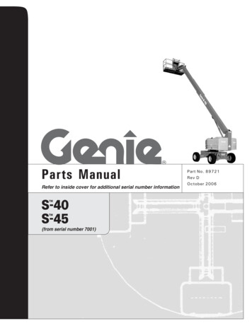
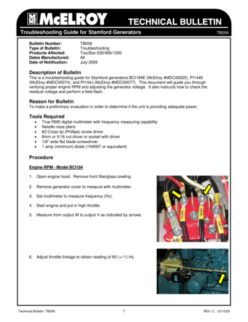
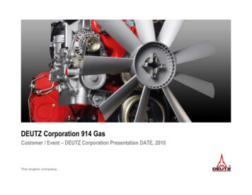
ENGINE & WORKING PRINCIPLESA heat engine is a machine, which converts heat energy into mechanical energy. Thecombustion of fuel such as coal, petrol, diesel generates heat. This heat is supplied to aworking substance at high temperature. By the expansion of this substance in suitablemachines, heat energy is converted into useful work. Heat engines can be further divided intotwo types:(i)External combustion and(ii)Internal combustion.In a steam engine the combustion of fuel takes place outside the engine and the steamthus formed is used to run the engine. Thus, it is known as external combustion engine. In thecase of internal combustion engine, the combustion of fuel takes place inside the enginecylinder itself.The IC engine can be further classified as: (i) stationary or mobile, (ii) horizontal or vertical and (iii) low, medium or high speed. The two distinct types of IC engines used for eithermobile or stationary operations are: (i) diesel and (ii) carburettor.Heat EngineExternal CombustionInternal CombustionSteam EngineReciprocatingCI EngineTwo StrokeWankelRotary GasTurbineSI EngineFour StrokeTwo StrokeFour StrokeChart 1. Types of Heat EnginesSpark Ignition (Carburettor Type) IC EngineIn this engine liquid fuel is atomised, vaporized and mixed with air in correct proportionbefore being taken to the engine cylinder through the intake manifolds. The ignition of themixture is caused by an electric spark and is known as spark ignition.Compression Ignition (Diesel Type) IC EngineIn this only the liquid fuel is injected in the cylinder under high pressure.CONSTRUCTIONAL FEATURES OF IC ENGINE:The cross section of IC engine is shown in Fig. 1. A brief description of these parts is givenbelow.Cylinder:The cylinder of an IC engine constitutes the basic and supporting portion of the engine powerunit. Its major function is to provide space in which the piston can operate to draw in the fuelmixture or air (depending upon spark ignition or compression ignition), compress it, allow itto expand and thus generate power. The cylinder is usually made of high-grade cast iron. Insome cases, to give greater strength and wear resistance with less weight, chromium, nickeland molybdenum are added to the cast iron.
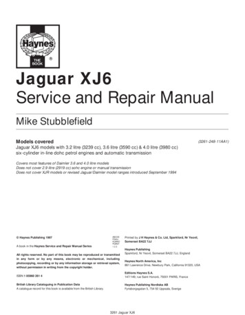
Piston:The piston of an engine is the first part to begin movement and to transmit power to thecrankshaft as a result of the pressure and energy generated by the combustion of the fuel. Thepiston is closed at one end and open on the other end to permit direct attachment of theconnecting rod and its free action.Fig. 1 Cross-section of a diesel engineThe materials used for pistons are grey cast iron, cast steel and aluminium alloy. However,the modern trend is to use only aluminium alloy pistons in the tractor engine.Piston Rings:These are made of cast iron on account of their ability to retain bearing qualities and elasticityindefinitely. The primary function of the piston rings is to retain compression and at the sametime reduce the cylinder wall and piston wall contact area to a minimum, thus reducingfriction losses and excessive wear. The other important functions of piston rings are thecontrol of the lubricating oil, cylinder lubrication, and transmission of heat away from thepiston and from the cylinder walls. Piston rings are classed as compression rings and oil ringsdepending on their function and location on the piston.Compression rings are usually plain one-piece rings and are always placed in the groovesnearest the piston head. Oil rings are grooved or slotted and are located either in the lowestgroove above the piston pin or in a groove near the piston skirt. Their function is to controlthe distribution of the lubricating oil to the cylinder and piston surface in order to preventunnecessary or excessive oil consumption ion.AG ENGG. 243 Lecture 32
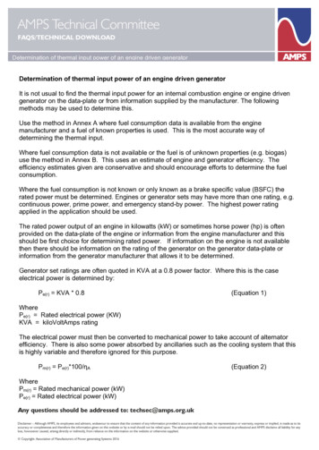
Figure 2. Components of the diesel enginePiston Pin:The connecting rod is connected to the piston through the piston pin. It is made of casehardened alloy steel with precision finish. There are three different methods to connect thepiston to the connecting rod.Connecting Rod:This is the connection between the piston and crankshaft. The end connecting the piston isknown as small end and the other end is known as big end. The big end has two halves of abearing bolted together. The connecting rod is made of drop forged steel and the section is ofthe I-beam type.Crankshaft:This is connected to the piston through the connecting rod and converts the linear motion ofthe piston into the rotational motion of the flywheel. The journals of the crankshaft aresupported on main bearings, housed in the crankcase. Counter-weights and the flywheelbolted to the crankshaft help in the smooth running of the engine.Engine Bearings:The crankshaft and camshaft are supported on anti-friction bearings. These bearings must becapable of with standing high speed, heavy load and high temperatures. Normally, cadmium,silver or copper lead is coated on a steel back to give the above characteristics. For singlecylinder vertical/horizontal engines, the present trend is to use ball bearings in place of mainbearings of the thin shell type.AG ENGG. 243 Lecture 33
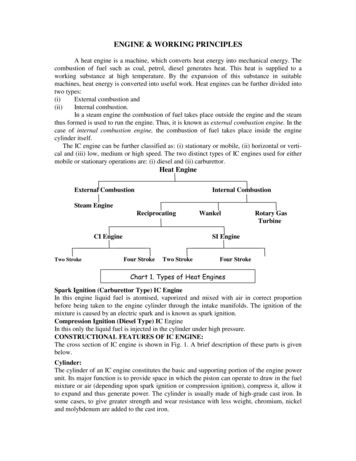
Valves:To allow the air to enter into the cylinder or the exhaust, gases to escape from the cylinder,valves are provided, known as inlet and exhaust valves respectively. The valves are mountedeither on the cylinder head or on the cylinder block.Camshaft:The valves are operated by the action of the camshaft, which has separate cams for the inlet,and exhaust valves. The cam lifts the valve against the pressure of the spring and as soon as itchanges position the spring closes the valve. The cam gets drive through either the gear orsprocket and chain system from the crankshaft. It rotates at half the speed of the camshaft.FlywheelThis is usually made of cast iron and its primary function is to maintain uniform engine speedby carrying the crankshaft through the intervals when it is not receiving power from a piston.The size of the flywheel varies with the number of cylinders and the type and size of theengine. It also helps in balancing rotating masses.Materials used for engine parts:S. No.Name of the PartsCylinderhead1.2.Cylinder liner3.Engine blockPiston4.5.Piston pin6.Connecting rod7.Piston rings8.Connecting rod bearings9.Main bearings10.CrankshaftCamshaft11.12.Timing gears13.Push rods14.Engine valves15.Valve springs16.Manifolds17.Crankcase18.Flywheel19.Studs and bolts20.GasketsMaterials of ConstructionCast iron, Cast AluminiumCast steel, Cast ironCast iron, Cast aluminum, Welded steelCast iron, Aluminium alloyForged steel, Casehardened steel.Forged steel. Aluminium alloy.Cast iron, Pressed steel alloy.Bronze, White metal.White metal, Steel backed Babbitt base.Forged steel, Cast steelForged steel, Cast iron, cast steel,Cast iron, Fiber, Steel forging.Forged steel.Forged steel, Steel, alloy.Carbon spring steel.Cast iron, Cast aluminium.Cast iron, Welded steelCast iron.Carbon steel.Cork, Copper, Asbestos.PRINCIPLES OF OPERATION OF IC ENGINES:FOUR-STROKE CYCLE DIESEL ENGINEIn four-stroke cycle engines there are four strokes completing two revolutions of thecrankshaft. These are respectively, the suction, compression, power and exhaust strokes. InFig. 3, the piston is shown descending on its suction stroke. Only pure air is drawn into thecylinder during this stroke through the inlet valve, whereas, the exhaust valve is closed. Thesevalves can be operated by the cam, push rod and rocker arm. The next stroke is thecompression stroke in which the piston moves up with both the valves remaining closed. TheAG ENGG. 243 Lecture 34
air, which has been drawn into the cylinder during the suction stroke, is progressively compressed as the piston ascends. The compression ratio usually varies from 14:1 to 22:1. Thepressure at the end of the compression stroke ranges from 30 to 45 kg/cm2. As the air isprogressively compressed in the cylinder, its temperature increases, until when near the end ofthe compression stroke, it becomes sufficiently high (650-80O oC) to instantly ignite any fuelthat is injected into the cylinder. When the piston is near the top of its compression stroke, aliquid hydrocarbon fuel, such as diesel oil, is sprayed into the combustion chamber underhigh pressure (140-160 kg/cm2), higher than that existing in the cylinder itself. This fuelthen ignites, being burnt with the oxygen of the highly compressed air.During the fuel injection period, the piston reaches the end of its compression stroke andcommences to return on its third consecutive stroke, viz., power stroke. During this strokethe hot products of combustion consisting chiefly of carbon dioxide, together with thenitrogen left from the compressed air expand, thus forcing the piston downward. This is onlythe working stroke of the cylinder.During the power stroke the pressure falls from its maximum combustion value (47-55kg/cm2), which is usually higher than the greater value of the compression pressure (45kg/cm2), to about 3.5-5 kg/cm2 near the end of the stroke. The exhaust valve then opens,usually a little earlier than when the piston reaches its lowest point of travel. The exhaustgases are swept out on the following upward stroke of the piston. The exhaust valve remainsopen throughout the whole stroke and closes at the top of the stroke.The reciprocating motion of the piston is converted into the rotary motion of the crankshaftby means of a connecting rod and crankshaft. The crankshaft rotates in the main bearings,which are set in the crankcase. The flywheel is fitted on the crankshaft in order to smoothenout the uneven torque that is generated in the reciprocating engine.Fig. 3. Principle of four-stroke engineTWO-STROKE CYCLE DIESEL ENGINE:The cycle of the four-stroke of the piston (the suction, compression, power and exhauststrokes) is completed only in two strokes in the case of a two-stroke engine. The air is drawninto the crankcase due to the suction created by the upward stroke of the piston. On the downstroke of the piston it is compressed in the crankcase, The compression pressure is usuallyvery low, being just sufficient to enable the air to flow into the cylinder through the transferport when the piston reaches near the bottom of its down stroke.The air thus flows into the cylinder, where the piston compresses it as it ascends, till thepiston is nearly at the top of its stroke. The compression pressure is increased sufficientlyAG ENGG. 243 Lecture 35
high to raise the temperature of the air above the self-ignition point of the fuel used. The fuelis injected into the cylinder head just before the completion of the compression stroke andonly for a short period. The burnt gases expand during the next downward stroke of thepiston. These gases escape into the exhaust pipe to the atmosphere through the pistonuncovering the exhaust port.Modern Two-Stroke Cycle Diesel EngineThe crankcase method of air compression is unsatisfactory, as the exhaust gases do not escapethe cylinder during port opening. Also there is a loss of air through the exhaust ports duringthe cylinder charging process. To overcome these disadvantages blowers are used to precompress the air. This pre-compressed air enters the cylinder through the port. An exhaustvalve is also provided which opens mechanically just before the opening of the inlet ports(Fig. 4).Fig. 4 Principle of two-stroke cycle diesel engineFOUR-STROKE SPARK IGNITION ENGINEIn this gasoline is mixed with air, broken up into a mist and partially vaporized in acarburettor (Fig. 5). The mixture is then sucked into the cylinder. There it is compressed bythe upward movement of the piston and is ignited by an electric spark. When the mixture isburned, the resulting heat causes the gases to expand. The expanding gases exert a pressureon the piston (power stroke). The exhaust gases escape in the next upward movement of thepiston. The strokes are similar to those discussed under four-stroke diesel engines. Thevarious temperatures and pressures are shown in Fig. 6. The compression ratio varies from4:1 to 8:1 and the air-fuel mixture from 10:1 to 20:1.Fig. 5. Principle of operation of four-stroke petrol engineAG ENGG. 243 Lecture 36
TWO-STROKE CYCLE PETROL ENGINEThe two-cycle carburettor type engine makes use of an airtight crankcase for partiallycompressing the air-fuel mixture (Fig. 6). As the piston travels down, the mixture previouslydrawn into the crankcase is partially compressed. As the piston nears the bottom of the stroke,it uncovers the exhaust and intake ports. The exhaust flows out, reducing the pressure in thecylinder. When the pressure in the combustion chamber is lower than the pressure in thecrankcase through the port openings to the combustion chamber, the incoming mixture isdeflected upward by a baffle on the piston. As the piston moves up, it compresses the mixtureabove and draws into the crankcase below a new air-fuel mixture.Fig. 6 Principle of operation of two stroke petrol enineThe, two-stroke cycle engine can be easily identified by the air-fuel mixture valve attachedto the crankcase and the exhaust Port located at the bottom of the cylinder.COMPARISON OF CI AND SI ENGINESThe CI engine has the following advantages over the SI engine.1. Reliability of the CI engine is much higher than that of the SI engine. This is because incase of the failure of the battery, ignition or carburettor system, the SI engine cannotoperate, whereas the CI engine, with a separate fuel injector for each cylinder, has lessrisk of failure.2. The distribution of fuel to each cylinder is uniform as each of them has a separateinjector, whereas in the SI engine the distribution of fuel mixture is not uniform, owing tothe design of the single carburettor and the intake manifold.3. Since the servicing period of the fuel injection system of CI engine is longer, itsmaintenance cost is less than that of the SI engine.4. The expansion ratio of the CI engine is higher than that of the SI engine; therefore, theheat loss to the cylinder walls is less in the CI engine than that of the SI engine.Consequently, the cooling system of the CI engine can be of smaller dimensions.5. The torque characteristics of the CI engine are more uniform which results in better topgear performance.6. The CI engine can be switched over from part load to full load soon after starting fromcold, whereas the SI engine requires warming up.7. The fuel (diesel) for the CI engine is cheaper than the fuel (petrol) for SI engine.8. The fire risk in the CI engine is minimised due to the absence of the ignition system.9. On part load, the specific fuel consumption of the CI engine is low.AG ENGG. 243 Lecture 37
ADVANTAGES AND DISADVANTAGES OF TWO-STROKE CYCLE OVERFOUR-STROKE CYCLE ENGINESAdvantages:1)The two-stroke cycle engine gives one working stroke for each revolution of thecrankshaft. Hence theoretically the power developed for the same engine speed andcylinder volume is twice that of the four-stroke cycle engine, which gives only oneworking stroke for every two revolutions of the crankshaft. However, in practice,because of poor scavenging, only 50-60% extra power is developed.2)Due to one working stroke for each revolution of the crankshaft, the turning moment onthe crankshaft is more uniform. Therefore, a two-stroke engine requires a lighterflywheel.3)The two-stroke engine is simpler in construction. The design of its ports is muchsimpler and their maintenance easier than that of the valve mechanism.4)The power required to overcome frictional resistance of the suction and exhaust strokesis saved, resulting in some economy of fuel.5)Owing to the absence of the cam, camshaft, rockers, etc. of the valve mechanism, themechanical efficiency is higher.6)The two-stroke engine gives fewer oscillations.7)For the same power, a two-stroke engine is more compact and requires less space than afour-stroke cycle engine. This makes it more suitable for use in small machines andmotorcycles.8)A two-stroke engine is lighter in weight for the same power and speed especially whenthe crankcase compression is used.9)Due to its simpler design, it requires fewer spare parts.10) A two-stroke cycle engine can be easily reversed if it is of the valve less type.Disadvantages:1.The scavenging being not very efficient in a two-stroke engine, the dilution of thecharges takes place which results in poor thermal efficiency.2.The two-stroke spark ignition engines do not have a separate lubrication system andnormally, lubricating oil is mixed with the fuel. This is not as efrective as thelubrication of a four-stroke engine. Therefore, the parts of the two-stroke engine aresubjected to greater wear and tear.3.In a spark ignition two-stroke engine, some of the fuel passes directly to the exhaust.Hence, the fuel consumption per horsepower is comparatively higher.4.With heavy loads a two-stroke engine gets heated up due to the excessive heat produced. At the same time the running of the engine is riot very smooth at light loads.5.It consumes more lubricating oil because of the greater amount of heat generated.6.Since the ports remain open during the upward stroke, the actual compression startsonly after both the inlet and exhaust ports have been closed. Hence, the compressionratio of this engine is lower than that of a four-stroke engine of the same dimensions.As the efficiency of an engine is directly proportional to its compression ratio, theefficiency of a two-stroke cycle engine is lower than that of a four-stroke cycle engineof the same size.AG ENGG. 243 Lecture 38
AG ENGG. 243 Lecture 3 4 Valves: To allow the air to enter into the cylinder or the exhaust, gases to escape from the cylinder, valves are provided, known as inlet and exhaust valves respectively. The valves are mounted either on the cylinder head or on the cylinder block. Camshaft: The valves are operated by