Transcription
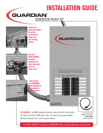
INSTALLATION GUIDEGENERATOR READY KITInstall yourGenerator ReadyKit at theconstructionstage or topre-existinghomes. . .Use yourULTRA SOURCEPortablegenerator forsemi-automaticback-uppower now. . .later installyour GUARDIANHome Standby forfully automaticback-up power!KIT INCLUDES: 100 AMP automatic transfer switch with built-in load center5ft. power cord with 50 AMP plug 30ft., 5ft. and 2ft. pre-wired conduitsExternal connection box 5ft. DC signal harness5ft. Power Cord withNEMA 14-50 plug forULTRA SOURCEPortable GeneratorsFor ULTRA SOURCE Portables & GUARDIAN Home Standby Generator Connections
GENERATOR READY KITPLEASE NOTE:This installation guide is not a substitute for the “Installation and Owner’s Manual” that will befurnished with the GUARDIAN Home Standby Generator you may purchase in the future.Please review the installation procedure again at the time of generator installation. This kit isnot intended for use with the GUARDIAN Liquid-Cooled product line. This kit is not suggestedto be compatible with other generator manufacturer’s products.INTRODUCTIONThank you for purchasing this “Generator Ready” Kit forthe GUARDIAN air-cooled 12kW and 15kW automatic andULTRA SOURCE portable generators. This kit will provideyou the ability to pre-wire your home or business inanticipation of the eventual purchase of a GUARDIAN home standby generator. The majority of the laborinvolved in the generator installation is in the wiring. If youare purchasing for new construction or retro-fitting in anexisting home this kit will save you time and money inprocess. When the time comes to add your GUARDIAN Automatic Home Standby Generator, all you have left is toconnect the unit to the fuel source and install a wiringharness from the generator to the external connectionbox. Then, just add your starting battery and you have theultimate automatic home standby generator system. TheGUARDIAN is on duty.Four commonly used safety symbols accompany theDANGER, WARNING and CAUTION blocks. The type ofinformation each indicates follows: This symbol points out important safety informationthat, if not followed, could endanger personalsafety and/or property of you and others. This symbol points out potential explosion hazard. This symbol points out potential fire hazard. This symbol points out potential electrical shockGenerac cannot possibly anticipate every possiblecircumstance that might involve a hazard. The warnings inthis manual, and on tags and decals affixed to the unit aretherefore, not all-inclusive. If you use a procedure, workmethod or operating technique Generac does notspecifically recommend, you must satisfy yourself that itis safe for you and others. You also must make sure theprocedure, work method or operating technique that youchoose does not render the equipment unsafe. ELECTRICAL HAZARDS Utility power delivers extremely high and dangerousvoltages to the transfer switch as does the standbygenerator when it is in operation. Do not handle any kind of electrical device whilestanding in water, while barefoot, or while hands or feetare wet. DANGEROUS ELECTRICAL SHOCK MAYRESULT. In case of accident caused by electric shock,immediately shut down the source of electrical power. Ifthis is not possible, attempt to free the victim from thelive conductor. AVOID DIRECT CONTACT WITH THEVICTIM. Use a non-conducting implement, such as arope or board, to free the victim from the liveconductor. If the victim is unconscious, apply first aidand get immediate medical help. Never wear jewelry when working on this equipment.Jewelry can conduct electricity resulting in electricshock, or may get caught in moving componentscausing injury.hazard. SAVE THESE INSTRUCTIONS – The manufacturersuggests that these rules for safe operation becopied and posted near the unit’s installation site.Safety should be stressed to all operators andpotential operators of this equipment.1
INSTALLATION GUIDEMAKES A HOME GENERATOR READY!GENERATOR READY KIT4.KIT INCLUDES:1. 50 AMP PLUG ON 5FT. POWER CORD1.2.Use with ULTRA SOURCE portable generator.2. THE EXTERNAL CONNECTION BOXLocated outside the home nearest the incoming gasservice. For connection to generator controls and mainline circuit breaker.3.8.5.3. 5’ PRE-WIRED LIQUID TIGHT CONDUITFor connection between Guardian air-cooled standbygenerator controls and main line circuit breaker toexternal connection box.4. 30’ FLEXIBLE CONDUITPre-wired from the automatic transfer switch with builtin emergency load center for connection to the externalconnection box.5. PRE-WIRED AUTOMATIC TRANSFER SWITCH* AND6. EMERGENCY LOAD CENTER WITH 12 CIRCUITSInstalled within 1 foot of the home’s main distributionpanel. This transfer switch will provide smooth and safetransition between utility and generator power.Eliminates the need to run extension cords.*When usedwith a portable generator the transfer from utility togenerator power will require that some manualconnections are performed by the user. (See page 7)7. 2’ PRE-WIRED CONDUIT FOR EASY CONNECTION TOTHE HOME’S MAIN DISTRIBUTION PANEL8. 5’ DC SIGNAL HARNESSUse with ULTRA SOURCE portable generator.9. 12 UL LISTED WIRE NUTS (not shown)TOOLS REQUIRED:Drill, drill bits, hole saw (type and length will bedetermined by the materials you will be drillingand cutting), open-end wrenches or adjustable wrenches,socket wrenches or nut drivers, standard and Phillipsscrewdrivers, sledge hammer, level, pencil, channel-lockpliers, spade shovel, rake and safety goggles.26.7.ITEMS YOUR MUST PURCHASE:70 AMP double pole circuitbreaker (must be the same typeas in your main electricaldistribution panel)Ground rod with grounding strapCrushed stone or pea gravel(approximately 10-12 cubicfeet)*Black poly-film or othervegetation blocking fabric*Silicone caulkFasteners (to mount connectionbox and automatic transferswitch)Power cord clamp (to secure cordat the external connection box*Only required when a GUARDIAN HomeStandby generator is be installed.
GENERATOR READY KITSite Preparation and Standby Generator Placement1523Crushed Stone or Pea Gravel1.4PLAN THE LOCATION OF YOUR GENERATOR.Drill a 1-3/4” diameter hole through the sheathingand siding with hole saw.NOTE: Do not place the generator directly under awindow.6Select an area outside of your home nearest yourincoming gas service. Determine where thegenerator will be placed outside of the home.Arrange for fuel piping with shut-off valve to be runto this location. Keep in mind that GENERAC recommends placement no closer than 3 feet to anystructure. Local codes may dictate placementfarther from a structure. The 3/4” fuel inlet is located6 inches in from the rear of the unit on the right sideif facing the unit from the front. The fuel inlet is 10.2inches above ground.2.Clear an area 5-1/2 feet by 5 feet of grass andvegetation to a depth of 5 inches. This includes thedistance the generator should be set away from astructure (3 feet) and 6 inches beyond the width andlength of the generator mounting pad (48" L x 24" W).3.Lay black poly-film to cover the area.4.Fill the area to ground level with pea gravel orcrushed stone.5.Drive an 8-foot grounding rod into the ground tograde. Make sure grounding rod and strap are notexposed above ground level. (NEC code applies togrounding method.)6.Drill Hole Through House1-3/4”Diameter Hole7.While adhering to all local electrical codes, route the30 foot conduit along ceiling/floor joists and wallstuds to the location where the conduit will passthrough the wall to the exterior of the house.7Drill Pass Through Hole1-3/4”Diameter HoleDetermine where the flexible conduit will passthrough the house from inside to outside. When youare certain you have clearance on each side of thewall, drill a small pilot hole through the wall to markthe location.3
INSTALLATION GUIDE8Feed Conduit and WiresSiliconeCaulkNOTE: Step 11a and 11b should be performed only if usingthis kit with a Guardian air-cooled automatic standbygenerator (12kW & 15kW) only. Do not install the 5ft. prewired conduit if you are using the ULTRA SOURCE portablegenerator for back up power.11aConnect 5 ft. Conduit to External Connection BoxThe outer diameter of theconduit connector is 1-11/16”8.From the inside of the house, feed the end of the 30foot conduit (INCLUDED and pre-wired from transferswitch) through the wall to outside.Threaded Lock Nut9The outer diameterof the threaded endis 15/16 inches.9.10Remove the threaded lock nut from the conduit coupling.Connect WiresKnockout410. Remove the knock outin the lower right corner ofthe external connection box.From the rear of theconnection box, feed wires& 4-pin plug into box. Slipthe lock nut over wires andplug and tighten securelyonto conduit coupling.Connect the black, red, andwhite wires to matchingwires on threaded lugs andtighten securely. Fasten thegreen ground wire securelyto the lug on the bottom ofthe box. The male end of the4-pin plug is not connectedat this time.11a. Remove the knock out at the bottom left of theexternal connection box. Remove the threaded locknut from the conduit coupling. From the bottom ofthe box, feed the wires and 4-pin plug into the box.Slip the lock nut over wires and plug and tightensecurely onto conduit coupling. Connect wires(Black, red and white) to the lugs with matchingwires and tighten securely. Connect the 4-pin plugtogether with its mating end. Connect the groundwire (green) to the ground lug at the bottom of thebox and tighten to ensure good contact with metalbox.11b. Using appropriatefasteners,mountexternal connectionbox over pre-drilledhole to fully concealthe hole. (Seal aroundthe hole and conduitwith silicone caulkfrom both outsideand inside of house.)11b Mount External Connection Box--- WARNING --The external connection box must be locked to ensuresafety and to discourage tampering.
GENERATOR READY KIT12 Connect 5 ft. Conduit to GeneratorLevel the transfer switch and mark the mountingholes. Drill the appropriate size pilot holes. Mount thetransfer switch to mounting surface with theappropriate fasteners. DANGER: Although you may choose to performelectrical connections yourself, Generac Power Systems,Inc. recommends that a licensed electrician or individualwith complete knowledge of electricity perform theprocedures in sections 14 and 15.12. Access wiring connections for installation of 5 footharness at the generator. To gain access to wiringconnections and the circuit breaker you must removethe cover plate (black) above the control panel whichis attached with 4 fasteners. To aid in removal it maybe necessary to remove the hinge anchor bolt fromthe lower connection point just above the cover plate.Remove the 4 plate fasteners and remove cover plate.Remove the small black cap (covering 1-1/16”diameter hole) from back of enclosure. Removethreaded lock nut from conduit coupling (with 90 elbow) and wires. Feed wires into 1-1/16” diameterhole. Place threaded lock nut over wires and ontoconduit coupling. Tighten securely with screwdriverand hammer to ensure lock nut is tight. Connectpower lead wire (black) to rear inside lug. Connectneutral wire (white) to terminal connection (N). Placeground wire (green) under hold down bolt andtighten ensuring good contact with metal base plate.Connect sensing wires to terminal strip as follows:Blue - N1, Yellow - N2, Brown - 23 and Orange - 194. DANGER: Switch service main circuitbreaker to “off” or open position prior toremoval of cover or removal of any wiring ofthe main electrical distribution panel. Thewires connected to the service main circuit “OFF”breaker remain live or “hot”. Avoid contactwith these wires and the service main circuit breakerconnection lugs.NOTE: Balance must be maintained when moving circuitlocations from main electrical distribution panel toemergency load center. Circuit breaker positionsalternate buss bars vertically. Circuits sharing a neutralwire should either be moved together to adjacentpositions in emergency load center or not moved. If youare unsure of proper procedure or if your installationdiffers from that described in this guide, consult alicensed professional at this time.14a Connection of Emergency Circuits13 Mounting Automatic Transfer Switch1ft.13. Locate automatic transfer switch with built-inemergency load center within one foot of maindistribution panel. The automatic transfer switch canbe located to the left or right of main distributionpanel. Hold transfer switch against the mountingsurface.14a. Remove the main electrical distribution panel cover.Remove appropriate size knockout from the bottomor side of the main panel. (A 2-foot flexible conduit ispre-wired from the transfer switch with built-in loadcenter). Remove threaded lock nut from conduitcoupling. Feed all wires through knockout into mainpanel. Slip lock nut over wires and tighten securelyonto conduit coupling.5
INSTALLATION GUIDE15Install 70 AMP Circuit BreakerUL approved wire nuts are included with installation kit.NOTE: Circuits to be moved must be protected by samesize breaker. For example, a 15 amp 120 volt circuit inemergency load center will replace a 15 amp 120 voltcircuit in main electrical distribution panel.14b. In your main panel, remove the black (hot) wire froma circuit breaker that protects a circuit you want tohave powered in the event of a power failure. Wirenut the black wire to the matching circuit lead wirefrom the emergency circuit breaker in the load centerin the transfer switch. (All circuit wires are colorcoded and labeled for easy identification). Repeatthis process with the remaining circuits to bepowered by the generator. White wires (neutral) inyour main distribution panel should remainconnected to neutral bar. It is not necessary to movethem. The load center in the transfer switch suppliesthe following circuits: (5) 15A/120V, (3) 20A/120V,(1) 20A/240V and (1) 30A/240V.6707014b Connection of Emergency Circuits15. Install the 70 Amp double pole circuit breaker thatyou have purchased into main electrical distributionpanel. This circuit breaker must be compatible withyour main electrical distribution panel. It may benecessary to reposition remaining circuit breakers orremove circuit breakers that have been disconnectedto accommodate the insertion of the 70 Amp doublepole circuit breaker. Connect white wire to the maindistribution panel neutral bar. Connect solid greenwire to main electrical panel ground bar. Connect theblack and red wires to the 70 Amp double pole circuitbreaker. YOUR GUARDIANGENERATOR READY KITIS NOW INSTALLED!
GENERATOR READY KITOPTIONAL USE WITH A PORTABLE GENERATORAn added feature of the GUARDIAN Generator Ready Kit is the ability to hook up a GUARDIAN ULTRA SOURCE portable generator.Included in the kit is a 5 foot electrical power cord and a 5 foot DC signal harness. The power cord contains 4 wires (black & red),neutral (white) and ground (green) wires. At one end are the terminal connectors. At the other end is the male connector (NEMA14-50) which plugs into the GUARDIAN ULTRA SOURCE portable generator’s control panel. To install this option, insert theterminal wire end of the power cord into the bottom of the external connection box through the conduit clamp (not included) fromthe outside. Allow about an inch of the power cord insulation to enter beyond the clamp to theinside of the box. TIghten clamp securely. Attach ground wire (green) to the bottom of the boxusing the supplied ground screw and pre-drilled hole. Connect red, black and white wires eachto separate lug posts. Make sure hold down nuts are tightened securely. The 5 foot DC signalharness allows semi-automatic transfer switch operation. You simply attach the four-pin plug to itsmating plug within the external connection box. At the other end is a V-type connector that plugsinto the 12-volt DC receptacleon the portable generator control panel. Instructions for these itemsare detailed on the following page (Page 8).CAUTION: If you are connecting the 5 foot power cord after the 30 foot conduit has been connected inside of the externalconnection box you must match the black, red and white wires to the lugs of the wires previously placed.(For example: black to black; red to red, etc.) Failure to match wires may result in damage to generator and house wiring.5 FOOT DC SIGNAL HARNESSULTRA SOURCE PORTABLE GENERATOR CONTROL PANEL12 Volt DCReceptacleNEMA 14-50Receptacle50 AMP POWER PLUGEXTERNALCONNECTION BOX5 FOOT POWER CORDWITH PLUGLug PostsBring powercord throughhereGroundScrewNEMA14-50 Plug7
INSTALLATION GUIDEMANUAL TRANSFER OPERATION USING GUARDIAN PORTABLE GENERATORTRANSFER TO GENERATOR POWER SOURCE WHENUTILITY POWER FAILS1. Set the generator’s 50 amp circuit breaker to its OFF(or open) position.2. Insert the NEMA 14-50 plug (from the power cord thatyou have installed) into the mating receptacle on thegenerator control panel.3. Start the generator.4. Let the engine stabilize and warm up for a few minutes.5. Insert the V-type plug (on the DC signal harnessyou have connected within the external connectionbox) into the 12 volt DC receptacle on the generatorcontrol panel. The insertion of this plug will send asignal to the transfer switch to shift the contactor tothe standby position.8. Set the generator’s 50 amp circuit breaker to its’ ON(or closed) position to send the generator power tothe load center in the transfer switch.Choose a lamp or light fixture located in a frequentlyoccupied area of the house as a signal light to tellyou when utility power has returned. This lightshould be on a utility powered circuit only so itoperates independent of the generator.8TRANSFER BACK TO UTILITY POWER SOURCEWhen utility power has been restored, you will want totransfer back to that source and shut down the generator.This can be accomplished as follows:1. Set the generator’s 50 amp circuit breaker to its OFF(or open) position.2. Remove the V-type plug (on the DC signal harnessthat was connected within the external connectionbox) from the 12 volt DC receptacle on the generatorcontrol panel. The removal of this plug will send asignal to the transfer switch to shift the contactorback to the utility position and allow the circuits ofthe home to again be powered by the incoming utility.3. Let the engine run for a minute or two at no-load tostabilize the internal temperatures.4. Turn off the generator.After utilizing the 5 ft. electrical power cord and 5 ft. DC signalharness for operation with the GUARDIAN ULTRA SOURCEportable generator you must disconnect and remove them.Open the external connection box. Remove the fastenersholding the Black, Red, White, and Green wires in place.Remove wires from threaded lugs and from under groundscrew. Replace fasteners and ground screw. Loosen thecable clamp and slide the power cord out of the externalconnection box. Disconnect the 4-pin plug from its mating halfwithin the external connection box. Store the power cord andthe DC signal harness with your GUARDIAN ULTRA SOURCEportable generator.
GENERATOR READY KITINSTALLATION DRAWINGTYPE HOM120/240vCBHOM-FCBHOM-FTYPE HOM120/240vCBHOM-FAGROUND1211CBHOM-FTYPE HOM120/240v9CBHOM-FTYPE HOM120/240v7CBHOM-FTYPE HOM120/240v5CBHOM-FTYPE HOM120/240v3CBHOM-FTYPE HOM120/240v1CBHOM-FTYPE HOM120/240vE XTERNAL CUSTOMERCONNECTION PANEL100A OR 200AHOUSE MAINSERVICE40A OR 70A 2-POLECIRCUIT BREAKERCONTROL PANELGENERATOROFFXXOFFN1 N223 194NEUTRALXXCIRCUIT BREAKER2 POLE7.0kW-8 CIRCUITS12kW-10 CIRCUITS13kW-12 CIRCUITSTO HOUSE BRANCHCIRCUITS SPLICEDUSING WIRE NUTSNEUTRALBAR4 POSITIONDEUTSCHCONNECTORN1 2 3 4 5104TYPE HOM120/240v28CBHOM-FB6TYPE HOM120/240v4CBHOM-F3TYPE HOM120/240v2CBHOM-F1TYPE HOM120/240vGENERAC UL LISTEDPANEL BOARDAUTOMATIC TRANSFER SWITCH CONNECTED TO THE EXTERNAL CONNECTION BOX AND HOME’SMAIN ELECTRICAL DISTRIBUTION PANEL. CONNECTION OF EXTERNAL BOX TO GENERATORCONTROLS AND MAIN LINE CIRCUIT BREAKER.
PLEASE NOTE:This installation guide is not asubstitute for the “Installation andOwner’s Manual” that will be furnishedwith the GUARDIAN Home StandbyGenerator or the “Owner’s Manual”furnished with the GUARDIAN ULTRASOURCE Portable Generator you maypurchase in the future. Please reviewthe installation procedure again at thetime of generator installation. This kit isnot intended for use with theGUARDIAN Liquid-Cooled Generatorproduct line. This kit is not suggested tobe compatible with other generatormanufacturer’s products.GENERAC POWER SYSTEMS, INC. P.O. BOX 297 WHITEWATER, WI 53190www.guardiangenerators.comPart# 0D5507 Rev. CPRINTED IN USA / 9.03 / 2.04 / 5.05
Home Standby for fully automatic back-up power! GENERATOR READY KIT INSTALLATION GUIDE For ULTRA SOURCE Portables & GUARDIAN Home Standby Generator Connections KIT INCLUDES: 100 AMP automatic transfer switch with built-in load center 5ft. power cord with 50 AMP plug 30ft., 5ft. a