Transcription
MPR50-IEM User ManualHigh performanceTrue diversity IEMReceiverSN:Rev. 02 (ref. FW v1.5)Date: 18 January 2022
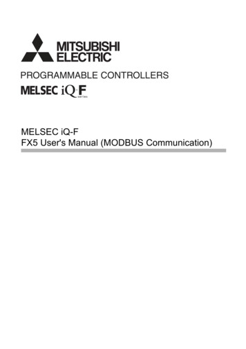
MPR50-IEM User ManualRev. 02BRIEF DESCRIPTIONMPR50 is a compact true diversity receiver designed for professional in-ear monitoringapplications. This receiver features a real TRUE DIVERSITY configuration along with a uniquewideband tuning range up to 232 MHz. Audio processing can be Stereo MPX with mix-modefunction or mono FM IFB mode.The output audio stage is especially design to have maximum audio peak-dynamic of 200 mW.MPR50-IEM is designed to be: “easy & quick to use” thanks tooautomatic setup functions (i.e. frequencies, scan for best channels),oremote configuration utilities (thru infrared or micro-USB interface) usingWisycom Manager applicationo OLED display with intuitive context menu navigation“extremely flexible”, with an incredible frequency agility up to 232MHzoMPR50-IEM-N: 470/700 MHz (TV ch 21/49)oMPR50-IEM-M:566/798 MHz (TV ch 33/61) “best in class performances”, thanks to the latest Wisycom technology the unit hasextreme RF sensitivity and immunity and superb audio quality “a light, robust and ergonomic design”Above a schematic with an overview of main receiver functions.1
MPR50-IEM User ManualRev. 02SAFETY INSTRUCTION Read this safety instruction and the manual firstFollow all instructions and information.Do not lose this manual.Do not use this apparatus under the rain or near the water.Do not install the apparatus near heaters or in hot environments, do not use outside theoperating temperature range.Do not open the apparatus, only qualified service technician are enabled to operate on it.The apparatus needs servicing when it is not properly working or is damaged by liquids,moisture or other objects are fallen in the apparatus.Use only accessories or replacement parts authorized or specified by the manufacturer.Clean the apparatus only with dry cloths, do not use liquids.Report the serial number and the purchasing date in front of the manual. It is needed tohave proper replacement parts or accessories from the manufacturer.When replacement parts are needed, use only replacement parts authorized from themanufacturer. Substitution with not authorized parts could result in electric shock,hazards or fire.Keep attention on all the labels with warnings or hazards on the apparatus.The apparatus is intended for professional use; anyway the manufacturer alerts theuser that the headphone output power of the apparatus could exceed the level of 85 dB(A) ofsound pressure level and this could be dangerous for the hearings. Do not use the headphonewith high power level or for long time. Reduce the power or suspend the hearing in case of anykind of hearing problem.2
MPR50-IEM User ManualRev. 02BATTERIESMPR50-IEM works with standard camera battery:2xIEC-LR6 1.5 size-AA alkaline or NiMh rechargeableKLIC 8000 (lithium-ion, rechargeable)Ricoh DB-50 (lithium-ion, rechargeable)DR9708 Duracell (lithium-ion, rechargeable)Battery status can be checked on OLED display or looking the status of LED indicator ON.Lithium-ion battery can be charged throughA. dedicated chargerB.integrated micro-usb-B connectorFor B item, the charging status can be checked looking the status of LED indicator ON.The receiver can be used also during the batteries charging with lithiumrechargeable batteries inside.Don’t use the receiver without batteries . The receiver powered thru micro-USB withoutbatteries doesn't work correctly.DO NOT operate the device with some new and some old batteries. Always replaceALL BATTERIES.Remember to remove the batteries when the device is not in use.3
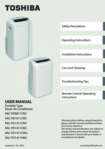
MPR50-IEM User ManualRev. 02PRODUCT OVERVIEWUpper PanelON LED indicatorHeadphone OutputOn/Off/VolumecontrolSMA connector Antenna BSMA connector Antenna ASMA antenna Connector A and BMPR50-IEM is supplied with two couple of antennas. According to the working band, differentantenna models can be supply. All the models haveAntenna Code labelblack cap and a black label with code in white colour.For more details see the section Accessories and PartsHeadphone OutputThe audio headphone output with 3.5 mm stereo jack socket lockable (TRS).Audio level can be adjusted with the Volume control knob and the Audio settings Pwr. Limitmenu.Maximum output power: 2x100mW @ 32ΩPin Assignment: Tip left (hot), Ring right (hot), Sleeve GndOn/Off/Volume controlThe control knob in the upper panel allows: To switch the receiver ON: turn the control knob volume control clockwise until it clicksTo switch the receiver OFF: turn the control knob volume control counter clockwise until itclicksTo adjust the volume: turn the control knob volume control until the volume set has thedesired level.To disable the lock volume: turn off and turn on the receiver within 1 second.NOTE: turn off and turn on the receiver within 1 second MPR50 restarts without the initialization phase after 1 second MPR50 restarts with complete initialization4
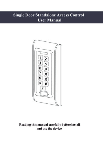
MPR50-IEM User ManualRev. 02Front panelMPR50-IEM allows an easy and quick configuration using buttons, RGB LED’s and an OLEDdisplay.ON Led IndicatorSCAN/DOWNButtonMENU/SELECTButtonRF Led IndicatorSYNC/UPMENU/EXITButtonInfrared Interface(IR)OLED DisplayThe receiver has a high contrast display. Pushing one of the 4 buttons while the receiver isactive (but the display is off), turn on automatically the display. After a time-out user setting(see Display Off timeout menu) the display turns off automatically.SEL & EXIT ButtonsPush the 2 buttons together to enter on the function menuSEL ButtonPush this button to navigate function menu’s and keep pushing to save the chosen setupEXIT ButtonPush this button to turn off the display.During menu navigation push this button to exit from current menu (escape function).SYNC/UP ButtonPush and keep this button to start a synchronisation with a Wisycom transmitter (followinstructions on display). Before starting synchronization IRDA must be enabled on Wisycomtransmitter.During menu navigation push this button to move -up and select the previous item.SCAN/DOWN ButtonPush and keep this button to start the automatic scan.During menu navigation push this button to move-down and select the previous item5
MPR50-IEM User ManualRev. 02charging statusbattery statusTuning phasepower upON & RF Led Indicators (Firmware rel. dgreenblueafter the tuning phase, a stereosignal is receivedfixedgreengreenafter the tuning phase, a monosignal is fthe batteries charge of thereceiver is good ( 25% lifetime)the batteries charge of thereceiver is low ( 25% lifetime)on/offon/offWHENwhen the receiver is power on,during the power up phasewhen the receiver is power on,after the power up phasewhen the receiver is power on,during a frequency changephase (see Gr-Ch or Frequencymenu)after the tuning phase, notransmitter is receivedoffoffthe batteries charge of thereceiver is very low ( 12%lifetime)battery errorduring batteries chargingoffduring batteries chargingoffduring batteries charginggreen/bluedevice in bootloader mode*MEANINGthe receiver is not ready to use,wait the status display on displaythe PLL is not locked on the selectfrequency, wait for lock ( about1second or less)the PLL is not locked on the selectfrequency, wait for lockthe receiver is locked on theselect frequency, the batteriescharge is good, no transmitter issynchronized with the receiver,no output audio availablethe transmitter is correctly tuned,the bars in the status displayshow the RF levels received fromantenna A and Bthe transmitter is correctly tuned,the bars in the status displayshow the RF levels received fromantenna A and B, in the statusdisplay M symbol appears upperthe battery levelthe batteries charge of thereceiver is goodchange or put on charge thebatteries as soon as possiblechange or put on charge thebatteries immediatelychange the batteriesthe batteries are charging ( 90%of complete charge)the batteries are charging ( 90%of charge reached)charge complete* to put the MPR50-IEM in boot mode: power on the device push and keep both UP and DOWN buttonsfor few seconds (until the led indicators light up, then release the buttons)6
MPR50-IEM User ManualRev. 02PUTTING THE DIVERSITY RECEIVER INTO OPERATION Insert the batteriesConnect the headphonesConnect the 2 antennas on the SMA connectorsTurn the knob control clockwise until it clicks and verify on the display the Antennamodel to use (if the connected antennas on the receiver is different from theantenna model indicate on the display, power off the receiver and replace them withthe proper model of antennas)after the power up phase, the Status display is showed on the OLED displayverify the setting and eventually adjust the settings using the Operating Menu Status display- Receiver Name (ex. MPR50-IEM RX)- Group (ex. Gr:00) and Channel (ex. Ch:01)- Frequency (ex. Fr:697.000 MHz)- Squelch (ex. Sq:12dBuV)- Mode (ex. Stereo)CSquelch levelA.A B CRF Level Antenna A and B (range 5 70 dBµV)Between the two RF bars there is a dotted line where the first 3 dots indicate6/8/10dBµV and the other 15 dots indicate the rest of the range (from 14 to 70dBµVwith step of 4dBµVAn orizzontal sign in a central row shows the setted Squelch levelB.deviation level (range of 54 dB, bar with 3dB steps; upper level 0dB, under level -54dB)the upper symbol:indicates presence of audio outputSTindicates absence of audio output (RF level Squelch)indicate absence of audio output (no pilot tone detected)NOTE: in case of absence of pilot tone and RF level Squelch, the symboldisplayC.batteries level for MPR50-IEM receiver the upper symbol:M indicates receiving of a mono signalS7indicates receiving of a stereo signalwill be
MPR50-IEM User ManualMENUHead jackOut modeRev. 02Mono/StereoMono/Stereo/MixBalance/Mix modeAudioSettingsEqualizerVol. boostOutput loadPWR LimitGr-ChFrequencyEdit RXSquelchScanNameMENUQuick MenuSettingsDisplayInfraredSyncLEDLock volumeFixed/Max LevelPilot SquelchAdvancedCloneInfoPreset8OP w (-12 12)Hi (-12 12)0/5/10/15dB32Ω/16ΩOFF/100mW/50mWGR (0 39)CH (0 59)N: 470.000 700.000M: 566.000 798.000OFF-0/3/6/9/12/15/18/21/24//28/32/36/40/46 dBµVChannelGR 00 - 39Groupsmoregroups (max 10)Scan nowfreq.Min/freq. Max/Squelch scanFreqstep (100 or 200 kHz)Scan BTNChannel/Groups/FreqView lastDeploy12 charactersex. RECEIVER-123Bal /Mix; Clone; Ch; Vol view; OFFContrast0 5Low timeout (sec)5 60 steps 5Off timeout (sec)10 120 steps 10 - /3/4/5Act TopOff /Led ON /Led RF /Led OnlyDisable/Max/Fixed-64 to 0 dBYes/NoAdd00 23Loaddefault/0/.Delete00 23Delete allIEM/IFBMPR50-I470 700xxxxxxxVersionOption2.36 Volt01/2/3/4/5/6/Factory1/2/3/4/5/61NPreset parametersClone parameters
MPR50-IEM User ManualRev. 02From Status Display push SEL and EXIT together to enter on theMain menuUse UP/DOWN to navigate on all available menusPush SEL to select a menu itemUse UP/DOWN to move on the different parameters of the menuPush SEL to modify the parameter menuUse UP/DOWN to change the parameter valueKeep push SEL to save changingPush EXIT to return on the Main MenuPush EXIT to return on the Status displayAudio settingsThe Audio settings menu allows to configure the audio output.PARAMETERSETTINGMEANINGSelect Mono or Stereo according to the jack headphoneMono/StereoHead jackconnector used.The left and right signals are available as usual. The BalanceStereosetting serves to adjust the balance between the left andright stereo signal.The left-right signals are mixed and are available as a monoMonosignal in both headphone channels.Out modeThe left-right signals are mixed and are available as a monosignal in both headphone channels.MixThe Mix mode setting serves to adjust the relative levels ofthe two separate channels in the mixer mono signal.Use the Up and Down arrows to change the balancebetween Left and Right channel (available only with OutMode sets on Stereo)BalanceUse the Up and Down arrows to change the mix betweenChannel1 and Channel2 (available only with Out Mode setson Mix)Mix modeEqualizer9Low and Highfrequencies-12dB/ 12dB1dB stepsThis menu allows to of adjusting the gain of low and highfrequency components (bass and treble) within the audiosignal.1. Push UP/DOWN button to increase/decrease thegain of the Low frequencies (50Hz)2. Push SEL button to shift on High frequencies,3. Push UP/DOWN button to increase/decrease thegain of the High frequencies (10kHz)4. Keep push SEL button to SAVE
MPR50-IEM User ManualVol. boost0/5/10/15dBOutput load16Ω/32ΩPwr limitOFF (only using lithiumbattery) / 100mW /50mWRev. 02This menu allows to increase or decrease the volume of theoutput headphones, selectable from 0dB to 15 dB. Set theappropriate volume boost and then adjust the volume withthe control knob.Set the Output load according to the impendence of theheadphones connectedThis menu allows to limit the power output. If set toOFF(only lithium battery), there is no power limit control. Ifset to OFF using alkaline or NiMH batteries, the receiver setautomatically the max value permitted (100mW)NOTE: When the volume knob is rotated, appears a screen with avolume bar and the values of Pwr limit, Outpul load and Vol. boostEdit RXThe Edit RX menu allows to configure the radio frequency settings.PARAMETERGr-ChFrequencySquelchSETTING0 39 groups0 59 channels470 700 MHzfor MPR50-IEM-N566 798 MHzfor MPR50-IEM-MOFF Select current group and channel. Group name andchannel frequency are displayed on the right.If the specific group/channel is not locked, the frequencycan be edited in this menu.This menu allows to disable the RF squelch or to setup thedesired squelch level in dBuV (note 0 dBuV is equal to 107 dBm).It allows making three types of scan over a desiredchannel, group or frequency. MPR50-IEM manages up to2400 custom frequencies organized in 40 groups of 60channels each. This extreme flexibility makes the scanfunction very flexible.This function can be called also using the dedicatedDOWN&SEL buttons pushed together.Scan“Squelch scan” indicates the threshold below which achannel is considered as free or almost free.“Scan BTN” is the parameter to set the rapid functioncalled pressing DOWN&SEL buttons together.It’s possible to set Channel, Group or Frequency scan.10
MPR50-IEM User ManualRev. 02“View last” allows to see the result of the last scanoperation.“Deploy” allows to send to a MTK952 the last scan.From the transmitter it’s possible to see the graphic of thelast scan and choose the frequency to tune.(*)As per Wisycom standard, group 00 and group 01 or 09 are special; respectively the “centerfrequency” (474,482/ MHz) and the intergap frequency (i.e. 470/478/486/ MHz). A scan on group00 will reveal in few seconds the overall DVB-T occupation on the area, while a scan on group 01 willgive possible working frequency, usable also in presence of strong DVB-T signal (sort to speak workingin the band-guard of 2 digital television channels).“Scan now” menuThe following table lists the three types of scans that can be performedOnce started a Channel scan operation the receiver asks forgroup to be used*. Press and hold the SEL button to select thegroup to scan.Then it prompts to turn off all transmitters.So press SEL to start the scan!ChannelAfter few seconds, scan results are displayed sorted by level,making easier to pick up the best one.The dotted line in the graph indicate the squelch threshold.Under the graph are reported the following parameters:Ch: ChannelRank: Ranking positionFreq: FrequencyLev: RF levelPushing simultaneously UP and DOWN button, the results canbe also displayed on a chart in ascending order according tothe number of the channel.11
MPR50-IEM User ManualRev. 02After the selection of the desired channel, a screen appearswith the selected frequency, channel and group and it ispossible to Set or Synchronize the receiver with thetransmitter. We recommend setting the frequency and thensynchronize it with the transmitter.If the scan is done on Groups, you can choose a maximum of10 groups from among the 40 groups shown in the table(Press the SEL button to select and press it again to deselect).In the upper left shows the number of the selected group andthe number of selected groups, while in the upper right cornerthere is the item "START" to start the scan.To select START, go to the box 39 and press the "UP" button orgo to the box 0 and press the "DOWN" button, so press SEL torun the scansion.Then it prompts to turn off all transmitters.So press SEL to start the scan!GroupsAfter few seconds, scan results are displayed on a histogram.Each column of the histogram is divided into two parts by ablack line. The lower part indicates the number of freechannels (RF level Squelch level - 6dBµV) in the group, whilethe upper one the number of channels almost free(Squelch level RF level Squelch level - 6dBµV).We recommend to choose the group with the highest numberof free channels.Press SEL to select the desiderate group and choose thechannel as in “Channel scan”After the selection of the desired channel, a screen appearswith the selected frequency, channel and group and it ispossible to Set or Synchronize the receiver with thetransmitter. We recommend setting the frequency and thensynchronize it with the transmitter.12
MPR50-IEM User ManualRev. 02The Frequency scan allows to select a range of frequency toscan, between a maximum and a minimum value and the stepwith which to perform the scans. Press and hold the SELbutton to confirm.Then it prompts to turn off all transmitters.So press SEL to start the scan!FreqAfter few seconds, scan results are displayed on a chart inascending order according to the frequency (step 1MHz). Thedotted line in the graph indicate the squelch threshold.Pushing simultaneously UP and DOWN button it’s possible tozoom the graph to show all the steps of scanAfter the selection of the desired frequency, a screen appearswith the selected frequency and the RF level and it is possibleto Set or Synchronize the receiver with the transmitter. Werecommend setting the frequency and then synchronize itwith the transmitter.13
MPR50-IEM User ManualRev. 02SettingsThe Settings menu allows to configure main settings of the device.PARAMETER SETTINGMEANINGThe name menu allows to change the name of thereceiver. This is the name displayed in the top ofthe Status display and it is the name sent to the12 case-sensitive alphanumeric transmitter with the sync function (for theNamecharacterstransmitter with this advanced capability).Use the UP/DOWN buttons to change the selectedcharacter and push SEL button to switch to thenext character.The quick menu is displayed pushing UP or DOWNbuttons when the receiver is on the Status display.Set to Bal/Mix to enter quickly to the Balance/Mixmode menu (according to the Out modeconfigured).Set to Clone to enter into “Advanced Clone Load”Bal/Mix ; Clone ; Ch; Volumemenu.QuickMenuview; OffSet to Channel to enter into “Edit RX Gr-Ch”menu.Set to Volume view to view quickly the VolumescreenSet to Off for disable this function (if is set “Off”and UP or DOWN buttons are pushed, nothinghappens).Contrast0 5Change contrast display from 0 (min) to 5 (max).Low timeout sets the timeout from 5 to 60 secondsLow timeout 5 60 (steps 5)(5sec steps) to decrease the brightness display.DisplayOff timeout sets the timeout from 10 to 12010 120 (steps 10)Off timeoutseconds in 10 sec. steps to turn off the display.or OFFWith OFF setting the display never turns off.Directionup/downTo change direction of display3 LED setting are available:FullFull: LED indicators works normally;AlarmModeAlarm: LED indicators lights up only when an alarmOFFhappened;OFF: LED indicators remain off.LEDBrightness1/2/3/4/5OFFTo change the behavior of the LED on the top (nearLED ONthe headphone connector)Act TopLED RFLED ONLY14
MPR50-IEM User ManualRev. 02InfraredBy this menu, MPR50-IEM can be connected to IRDA for setup or firmware upgrades.When the Infrared interface is active, the following screen is displayed.NOTE: while in this menu display is not automatically turned off.SyncThe SYNC function is useful to tune a transmitter on the samefrequency of the receiver via the IR interface. Before starting thesync function tune the receiver on desired channel, manually orusing the SCAN utility. After this, enable the IR interface on thetransmitter. Now press UP&EXIT buttons together or enter in theSync menu to start the SYNC function. Keep the IR window of the transmitter in front of the IRwindow of the receiver and, as soon as the connection is done, the receiver will send to thetransmitter all the information needed.If the operation is not possible, (i.e. the frequency range of the transmitter is not compatible withthe frequency of the receiver), the display will show an error message.If the transmitter has the function “NAME” enabled, when the sync function is completed it willshow the same name of the synchronized receiver.AdvancedThe Advanced menu allows to manage advanced settings.PARAMETERSETTINGMEANINGThanks to this menu it is possible to lock thevolume potentiometer to a fixed value or limit theDisable / Max / Fixedvolume to a maximum value.Lock volumeSet to disable if you don’t want to lock or limit thevolumeUse this menu to set- the Max level is Lock Volume is set to MaxFixed/Max Level -64 to 0dB- the Fixed level is Lock Volume is set to FixedWhen the Pilot tone is enabled, the audio output ismuted unless the correct carrier is detected(19kHz).Yes / NoWhen the Pilot tone is disable, the audio output isPilot Squelchmuted if RF level Squelch level.For the presence/absence of audio output, checkthe upper symbol in the status display.15
MPR50-IEM User ManualAddLoadDeleteClone *00 23Default/00 2300 23Delete allRev. 02To add a cloneTo load a clone *To delete a clone *To delete all the clones ** It appears if exist at least a1 cloneThis menu allows to change the type of operationbetween:- IEM: that is a stereo transmission, MPX decodingwith 19 kHz sync carrierIEM/IFBOP mode- IFB: that is a mono transmission with 100 kHzbandwidth (narrowband)NOTE: remember to set the pilot squelch to Nowhen set to IFB!* A clone is a partial configuration of the MPR50-IEM which can be copied from a receiver to anotherusing the IRDA interface. It consists of the same parameters of pre-set configuration for less thandisplay, quick menu and headphones parameters (see the Operating menu for more details).From firmware version v1.3 the MPR50-IEM is able to manage up to 24 clones (from 00 to 23). Themenus of the clone management allow to add/load and delete a clone.How to add a cloneOut modeBalanceEqualizerVol boostPilot toneGr-ChSquelchRX NameClone nameEnable the IRDA interface on the RX fromwhich take the configuration (Infrared menu)Put the receivers faceto faceAt the end of the process the nameof the clone will be identify with thename of the receiver.16Enter in the Add menu and select thewanted clone number. Then push SELto start the IRDA communication.
MPR50-IEM User ManualRev. 02How to load a cloneUse Clone Load menu or UP/DOWN button (if the quick menu is configured to clone) to load aclone. Afterwards push the arrows to change clone, SEL to activeted the clone and EXIT to exitwithout changing.Ex.The configuration saved before the loading of the clone is saved onthe clone named “default”, therefore loading the default “clone”allows to return with the previous settings. The followingarrows displayed near the clone number indicates the currentlyclone loaded.Loading a clone, all the clone parameters are set on the receiver. The follow icon appears on theright of the display indicating that a clone is loaded. The number and the name of the clone aredisplayed on the top of the display menu and a brief list of the main parameters are displayed on thestatus menu.Name of the cloneNumber of the clonesymbol to indicate that aclone is loadedis loadedMain parametersNOTE: the clones are saved on the EPROM and remains saved also after a reboot of the device.NOTE: If a clone is loaded and then a reboot is executed, the MPR50-IEM always restarts with theprevious configuration (default clone).NOTE: When a clone is loaded, it's not possible change the parametersNOTE: When a clone with Power limit set to OFF is loaded on the receiver but the receiver isn’tusing Lithium battery, the power limit is set automatically to the max value permitted for no lithiumbattery (that is 100mW).17
MPR50-IEM User ManualRev. 02Infothe INFO function shows many important features or information of MPR50-IEM sMEANINGWisycom receiver modelFrequencies range of workingSerial numberVersion * Firmware versionBLBootloader versionAppApplication versionVersionHardware versionMPR50-IEM OptionsOptionN freq. range 470 700 MHz,M freq. range 566 798 MHzBatteries voltageNumber of errors.If the number of errors is 0 push SEL button to enter on theErrors list. For each error a brief description and the error code isshowed. For more information, please see the Error List .63d6N3.71 Volt4* The Firmware Version recaps BL (Bootloader Version) and App (Application version).PresetThis menu allows to load/save 6 user presets or load the Factory actorySave1/2/3/4/5/618MEANINGSelect the Restore submenu and chose the presetsto load: user presets or Factory preset. Push andkeep SEL button to load the preset.Select the Save submenu and chose the user presetsto save. Push and keep SEL button to save thepreset
MPR50-IEM User ManualRev. 02ERROR LISTWhen an error occurs, the receiverA. shows a message on the displayand for some error typesB. increases the errors counter in the info menuC. inserts the error type and code on the error list in the info menuWhen the error is solved, the message on the display disappear, but the error information(code and description) are available on the error list in the Info menu (only for some error, seethe below table).NOTE1: When the receiver is reset the error information (code and error type on the list) arelost, with the exception of errors codes 87/88/89/8A.NOTE2: To reset the error counter and the errors list, it is necessary to contact Wisycom.HW init failedMessage on display(A)HW init failedBattery LowBattery LowBattery charge failedBattery charge failedI2C communication errorDevice ID copy1 invalidMemory recoveredDevice ID copy2 invalidMemory recoveredRF copy1 invalidMemory recoveredRF copy2 invalidMemory recoveredPLL unlockedI2C communication errorDevice ID copy1 invalidMemory recoveredDevice ID copy2 invalidMemory recoveredRF copy1 invalidMemory recoveredRF copy2 invalidMemory recovered-I2C access failed04Device ID copy 187Device ID copy 288RF mem copy 189RF mem copy 28APLL unlocked84CH mem header-CH mem header85Param mem header-Param mem header86Errors19Error type(C)Code(C)
MPR50-IEM User ManualRev. 02TROUBLESHOOTINGProblemPossible cause“HW init failed” messageappears on the display“Battery Low” messageappears on the display“Battery charge failed”message appears on thedisplay“I2C communication error”message appears on thedisplay“Device ID copy1 invalidMemory recovered”message appears on thedisplay“Device ID copy2 invalidMemory recovered”message appears on thedisplay“RF copy1 invalidMemory recovered”message appears on thedisplay“RF copy2 invalidMemory recovered”message appears on thedisplayThe Serial Number of thereceiver in the Info menuis UNCALThe errors 87 (Device IDcopy 1 ) and 88 (Device IDcopy 2) appear in theerrors listThe errors 89 (RF mem.copy 1 ) and 8A (RF meme.copy 2) appear in theerrors listThe receiver is not able totuned on the selectedfrequency and the ON ledindicator remains red20Error during the hardware initializationphaseLow level on the batteryPossible solution-reset the receiver, if theproblem persists send to repairat Wisycom Repair Centre- change batteries or- recharge the batteriesError during batteries charger(damage batteries or wrong batteries)- change batteriesCommunication error on bus I2C- send to repair at WisycomRepair CentreError during the initialization phase. TheCRC-16 check of device data (copy 1)detects error.- nothing (the receiverautomatically replace thecorrupt copy1 with copy2)Error during the initialization phase. TheCRC-16 check of device data (copy 2)detects error.- nothing (the receiverautomatically replace thecorrupt copy2 with copy1)Error during the initialization phase. TheCRC-16 check of RF data (copy 1) detectserror.- nothing (the receiverautomatically replace thecorrupt copy1 with copy2)Error during the initialization phase. TheCRC-16 check of RF data (copy 2) detectserror.- nothing (the receiverautomatically replace thecorrupt copy2 with copy1)Error during the initialization phase. TheCRC-16 check of device data (copy 1 andcopy 2) detects error.- send to repair at WisycomRepair CentreError during the initialization phase. TheCRC-16 check of device data (copy 1 andcopy 2) detects error.- If the Serial Number in theInfo menu is UNCAL, then sendto repair at Wisycom RepairCentre- If the Serial Number in theInfo menu is not UNCAL,continue to use the receiverError during the initialization phase. TheCRC-16 check of RF data (copy 1 and copy2) detects error.- contact Wisycom for moreinformationError during frequency tuning- try to change the frequency, ifthe problem persists send torepair at Wisycom RepairCentre
MPR50-IEM User ManualThe frequencies of all thechannels and groups isequal to the lowerfrequency of the receiverError in the channel memory during theinitialization phase.(according to the receiver470 MHz for MPR50-IEM-N566
- Frequency (ex. Fr:697.000 MHz) - Squelch (ex. Sq:12dBuV) - Mode (ex. Stereo) A. RF Level Antenna A and B (range 5 70 dBµV) Between the two RF bars there is a dotted line where the first 3 dots indicate 6/8/10dBµV and the other 15 dots indicate th