Transcription
DEPARTMENT OF ELECTRICAL ENGINEERINGBASIC ELECTRICAL ENGINEERING (4 credit)Course Code: BEE1101(1ST AND 2ND SEMESTER)SYALLABUSMODULE-I (10 HOURS)DC Networks: Kirchhoff's laws, node and mesh analysis, Delta-star and star-deltatransformations. Superposition, Thevenin’s and Norton's theorem. Transients in RL, R-C and R-L-C circuits with DC Excitation.Single Phase AC Circuits: Single phase EMF generation, average and effectivevalues of sinusoids, j operations, complex representation of impedances, phasordiagrams, power factor, power in complex notation, solution of series and parallelcircuits. Introduction to resonance in series RLC circuit.Three Phase AC Circuit: Three phase EMF generation, delta and star connection,Line and Phase quantities. Solutions of 3-phase circuits with balanced load. Powerin 3-phase balanced circuits.MODULE-II (10 HOURS)Magnetic Circuits: B-H Curve, Hysteresis, Permeability and reluctance, solution ofsimple magnetic circuits, Hysteresis and Eddy current losses.DC Generator: Different types, Principle of Operation of DC generator, EMFequation, methods of excitation. DC Motor: Back e.m.f., speed and torque of a DCMotor, Conditions for maximum Power. Speed control of DC shunt motor.Transformers: Construction and Principle of operation of single-phase transformer,EMF equation, Single-phase autotransformer.MODULE-III (10 HOURS)Three phase Induction Motor: Construction and principle of operation, types; Sliptorque characteristics.
Synchronous Machines: Construction & principle of operation of Synchronousgenerator and motor. EMF equation, Voltage regulation, Applications and startingof Synchronous motor.Introduction to single-phase induction Motor.MODULE-IV (10 HOURS)Measuring Instruments: DC PMMC instruments, Extension of range by shunts andmultipliers. Moving iron ammeters and voltmeters, Dynamometer type Wattmeters, Induction type Energy Meter.Power supply systems: Principle of generation - thermal, hydel and nuclear.Transmission and distribution of electric energy. Introduction to Electric Heating& Welding.TEXT BOOK[1].Edward Hughes (revised by Ian McKenzie Smith). "Electrical & ElectronicsTechnology" Pearson Education Limited. Indian Reprint 2002.REFERENCE BOOKS[2].H.Cotton, “Advanced Electrical Technology", CBS Publishers, New Delhi,7th Edition.[3].C.L. Wadhwa, “Electrical Engineering”, New Age International Publishers.[4].D.Kulshreshtha, “ Basic Electrical Engineering” TMH[5].S. Parker Smith: “Problems in Electrical Engineering" Asia Publications.
MODULE-ID.C NETWORKS1.1 Kirchoff’s Laws:1.1.1. Kirchoff’s current law or point law (KCL)Statement:- In any electrical network, the algebraic sum of the currentsmeeting at a point is zero.Σ I 0 at a junction or nodeAssumption:- Incoming current positiveOutgoing current negative1.1.2. Kirchoff’s voltage law or mesh law (KVL)Statement:- The algebraic sum of the products of currents and resistances ineach of the conductors in any closed path (or mesh) in a network plus thealgebraic sum of the emfs in that path is zero.Σ IR Σemf 0 .round the meshAssumption:- i) Rise in voltage (If we go from negative terminal of thebattery to positive terminal) positiveii) Fall in voltage (If we go from positive terminal of the battery to negativeterminal) negativeiii) If we go through the resistor in the same direction as current then there isa fall in potential. Hence this voltage is taken as negative.iv)If we go through the resistor against the direction of current then there is arise in potential. Hence this voltage drop is taken as positive.
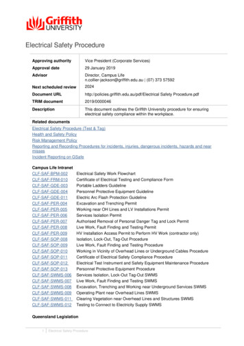
Example:- Write the loop equation for the given circuit below(Supplementary exam 2004)r1E1ir2E2E3r3Solution: Apply KVL to the loop, ir1 E 1 ir2 E 2 ir3 E 3 0 E 1 E 2 E 3 ir1 ir2 ir3 E 1 E 2 E 3 i ( r1 r2 r3 )1.2.MAXWELL’S LOOP CURRENT METHOD (MESH ANALYSIS)Statement:- This method determines branch currents and voltages across theelements of a network. The following process is followed in this method: Here, instead of taking branch currents (as in Kirchoff’s law) loop currentsare taken which are assumed to flow in the clockwise direction. Branch currents can be found in terms of loop currents Sign conventions for the IR drops and battery emfs are the same as forKirchoff’s law. This method is easier if all the sources are given as voltage sources. If thereis a current source present in a network then convert it into equivalentvoltage source.
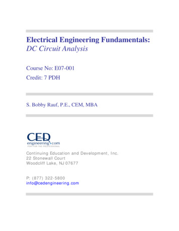
Explanation:Consider a network as shown in Fig. below. It contains two meshes. Let I1 andI2 are the mesh currents of two meshes directed in clockwise.Apply KVL to mesh-1,V1 -I1 R 1 - ( I1 -I 2 ) R 3 0Apply KVL to mesh-2,-I 2 R 2 -V2 - ( I 2 -I1 ) R 3 0When we consider mesh-1, the current I1 is greater than I2. So, current throughR3 is I1-I2. Similarly, when we consider mesh-2, the current I2 is greater than I1.So, current through R3 is I2 – I1.Example: Find I1, I2 and I3 in the network shown in Fig below using loopcurrent method40 V10ΩAB20Ω10ΩEG10 V50 V20Ω10 VI1I2I310ΩDSolution:- For mesh ABCDA,CFH
-I 1 1 0 - ( I 1 -I 2 ) 2 0 -1 0 0 3 I 1 -2 I 2 -1(1 )For mesh BEFCB,4 0 -I 2 2 0 1 0 - ( I 2 -I 3 ) 1 0 - ( I 2 -I 1 ) 2 0 0 2 I 1 -5 I 2 I 3 -5(2 )For mesh EGHFE,-1 0 I 3 5 0 ( I 3 I 2 ) 1 0 1 0 0 I 2 -2 I 3 -4(3 )Equation (2) x 2 Equation (3)4 I1 -9 I 2 -1 4(4 )Solving eqn (1) & eqn (4)I1 1 A, I2 2 A, I3 3 A1.3.NODAL ANALYSISStatement:- This method determines branch currents in the circuit and alsovoltages at individual nodes.The following steps are adopted in this method:Identify all the nodes in the network.One of these nodes is taken as reference node in at zero potentialThe node voltages are measured w.r.t the reference nodeKCL to find current expression for each nodeThis method is easier if all the current sources are present. If any voltagesource is present, convert it to current source
The number of simultaneous equations to be solved becomes (n-1) where ‘n’is the number of independent nodes.Explanation:-At node ‘a’I1 I2 I3By ohms law,I1 Therefore,E1 VaE VV, I2 2 a , I3 aR1R2R3 111 E EVa 1 2 0 R1 R2 R3 R1 R2or, 111 E EVa 1 2 0 R1 R2 R3 R1 R2or, 1 1 1 E EVa 1 2 0 R1 R2 R3 R1 R2Hence,Node voltage multiplied by sum of all the conductance connected to thisnode. This term is positiveThe node voltage at the other end of each branch (connected to this nodemultiplied by conductance of this branch). This term is negative.
Example:- Use nodal analysis to find currents in the different branches of thecircuit shown below.(Supplementary Exam July- 2004)Solution:Let V1 and V2 are the voltages of two nodes as shown in Fig belowApplying KCL to node-1, we get12 V1 0 V1 V 2 V1 0213 36 3V1 6V1 2V 2 2V1 0 11V1 2V 2 36.(1)Again applying KCL to node-2, we get:-
0 V26 V2V1 V 2 0354 2 0V1 4 7 V 2 9 0 0 2 0 V 1 4 7 V 2 9 0 .( 2 )Solving Eq (1) and (2) we get V1 3.924 Volt and V2 3.584 volt12-V1 12-3.924 4.038 ACurrent through 2 Ω resistance 2 20-V1Current through 1 Ω resistance 1 -3.924 AV1 -V2 0.1133 ACurrent through 3 Ω resistance 30-V2Current through 5 Ω resistance 5 -0.7168 ACurrent through 4 Ω resistance 6-V2 0.604 A4As currents through 1Ω and 5Ω are negative, so actually their directions areopposite to the assumptions.1.4.STAR-DELTA CONVERSIONNeed:- Complicated networks can be simplified by successively replacing deltamesh to star equivalent system and vice-versa.In delta network, three resistors are connected in delta fashion ( ) and in starnetwork three resistors are connected in wye (Y) fashion.
Fig. 1.4.1.a)Delta connectionb) Star connection1.4.1. Delta to Star Conversion:- From Fig. 1.4.1 (a), : Between A & B,there are two parallel path.Resistance between terminal A & B RAB ( RBC RCA )RAB RBC RCAFrom Fig. 1.4.1 (b), STAR: Between A & B two series resistances arethere RA RB. So, terminal resistances have to be the same.RA RB R AB ( R BC RCA) .(1)R AB R BC RCARB RC R BC ( RCA R AB ).( 2 )R AB R BC RCARC R A RCA ( R AB R BC ).( 3 )R AB R BC RCAEq {(1)-(2)} (3) & Solving,-RA R AB RCA.(4)R AB R BC RCARB R AB R BC.(5)R AB R BC RCA
RC RCA R BC.( 6 )R AB R BC RCAEasy way to remember:-Any arm of star connection Pr oduct of two adjacent arms of deltasum of arms of delta1.4.2. Star to Delta conversionEq {(1) X (2)} (2) X (3) (3) X (1) & Simplifying,R AB R A R B R B RC RC R AR R RA RB A BRCRCR RRB CC A RBC R RCA RRBRRACRRBCAEasy way to remember:- Resistance between two terminals of delta sum of starresistance connected to those terminals product of the same to resistancedivided by the third resistance.
Example(delta to star):- Convert the following Delta Resistive Network into an equivalentStar Network.NETWORK THEOREMS SUPERPOSITION THEOREMTHEVENIN’S THEOREMNORTON’S THEOREMMAXIMUM POWER TRANSFER THEOREM1. Superposition theoremStatement:- In a network of linear resistances containing more than onegenerator (or source of emf), the current which flows at any point is the sumof all the currents which would flow at that point if each generator wereconsidered separately and all the other generators replaced for the time beingby resistances equal to their internal resistanceresistance.
Example:- By means of superposition theorem, calculate the currents in thenetwork shown.Step 1. Considering 10 V batteryReqI1bI 2bI3b2 18 1 2 .8 Ω2 1810 3 .5 7 A2 .818 3 .5 7 3 .2 1 A20 I1b I 2b 0 .3 6 A
Step 2. Considering 20 V batteryI1cI2cI3c1Ω18 Ω2Ω20 VReqI 2cI1cI3b1 18 2 2 .9 5 Ω1 1820 6 .7 8 A2 .9 518 6 .7 8 6 .4 2 A19 I 2c I1c 0 .3 6 A Step 3. ResultsI1 I1b I1c 3.57 6.42 2.85AI 2 I 2c I 2b 6.78 3.21 3.57AI3 I3b I3c 0.36 0.36 0.72A2. SOURCE CONVERSION:Statement: A voltage source (V) with a series resistance (R) can beconverted to a current source (I V/R) with a parallel resistance (R) and viceversa.
Proof:-IL IL IVRX RLRXRX RL(1)(2)From Eq. (1) & (2)V IR X(3) STATEMENT: The two circuits are said to be electrically equivalent if theysupply equal load currents with the same resistance connected across theirterminals. voltage source having a voltage V and source resistance Rx can be replacedby I( V/Rx) and a source resistance Rx in parallel with current source. Current source I and source resistance Rx can be replaced by a voltagesource V ( IRx) and a source resistance Rx in series with V.3. THEVENIN’S THEOREM:Statement:- Any pair of terminals AB of a linear active network may bereplaced by an equivalent voltage source in series with an equivalent
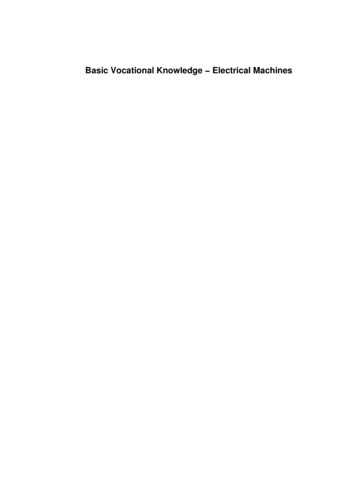
resistance Rth. The value of Vth (called the Thevenin’s voltage) is equal topotential difference between the terminals AB when they are open circuited,and Rth is the equivalent resistance looking into the network at AB with theindependent active sources set to zero i.e with all the independent voltagesources short-circuited and all the independent current sources opencircuited.Example:- Find VX by first finding VTH and RTH to the left of A-B4Ω12 Ω30 V 6Ω A 2ΩVX BSolution:- step1. First remove everything to the right of A-B.4Ω12 Ω30 V 6Ω V AB AB( 3 0 )( 6 ) 10V6 12Notice that there is no current flowing in the 4 Ω resistor (A-B) is open. Thusthere can be no voltage across the resistor.Step 2. To find RthWe now deactivate the sources to the left of A-B and find the resistance seenlooking in these terminals.
4Ω12 Ω A6Ω BRTH 12 6 4 8 ΩStep 3. To find VxAfter having found the Thevenin circuit, we connect this to the load in order tofind VX.RTH8ΩVTH 10 VA 2ΩVXB VX ( 10 )( 2 ) 2V2 84. NORTON’S THEOREM:Statement: Any two terminal linear active network (containing independentvoltage and current sources), may be replaced by a constant current sourceIN in parallel with a resistance RN, where IN is the current flowing through ashort circuit placed across the terminals and RN is the equivalent resistanceof the network as seen from the two terminals with all sources replaced bytheir internal resistance.
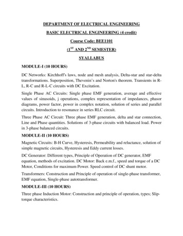
Example: Find the Norton equivalent circuit to the left of terminals A-B forthe network shown below. Connect the Norton equivalent circuit to the loadand find the current in the 50 Ω resistor.10 A40 Ω20 Ω A 60 Ω50 V50 ΩSolution: B10 A40 Ω20 Ω 50 V60 ΩISSFig. Circuit to find INORTONI SS 10.7 AIt can also be shown that by deactivating the sources,We find the resistancelooking into terminals A-B is RN 55 ΩRN and RTH will always be the same value for a given circuit. The Nortonequivalent circuit tied to the load is shown below.10.7 A55 Ω50 Ω
5. MAXIMUM POWER TRANSFER THEOREM: Statement: For any power source, the maximum power transferred from thepower source to the load is when the resistance of the load RL is equal to theequivalent or input resistance of the power source (Rin RTh or RN). The process used to make RL Rin is called impedance matching.Explanation:I VTHR TH R LVTH 2 R LPL I R L (R TH R L ) 22For PL to be maximum,dPL 0dR LOr, R L R TH2So, Maximum power drawn by R L I R L VTH 2Power supplied by the source ( R TH R L )VTH 2 R L( 2R L )2VTH 2 4R L
TRANSIENTSStatement: Sudden change in electrical circuit. Amplitude dies out and frequency is more Transient disturbances are produced whenever:An apparatus or circuit is suddenly connected to or disconnected from thesupply.A circuit is shortedThere is a sudden change in the applied voltage from one finite value toanother.Transients are produced whenever different circuits are suddenlyswitched on or off from the supply voltage.Resultant current consists of two parts:A final steady state or normal currentA transient current superimposed on the steady state current Transient currents are not driven by any part of the applied voltage butare entirely associated with changes in the stored energy in inductors andcapacitors. Since there is no stored energy in resistors, there are no transients in pureresistive circuit.Transient in R-L Series circuit:-When Switch ‘S’ is connected to ‘1’,
V R i Ldidti i s s i trVRi ss di 0dti tr R i LdiR i 0dtL Rdi idtL Rdi dtiL Rln i t ; i tr K eLiis st ri VRKVR RtLe- RLt KeAt t 0, i 0 So,V KR-VK RV i 1 eR 0 RtL RLt
LRis called time constant and is called damping coefficient of the circuitRL-t VR iR V 1-e λ diEmf of self inductance is -L i t Rdtλ If t λ, then it I0 e-1 I0e-1 I0/e I0/2.718 0.37 I0Hence, time period of a circuit is the time during which the transient currentdecrease to 0.37 of its initial value.Transient in R-C Series Circuit:Consider an ac circuit containing a resistor of resistance R ohms and a capacitor ofcapacitance C farad across an a.c source of rms voltage V volts as shown in Fig.below:-
Charging of RCV V R VCWhen switch is connected to ‘1’ (charging):V VR Vc1 id tCdiiR 0dtCdi1 i 0dtR CV iR i K eA t-tR Ct 0 -tτ;i I 0 eVVK ;So,i eRR tRC tVVVVVRcccc iR I 0 e 1C1 C I1Cid t 0 tR V eτ tt I0e t eτ V 1 e tτ τ0 t ( τ ) τ V e τ0 t 01 VC R( R C)
Discharging of RCWhen connected to ‘2’ in the Fig. above,1 id t 0CdiiR 0dtCRi i K eAt t 0; i VRi -I 0 e tRC(voltage across capacitor starts disch arg ing in opposite direction to the original current direction)-tR C -I 0 e-tτ
Transient in R-L-C Series Circuit Two types of energy:- Electromagnetic and electrostatic. So any suddenchange in the conditions of the circuit involves redistribution of these twoenergies. Transient current produced due to this redistribution may be unidirectionaland decaying oscillatory.From the above Fig,di1iR L id t VdtCdid 2iiR L 0dtCdt2d 2iR di1 i 02L dtLCdtα β α β b 2 -4 a c2a-b -R L Rα β 2L Rα 2L24 R LC L 2 R 2L and β 2 1LC R 2L 2 1LC
Solution of differential equation is:-i K 1e P1t K 2 e P2 tRoots are:α β P1 ;α-β P2K 1 &K 2 depends on boundary condition2 R 1i.e 〉 2L LCCase 1: High loss circuit:-OverdampedIn this case, β is positive real quantity. Hence P1 and P2 are real but unequal.P1 ti K 1ei K 1e ( Kα βi K 1eα t ei eαt2)tβ t K 1 eeP2 t K Kβ t22 Ke(α βeαte2e)t β t β t The expression of ‘i’ is over damped transient non-oscillatory current.2CASE 2:- Low-loss circuit:1 R 2L LCi.e UnderdampedIn this case, β is imaginary. Hence roots are complex conjugateP1 α j β ; P2 α j βi K 1 e P1 t K 2 e P2 ti K 1e (α j β )ti K 1eα t ejβ ti e α t K 1 e K 2e(α j β )t K 2 eα t e jβ t K 2e jβ tjβ t The expression of ‘i’ is damped oscillatory2CASE 3:1 R 2LLC i.e Critical dampingIn this case β 0, Hence roots P1 & P2 are real and equal.
P1 α 0 α ; P 2 α -0 αi K 1e αt K 2 te αtThe above expression is of critical damping because current is reduced to almostzero in the shortest possible time.Example: A coil having a resistance of 2Ω and an inductance of 1 H is switchedon to a 10 V D.C supply. Write down the expression of current i(t) in the coil as afunction of timeAns: R 2Ω, L 1 H, V 10 VTime constant (τ) L/R 1/2 0.5 secSteady current V/R 10/2 5 AVi (t ) R 1 - e i ( t ) 5 1 - e -tτ-t0 .5 A
SINGLE PHASE A.C CIRCUITSingle phase EMF generation:Alternating voltage may be generated1) By rotating a coil in a magnetic field2) By rotating a magnetic field within a stationary coilThe value of voltage generated depends upon1) No. of turns in the coil 2) field strength 3) speedEquation of alternating voltage and currentN No. of turns in a coilΦm Maximum flux when coil coincides with X-axisω angular speed (rad/sec) 2πfAt θ ωt,Φ flux component to the plane Φm cos ωtAccording to the Faraday’s law of electromagnetic induction,e -Ndφd -Nφ m C osω t ω N φ m S in ω t.(1)dtdtNow, e is maximum value of Em , when Sinθ Sin 90 1.i.e Em ωNΦm .(2)
From Eqn (1) & (2), e Em Sin ωtvoltNow, current (i) at any time in the coil is proportional to the induced emf (e) in thecoil. Hence, i Im Sin ωt ampA.C terms: Cycle:- A complete set of positive and negative values of an alternatingquantity is known as cycle. Time period: The time taken by an alternating quantity to complete onecycle is called time T. Frequency: It is the number of cycles that occur in one second. f 1/Tf PN/120 where, P No. of poles, N Speed in rpm Waveform: A curve which shows the variation of voltage and current w.r.ttime or rotation.
Phase & Phase difference:e A E m A S in ω tIn phase: e E S in ω tBmBOut of phase: i) B leads AeA EPhase difference Φ. e EBii) A leads B or B lags Ae A E m S inω te B E m S in(ω t- α )mS in ω tmBS in (ω t α )
Root mean Square (RMS) or effective or virtual value of A.C:-i12 i 2 2 . i n 2I rms Square root of the mean of square of the instantaneous currentsn It is the square root of the average values of square of the alternatingquantity over a time period.I rm s 1 T 2 i (ω t)d ( ω t )T 0Average Value (or mean value): It is the arithmetic sum of all the instantaneous values divided by the numberof values used to obtain the sumi 1 i 2 . i nnT1 i ( ω t )d ( ω t )T 0I av I avForm factor (Kf):- is the ratio of rms value to average value of an alternatingquantity. (Kf Irms/Iav)Peak factor (Ka) or crest factor:- is the ratio of peak (or maximum) value to therms value of alternating quantity (Ka Imax/ Irms)
Example: An alternating current varying sinusoidally with a frequency of 50 Hzhas an RMS value of 20 A. Write down the equation for the instantaneous valueand find this value a) 0.0025 sec b) 0.0125 sec after passing through a positivemaximum value. At what time, measured from a positive maximum value, will theinstantaneous current be 14.14 A?I m 2 0 2 2 8 .2 AAns: ω 2 π 5 0 1 0 0 π ra d /sThe equation of the sinusoidal current wave with reference to point O as zero timepoint isi 28.2 sin 100πt AmpereSince time values are given from point A where voltage has positive and maximumvalue, the equation may itself be referred to point A. In this case, equation becomesi 28.2 cos 100πti)When t 0.0025 secondi 28.2 cos 100π X 0.0025 .angle in radian 28.2 cos 100 X 180 X 0.0025 .angle in degrees 28.2 cos 45 20 A point Bii)When t 0.0125 secI 28.2 cos 100 X 180 X 0.0125 28.2 cos 225 28.2 X (-1/ 2) -20 A point C
iii)Here i 14.14 A14.14 28.2 COS 100 X 180 tCos 100 X 180 t ½Or, 100 X 180 t cos-1(1/2) 60 , t 1/300 sec .point DPhasor & Phasor diagram:Phasor: Alternating quantities are vector (i.e having both magnitude anddirection). Their instantaneous values are continuously changing so that theyare represented by a rotating vector (or phasor). A phasor is a vector rotating ata constant angular velocityPhasor diagram: is one in which different alternating quantities of the samefrequency are represented by phasors with their correct phase relationshipPoints to remember:1. The angle between two phasors is the phase difference2. Reference phasor is drawn horizontally3. Phasors are drawn to represent rms values4. Phasors are assumed to rotate in anticlockwise direction5. Phasor diagram represents a “still position” of the phasors in one particularpoint
A.C through pure ohmic resistance onlyv iR or i v vm sinωt ( in phase )R RA.C through pure inductance onlyv Ldi V m sin ω tdtVm sin ω tLVi - m co sω tωLπ i I m sin ω t- (cu rren t lag s b y 9 0 )2 ω L 2 π fL X L in d u ctive reactan ce(in Ω )i
A.C through pure Capacitance onlydvd C( V m S in ω t )dtdt ω C Vm cosω ti Cπ Vπ ω C V m s in ω t m s in ω t 12 2 ωCπ I m s in ω t (c u r re n t le a d s b y 9 0 )2 11 X C c a p a c itiv e r e a c ta n c e ( in ΩωC2 π fC)‘j’ operator: j is a operator which rotates a vector by 90 in anticlockwisedirectionj 2 -1 ;j -1Note: ‘i’ is used for current hence ‘j’ is used to avoid confusionMathematical representation of vectors: 1. Rectangular or Cartesian form :- V a j b 2. Polar form : V V θ 3. Trignometrical form : V V ( cos θ j sin θ ) 4. Exponential form : V V e jθ
Note:: rectangular form is best suited for addition and subtraction & polarform is best suited for multiplication and divisionIMPEDANCE:In quantitative terms, it is the complex ratio of the voltage to thecurrent in an alternating current (AC) circuit. Impedance extends the concept ofresistance to AC circuits, and possesses both magnitude and phase, unlikeresistance, which has only magnitude. When a circuit is driven with direct current(DC), there is no distinction between impedance and resisresistance;tance; the latter can bethought of as impedance with zero phase angle.Where X Total reactance of the network (Both inductive and capacitive)R Resistance of the network in ohm. Phasor angle in degree/Radian.Note:I.If 0 degree then the load is purelypurelyResistive.II.If -9090 degree then the load is purely inductive.(lagging).(lagging)III.If 90 degree then the load is purely capacitive.(leading).(leading)Z R jXWhere Z impedance of the electrical network in ohm.
R Resistance of the network in ohm.X Reactance of the electrical network in ohm.Admittance:In electrical engineering, admittance is a measure of how easily acircuit or device will allow a current to flow. It is defined as the inverse ofimpedance. The SI unit of admittance is the siemens (symbol S).Admittance is defined as:Y 1/ZWhereY is the admittance, measured in siemensZ is the impedance, measured in ohmsThe synonymous unit mho, and the symbol (an upside-down uppercase omegaΩ), are also in common use.Resistance is a measure of the opposition of a circuit to the flow of a steadycurrent, while impedance takes into account not only the resistance but alsodynamic effects (known as reactance). Likewise, admittance is not only a measureof the ease with which a steady current can flow, but also the dynamic effects ofthe material's susceptance to polarization:Y G jB
WhereY is the admittance, measured in siemens.G is the conductance, measured in siemens.B is the susceptance, measured in siemens.AC Equivalent Circuits:1. Impedances in series add together to give the equivalent impedance while theadmittance in parallel add together to give the equivalent admittance.2. Impedances in parallel gives equivalent impedance by reciprocating thereciprocal sum of the impedances and to obtain the equivalent admittance in seriessame procedure has to be followed.Instantaneous and Average PowerThe most general expressions for the voltage and current delivered to an arbitraryload are as follows:v(t) V cos(ωt θV )i(t) I cos(ωt θI )
Since the instantaneous power dissipated by a circuit element is given by theproduct of the instantaneous voltage and current, it is possible to obtain a generalexpression for the power dissipated by an AC circuit element:p(t) v(t)i(t) V I cos(ωt) cos(ωt θ )It can be further simplified with the aid of trigonometric identities to yieldp(t) V I/2cos(θ ) V I/2 cos(2ωt θ )where θ is the difference in phase between voltage and currentThe average power corresponding to the voltage and current signal can be obtainedby integrating the instantaneous power over one cycle of the sinusoidal signal. LetT 2π/ω represent one cycle of the sinusoidal signals. Then the average power,Pav, is given by the integral of the instantaneous power,p(t), over one cycle:since the second integral is equal to zero and cos(θ ) is a constant.
In phasor notation, the current and voltage are given byimpedance of the circuit elementdefined by the phasor voltage and currentto beThe expression for the average power using phasor notationPower FactorThe phase angle of the load impedance plays a very important role in theabsorption of power by load impedance. The average power dissipated by an ACload is dependent on the cosine of the angle of the impedance. To recognize theimportance of this factor in AC power computations, the term cos(θ ) is referred toas the power factor (pf). Note that the power factor is equal to 0 for a purely
inductive or capacitive load and equal to 1 for a purely resistive load; in everyother case,0 pf 1.If the load has an inductive reactance, then θ is positive and thecurrent lags (or follows) the voltage. Thus, when θ and Q are positive, thecorresponding power factor is termed lagging. Conversely, a capacitive load willhave a negative Q, and hence a negative θ. This corresponds to a leading powerfactor, meaning that the load current leads the load voltage.A power factor close tounity signifies an efficient transfer of energy from the AC source to the load, whilea small power factor corresponds to inefficient use of energy .Two equivalentexpressions for the power factor are given in the following:Complex PowerThe expression for the instantaneous power may be further expanded to providefurther insight into AC power. Using trigonometric identities, we obtain thefollowing expressions:Recalling the geometric interpretation of the impedance Z Z cos θ R and Z sin θ X
are the resistive and reactive components of the load impedance, respectively. Onthe basis of this fact, it becomes possible to write the instantaneous power as:Since Pav corresponds to the power absorbed by the load resistance, it is alsocalled the real power, measured in units of watts (W). On the other hand, Q takesthe name of reactive power, since it is associated with the load reactance. The unitsof Q are volt-amperes reactive, or VAR. Note that Q represents an exchange ofenergy between the source and the reactive part of the load; thus, no net power isgained or lost in the process, since the average reactive power is zero. In general, itis desirable to minimize the reactive power in a load.The computation of AC power is greatly simplified by defining a fictitious but veryuseful quantity called the complex power, S:where the asterisk denotes the complex conjugate You may easily verify that thisdefinition leads to the convenient expressionThe complex power S may be interpreted graphically as a vector in the complex Splane
The magnitude of S, S , is measured in units of volt-amperes (VA) and is calledapparent power, because this is the quantity one would compute by measuring therms load voltage and currents without regard for the phase angle of the load.Thecomplex power may also be expressed by the product of the square of the rmscurrent through the load and the complex load impedance:or, equivalently, by the ratio of the square of the rms voltage across the load to thecomplex conjugate of the load impedance:
Active, Reactive and Apparent PowerFig. Power TriangleS2 P2 Q2S P jQ Apparent power, S: is the product of rms values of the applied voltage andcircuit current. It is also known as wattless (idle) componentS VI IZx I I2Z volt-amp Active power or true power, P: is the power which actually dissipated inthe circuit resistance. It is also known as wattful component of power.P I2R I2ZcosΦ VI cosΦ watt Reactive power, Q:- is the power developed in the reactance of the circuit.Q I2X I2ZsinΦ VIsinΦ VARExample: In a particular R-L series circuit a voltage of 10 V at 50 Hzproduces a current of 700 Ma while the same voltage at 75 Hz produces 500mA. What are the values of R and L in the circuit.Ans. i)Z R 2 (2π 50 L ) 2V IZ o r 1 0 7 0 0 1 0 -3(R2R 2 9 8 6 9 6 L2(R2 9 8 6 9 6 L2)) 9 8 6 9 6 L 2 1 0 /7 0 0 1 0 -3 1 0 0 /7o r R 2 9 8 6 9 6 L 2 1 0 0 0 0 /4 9 .(i)
ii) In the second caseZ R 2 (2 π 7 5 L1 0 5 0 0
DEPARTMENT OF ELECTRICAL ENGINEERING BASIC ELECTRICAL ENGINEERING (4 credit) Course Code: BEE1101 (1 ST AND 2 ND SEMESTER) SYALLABUS MODULE-I (10 HOURS) DC Networks: Kirchhoff'