Transcription
California Department of TransportationDivision of Engineering ServicesMaterials Engineering and Testing ServicesCorrosion BranchCORROSION GUIDELINESVersion 3.2MAY 2021
Corrosion GuidelinesMAY 2021Version 3.2NOTICEThe contents of this document reflect the views of Materials Engineering and Testing Serviceswhich is responsible for the facts and the accuracy of the guidelines presented herein. Thecontents do not necessarily reflect the official views or policies of the State of California or theFederal Highway Administration. These guidelines do not constitute a standard,specification, or regulation.Neither the State of California nor the United States Government endorses products ormanufacturers. Trade or manufacturers’ names appear herein only because they are consideredessential to the object of this document.Comments on these Corrosion Guidelines should be directed to:Steve Seifert, SeniorCorrosion Branchvia e-mailSteven.Seifert@dot.ca.govorvia US MailCalifornia Department of TransportationMaterials Engineering and Testing ServicesCorrosion Branch5900 Folsom Blvd., Sacramento, CA 95819i
Corrosion GuidelinesMAY 2021Version 3.2TABLE OF CONTENTS1.INTRODUCTION. 1-12.THE DEPARTMENT’S FUNCTIONAL GROUPS ASSISTING WITH CORROSIONINVESTIGATIONS. 2-13.REQUIREMENTS FOR CONSULTANTS PROVIDING CORROSION ASSESSMENTSOF DEPARTMENT PROJECTS . 3-14.CORROSION BASICS . 4-14.1 Corrosion Terms. 4-14.2 Electrochemical Equations . 4-24.3 Electromotive Force Series and Galvanic Series . 4-35.PRINCIPLES OF CATHODIC PROTECTION. 5-15.1 Galvanic CP Systems. 5-15.2 Impressed Current CP Systems . 5-15.3 Galvanic Anodes . 5-26.CORROSIVE ENVIRONMENT . 6-16.1 The Department's Definition of a Corrosive Environment . 6-16.2 Survey of Site Conditions . 6-37.FOUNDATIONS . 7-17.17.27.37.47.57.67.7Soil Sampling for Foundations and Geotechnical Investigations . 7-1Water Sampling for Foundations and Geotechnical Investigations . 7-4Bridge Foundation Scour Assessment Related to Corrosion . 7-5Reporting Corrosion Test Results for Foundations . 7-5Steel Piles . 7-5Cast-In-Drilled-Hole (CIDH) Pile Anomalies . 7-8Structural Backfill 7-88.MSE STRUCTURES . 8-19.SOIL AND ROCK ANCHOR SYSTEMS . 9-18.18.28.39.19.29.39.4Corrosion Requirements for MSE Structure Backfill . 8-1Corrosion Sampling and Testing for MSE Structures . 8-1Reporting Corrosion Test Results for MSE Structures . 8-2Sub-Horizontal and Vertical Ground Anchors . 9-1Soil Nails . 9-1Rockfall Mitigation . 9-1Gabions . 9-2ii
Corrosion GuidelinesMAY 2021Version 3.210. CULVERTS . 10-110.1 Corrosion Sampling and Testing for Culverts . 10-110.2 Culvert Material . 10-210.3 Cement Slurry, Controlled Low Strength Material (CLSM) or Concrete Backfill for Culverts10-411. CORROSION LAB SERVICES . 11-111.1 Testing Services . 11-111.2 Reporting Corrosion Test Results . 11-112. CORROSION MITIGATION MEASURES . 12-112.1 Corrosion Mitigation Measures for Reinforced Concrete . 12-112.2 Dampproofing and Waterproofing . 12-213. Stray Current . 13-113.1 Stray Current Mitigation. 13-113.2 Other Structures Requiring Stray Current Protection. 13-214. Miscellaneous Topics . 14-114.1 Dust Palliatives . 14-114.2 Miscellaneous Metals . 14-115. REFERENCES . 15-1iii
Corrosion GuidelinesMAY 2021Version 3.21.INTRODUCTIONThese guidelines outline the corrosion evaluation and recommendation aspects of siteinvestigations for California Department of Transportation (Department) structural projects.The guidelines list the requirements for field investigations related to corrosion, includingrequirements for sampling of soil and water, required corrosion testing, reporting of results,requests for assistance, and corrosion mitigation measures (design alternatives).This document is intended for use by Department staff and consultants, working on theDepartment’s projects, performing field investigations related to corrosion, and/orproviding design recommendations that include corrosion mitigation measures. Thisdocument supersedes the following report: Corrosion Guidelines Version 3.0 March2018. Additional Department guidelines such as the Standard Specifications, BridgeMemo-To-Designers and others can be found in the References section of this report.1-1
Corrosion GuidelinesMAY 2021Version 3.22.THE DEPARTMENT’S FUNCTIONAL GROUPS ASSISTING WITHCORROSION INVESTIGATIONSThis section outlines the roles and responsibilities of Department staff performingcorrosion assessments of project sites. The District Materials Branches are responsible forpreparing a Materials Report (MR) for all projects that involve pavement structural sectionrecommendations or pavement studies, culverts or other drainage features, corrosionstudies, materials, or disposal sites. This policy is defined in Chapter 604.1of the HighwayDesign Manual (HDM) (see References). The District Materials Branches collect soil andwater samples for corrosion testing. They perform minimum resistivity and pH testing.Samples meeting the requirements of Section 6.1 of these guidelines are sent to theMaterials Engineering and Testing Services (METS), Corrosion Branch for chloride andsulfate testing. Documentation of the corrosion investigation, sampling, corrosion testing,done by the districts are the responsibility of the District Materials Branch.Recommendations for culverts, drainage structures and other structures are theresponsibility of the Corrosion Branch.Geotechnical Services (GS) is responsible for preparing reports for Structure Design tosupport design of structure foundations, special design retaining walls and buildings. GSalso prepares reports for the District Project Engineer to support design of highways,standard plan structures, earthwork and related items not designed by Structure Design.Geotechnical investigations are required for projects involving cut slopes, embankments,earthwork, landslide remediation, retaining walls, sound walls, sign structures, buildings,pump stations, groundwater studies, erosion control features, sub-excavation, and anyother studies involving engineering geology. As part of the geotechnical investigation,GS is responsible for conducting a corrosion investigation of the structure site. Thecorrosion investigation should include sampling of soil and water for corrosion testing,summarizing corrosion test data, and a discussion of the corrosivity of the project site.Generally, corrosion mitigation measures for structures are selected by Division ofEngineering Services (DES) design staff, using appropriate measures listed in Departmentguidelines. Additional assistance regarding selecting appropriate corrosion mitigationmeasures should be obtained from the Corrosion Branch. Geotechnical Services staff doesnot routinely provide corrosion mitigation measures in their reports. However, theCorrosion Branch is responsible when returning testing results to notify the GeotechnicalEngineer of any special mitigation measures that may be required. The GeotechnicalReport should provide a note in those cases for the Design Engineer to contact theCorrosion Branch.2-1
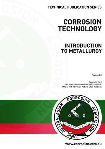
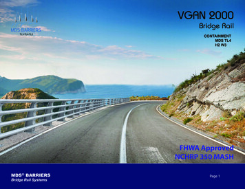
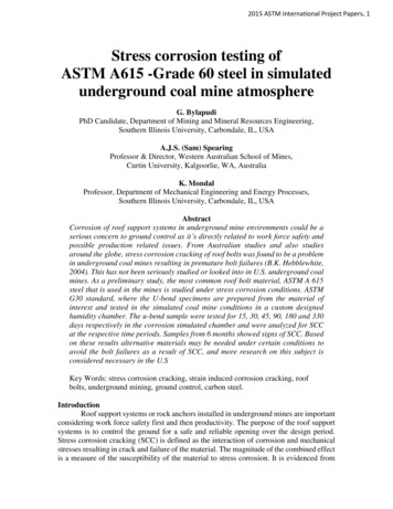
Corrosion GuidelinesMAY 2021Version 3.23.REQUIREMENTS FOR CONSULTANTS PROVIDING CORROSIONASSESSMENTS OF DEPARTMENT PROJECTSThis section outlines the roles and responsibilities of consultants providing corrosioninvestigation services and corrosion mitigation recommendations for Department projects.In addition, this section can be used by Department staff providing consultant oversight ofcorrosion investigation services and mitigation recommendations prepared by consultants.The flowchart at the end of this section outlines the roles and responsibilities of the variousDepartment functional groups assisting consultants performing corrosion investigationsand lists the responsibilities of the consultant.Foundation investigations are required for all structures (including bridges, tunnels,retaining walls, MSE walls, sound walls, ground anchor walls, sign structures,maintenance stations, pumping plants/stations, toll plazas, culverts, etc.). All foundationinvestigations require a corrosion investigation and evaluation. Preliminary and finalFoundation Reports prepared by consultants should include all available corrosion data forthe site and a brief discussion of the data. If corrosion data is not available or isinsufficient to provide conclusive information regarding the corrosivity of the site, thenadditional corrosion sampling and testing is required per Department guidelines during thefield investigation phases. If corrosion data can still not be obtained, then the site shouldbe assumed to be corrosive and corrosion mitigation required. In such cases it isrecommended that the Corrosion Branch be consulted.Consultants should follow the recommendations for preparing reports as discussed in thefollowing documents (see References): Caltrans Geotechnical Manual, Guidelines forPreparing Geotechnical Design Reports Version 1.3 (December 2006) and theFoundation Reports for Bridges document (dated March 2018).Consultants under contract to provide design related recommendations should includecorrosion recommendations consistent with Department guidelines. Corrosion designrecommendations should be based on the worst case test results from the site in accordancewith Department guidelines. Sufficient information regarding the number and location ofsoil borings, sampling, and testing should be included to allow a thorough review of anycorrosion recommendations by Department staff.Corrosion testing of soil (both surface and subsurface soil samples) and water samples shallbe performed in accordance with the applicable California Test (CT) (see References). Ifprocedures and equipment other than those specified in the applicable CT are used, thosevariations must be approved, documented, and presented with the corrosion test results.References to the test methods used for corrosion testing must be included on each pagethat presents the corrosion test results and analysis. Some variations (like a one-pointresistivity test instead of a minimum resistivity test) will not be allowed. If in doubt aboutwhether alternative test methods are acceptable or not, contact the Corrosion Branch ofMETS before starting any testing.3-1
Corrosion GuidelinesMAY 2021Version 3.2Minimum resistivity and pH tests are outlined in CT 643 (see References). Test proceduresfor determining water-soluble sulfate and chloride contents are outlined in CT 417 and CT422 (see References). Consultants should follow the guidelines presented in this documentfor performing corrosion assessments of project sites when performing work for theDepartment.The Corrosion Branch of METS is available to review all corrosion investigationsconducted by consultants, should additional assistance be needed. Upon request from thefunctional groups performing oversight, the Corrosion Branch will comment on thecorrosion aspects of Materials Reports, Geotechnical Design Reports, Foundation Reports,and Preliminary Reports prepared by consultants.3-2
Corrosion GuidelinesMAY 2021Version 3.23-3
Corrosion GuidelinesMAY 2021Version 3.24.CORROSION BASICSCorrosion is the deterioration of a metal through a reaction with its environment.Typically, corrosion involves contact of the metal with moisture and air (oxygen). Thedeterioration that takes place during the corrosion process is the basic tendency of the metalto revert to its natural state prior to it being developed from its primary ore material. Themost common example of corrosion is the rusting of steel into iron oxide, its primary ore asfound in the earth.The corrosion process of metals is an electrochemical process involving a transfer ofelectrons from the metal’s surface to ions in the environment (the electrolyte).Corrosion is often described in electrical terms as an electrical circuit consisting of four keycomponents. These include an anode (where corrosion or chemical oxidation reactions aretaking place), a cathode (where chemical reduction reactions are taking place), anelectrolyte (solutions or conductive media providing the supply of chemicals needed tosustain the cathodic reactions at or near the metal surface), and a metallic path.4.1 Corrosion TermsThe anode is where corrosion or chemical oxidation reactions are taking place. These arethe locations on the metal surface where electrical current is being passed by chemicalmeans from the metals surface to ions, elements, or compounds in the electrolyte. Themetal is losing electrons and combining with other elements in the environments by meansof an oxidation reaction.The cathode is where chemical reduction reactions are taking place. These are thelocations on the metal surface where electrical current is being passed by chemical meansfrom ions, elements, or compounds in the electrolyte to the surface of the metal. Thischemical reaction is a reduction reaction.ANODEAn electrode where oxidation reactions(corrosion) occur.CATHODEAn electrode where reduction occurs.The anode and cathode in a corrosion process may be on two different metals connectedtogether forming a bimetallic couple, or as they may be on the same piece of metal. Anarea on a metal surface (or with two dissimilar metals, each respective metal) eitherbecomes an anode or a cathode depending on the electrical potential of one area relative tothe other. The electrical potential difference is the electromotive force of the cell and is thevoltage difference between the anode and cathode of the cell. In any electrochemical cell,the area that is more negative in potential will undergo corrosion if coupled to the morepositive area. The corrosion process is initiated by differences in the natural potentialbetween the two dissimilar metals (bimetallic couple); metallurgical variations in the state4-1
Corrosion GuidelinesMAY 2021Version 3.2at different points on the surface a single metal; or localized variations in the environmentsuch as variations in moisture content or oxygen concentration.The electrolyte is the material in contact with both the anode and the cathode that allowsions to migrate between the two electrodes. This allows ionic current flow to occurbetween the anode and the cathode. The electrolyte includes the source of atoms, elements,or compounds required for ionic current flow to and from the metal electrodes. Theelectrolyte is the environment that the metal is in contact with including whatever salts andliquids are present (e.g., soil for a buried metal or concrete for reinforcing steel).The metallic path completes the electrical circuit and allows electrons to flow from theanode to the cathode in the electrochemical cell.ELECTROLYTESoil and/or liquid or other conductivemedia adjacent to and in contact withthe anode and the cathode that allowsions to migrate.METALLIC PATHAny conductor that allows electrons to flow.4.2 Electrochemical EquationsThe corrosion process can be described through a series of anodic and cathodic reactionequations (electrochemical equations) depending on the metal and ionic species involved.Mo(metal)M n ne(ion) (electron)Where Mo represents a metal atom such as iron in a metallic structure; thearrow indicates the direction that reaction is occurring; the symbol M represents a metalion; and n along with ne- indicates the number of electrons involved in the chemicalreaction.A common example is that of iron corrosion:At the anode, iron is oxidized to the ferrous state, releasing electrons.Fe(iron)Fe 2e(iron ion) (2 electrons)Iron gives up two electrons, which pass through the metal from an anodic site to a cathodicsite where they are consumed in a cathodic (reduction) reaction. The cathodic reaction is inthe form:R eRo(ion) (electron)(reduced species)Where R represents a positive ion in solution, e- indicates the number of electrons gained,the arrow indicates the direction that reaction is occurring; and Ro is the reduced atomproduced as a result of the chemical reaction.4-2
Corrosion GuidelinesMAY 2021Version 3.2Two common examples of cathodic reactions are the reduction of hydrogen and oxygen:2H 2e(hydrogen ions in solution) (electron)O2(oxygen in solution) 2H2O (water)H2(reduced species) 4e (electrons)4OH(reduced species)4.3 Electromotive Force Series and Galvanic SeriesFrom the previous discussion, there is a transfer of electrons that occurs during the corrosionprocess. The example shown was that of steel in the presence of hydrogen and oxygen (bothpresent as dissolved species in water). Similar electrochemical reactions can occur regardlessof the conductive contact medium (soil, water, concrete, etc.). The standard that has beenestablished to provide a reference scale of electrical potential values for metals and non-metalsis known as the electromotive force (EMF) series or REDOX potential series.Another useful series is the galvanic series. The galvanic series is the electrical potential ofa metal or alloy in a particular electrolytic solution (usually seawater). It is useful indetermining how two or more metals will behave if electrically connected in an ionicallyconductive environment. The electrical potential of each metal is measured as beforeagainst a standard. A reference electrode is simply an electrode (electrical conductor) thathas a stable and well know electrical potential. The high stability of the electrode potentialis usually reached by employing a redox system with constant (buffered or saturated)concentrations of each participant of the redox reactions.Examples of reference electrodes are the copper/copper sulfate (Cu/CuSO4) referenceelectrode, saturated calomel electrode (SCE) reference, and the silver/silver chloride(Ag/AgCl) reference electrode.In terms of corrosion, when looking at metals in an electrical potential series such as anelectrical motive force series or a galvanic series, when two metals are coupled together,the more negative metal (the anodic metal) will corrode relative to the more cathodic(noble) metal.4-3
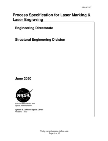
Corrosion GuidelinesMAY 2021Version 3.25.PRINCIPLES OF CATHODIC PROTECTIONCathodic protection (CP) is an electrochemical technique used to control corrosion. CPprovides a method to minimize deterioration of a metal (or structure) due to corrosion thatis occurring as a result of contact with the surrounding environment (electrolyte).Degradation is minimized by reversing the natural electrical current flow that is occurringduring the corrosion process.CP is achieved by connecting an external anode to the metal to be protected and allowing adirect current (DC) electric current to pass from that anode to the metal (the cathode)sufficient enough to keep all areas of the metal from corroding.When electrical current can flow from the external anode in sufficient quantity to protectall areas of the metal simply by the natural difference in electrical potential between theanode and cathode, the cathodic protection system is referred to as a galvanic CP system.When an external DC power source is needed to increase the electrical current flow to thecathode to a level that sufficiently protects all areas of the metal in question, the system iscalled an impressed current CP system.5.1 Galvanic CP SystemsGalvanic CP systems use reactive metals or alloys as anodes that are connected to the metalbeing protected. Active metals commonly used include zinc, aluminum, and magnesiumalloys. Alloys may include combinations of these metals along with slight additions ofminor elements to improve the alloys stability characteristics. With Galvanic CP systems,the sacrificial anode material is connected directly to the structure (metal) that requirescorrosion protection. Coupling the two materials (the anode and the metal of the structure)will cause a shift in electrical potential of the structure metal since the structure metal isnow the artificial “cathode” in the anode-cathode circuit and the bimetallic couple will tryand reach an equilibrium potential. Contact to the reinforcement is made either bymetallizing directly over the exposed reinforcement or by attaching a stud to thereinforcement when patching is needed for structural reasons. The zinc is then metallizedover the exposed stud.5.2 Impressed Current CP SystemsImpressed current CP systems typically consist of a power source to drive the protectiveCP current, and an anode material that is relatively inert or that has a low dissolution rate.Impressed current CP systems are installed such that that the anode does not directlycontact the metal or structure being protected. The anode is connected to the positive sideof the DC power supply, and the metal being protected is connected to the negative side ofthe power supply. The “circuit” is completed through the electrolytic path of soil orconcrete that separates the anode and cathode. This resistive path is needed so that a direct5-1
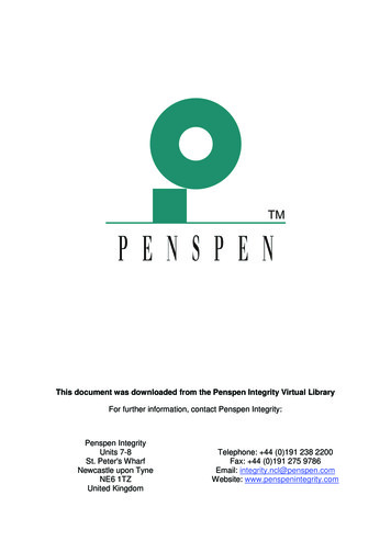
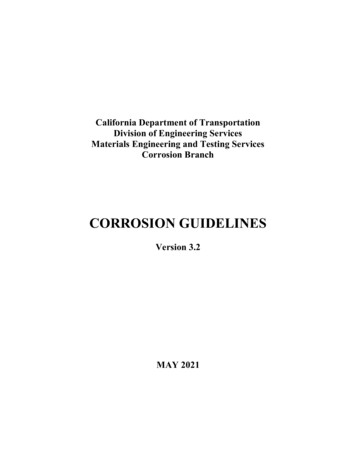
Corrosion GuidelinesMAY 2021Version 3.2electrical short circuit does not occur between the negative and positive leads of the powersupply. Figure 5.2-1 shows a schematic of an impressed current CP system for reinforcedconcrete. The battery symbol represents the DC power source. The positive side of thesource is connected to a titanium anode mesh. The negative side of the source is connectedto reinforcement in concrete. The concrete has been omitted from the view.Figure 5.2-1: Schematic of an impressed current CP system for reinforcedconcrete. The battery symbol represents the DC power source. The positive sideof the source is connected to a titanium anode mesh. The negative side of thesource is connected to reinforcement in concrete. The concrete has beenomitted from the view.5.3 Galvanic AnodesCaltrans Construction has made use of galvanic CP anodes designed by BASF, EuclidChemical Company, Sika Corporation and Vector Technologies for bridge expansions andrepairs where new concrete is being placed in contact with older concrete. These productsconsist of a casing surrounding a zinc core protecting the core from damage during placementand after placement. The casing provides an environment to sustain the zinc core. It does thisby modulating the pH to prevent swings that might consume the core at a greater rate. Thecasing also prevents any carbonation and prevents passivation of the zinc core. Passivation isa thin film of zinc oxide that forms on the zinc surface rendering it inactive. To overcomepassivation, the zinc core is embedded in an active matrix (casing) which typically raises thepH to approx. 14.5 to prevent passivation.5-2
Corrosion GuidelinesMAY 2021Version 3.2The anodes are tied directly to the reinforcing steel. The number of anodes are selectedbased on knowing the steel density ratio (surface area of steel/surface area of concrete)within the zone requiring protection, and recommended maximum spacing requirements forparticular product can be attained from the manufacturer. The spacing requirements shouldnot be exceeded. Recommended spacing requirements are based on research indicating thata current density requirement between 0.5 and 0.2 microamps per cm² of steel surface areais needed to provide some corrosion protection benefit in concrete.5-3
Corrosion GuidelinesMAY 2021Version 3.26.CORROSIVE ENVIRONMENTThe Department has adopted the American Association of State Highway TransportationOfficials (AASHTO) Load and Resistance Factor Design (LRFD) Bridge Specificationrequirement for a 75-year structure design life. However, culverts and drainage facilitiestypically require a 50-year maintenance free design life. Table 5.10.1-1 MinimumConcrete Cover to Reinforcement (in.) for 75-year Design Life of Section 5.10.1 (seeReferences) Section 5 Concrete Structures of California Amendments (to the AASHTOLRFD Bridge Design Specifications)) provides the four exposure conditions found inCalifornia.A. Non-Corrosive – soils and waters that are not corrosive to metals or concrete and donot meet the requirements in Section 6.1 below for a corrosive site.B. Non-Marine – Soils and waters that meet the requirements stated below in Section6.1 for a corrosive site and not within 1000 feet of a marine surface body of water.This exposure describes the soil above and extending down to 3 feet below thecurrent lowest ground water elevation or 3 feet below the lowest recorded/measuredground water elevation. This also applies to corrosive ground water.C. Marinea. Atmosphere – Structural elements exposed to the atmosphere over landwithin 1000 ft of ocean or marine water and the atmosphere above thesplash zone. Marine water, from corrosion considerations, is any body ofwater having a chloride content greater than or equal to 500 ppm.b. Water Permanently Below MLLW Level – Structural elements permanentlyimmersed 3 ft below the Mean Lower Low Water (MLLW) elevation.c. Splash Zone – Structural elements exposed to marine water extending from3 ft below the MLLW to 20 ft above the Mean Higher High Water(MHHW) elevation and 20 ft from the edge of water at the MHHW.D. Freeze/Thaw - Structural elements exposed directly to freezing/thawing cycles andor de-icing salts, snow run-off or snow blower spray.Site specific corrosion investigations are needed to determine the corrosivity of a site andto provide appropriate corrosion mitigation measures to obtain the desired design lives.Some of the factors that contribute to corrosion include the presence of soluble salts in soiland water, pH, the presence of oxygen industrial contamination and microbial activity.6.1 The Department's Definition of a Corrosive EnvironmentCorrosion of metals is an electrochemical process involving oxidation (anodic) andreduction (cathodic) reactions on metal surfaces. For metals in soil or water, corrosionother than galvanic between two metals, is typically a result of contact with soluble saltsfound in the soil or water or atmosphere. This process requires moisture to form solutions6-1
Corrosion GuidelinesMAY 2021Version 3
CORROSION BASICS . sound walls, sign structures, buildings, pump stations, groundwater studies, erosion control features, sub-excavation, and any other studies involving engineering geology. As part of the geotechnical investigation, . Engineering Services (DES) desi