Transcription
- 31NASA Technical Memorandum 83774Monolithic Microwave IntegratedCircuits—Interconnections andPackaging ConsiderationsK. B. Bhasin, A. N. Downey, G. E. Ponchak,R. R. Romanofsky, G. Anzic, and D. J. ConnollyLewis Research CenterCleveland, OhioPrepared for theFourth Annual International Electronics Packaging Conferencesponsored by The International Electronics Packaging SocietyBaltimore, Maryland, October 29-31, 1984NASA
MONOLITHIC MICROWAVE INTEGRATED CIRCUITS - INTERCONNECTIONS ANDPACKAGING CONSIDERATIONSK. B. Bhasln 1 , A. N. Downey, G. E. Ponchak, R. R. Romanofsky,G. Anzlc, and D. J. ConnollyNational Aeronautics and Space AdministrationLewis Research CenterCleveland, Ohio 44135SUMMARYMonolithic Microwave Integrated Circuits (MMIC's) above 18 GHz are beingdeveloped because of Important potential system benefits 1n the areas of cost,reliability, reprodudblHty, and control of circuit parameters. It 1s Important to develop Interconnection and packaging techniques that do not compromisethese MMIC virtues. In this paper, currently available microwave transmissionmedia are evaluated to determine their suitability for MMIC Interconnections.An antipodal finllne type of mlcrostrlp to waveguide transition's performance1s presented. Packaging requirements for MMIC's are discussed 1n terms ofthermal, mechanical, and electrical parameters for optimum desired performance.INTRODUCTIONAdvances 1n GaAs high frequency devices and materials technology (ref. 1)are making monolithic Integration of microwave circuitry a possibility. GaAsmonolithic microwave Integrated circuits (ref. 2) (MMIC's) operating at highfrequencies (Ku band and above) are showing promise for future space communications applications (ref. 3). The lightweight, small size, and high reliabilityof MMIC's (ref. 4) make them candidates to enable superior space communicationssystems. The application of MMIC's 1n space communications systems requiresthe development of transmit and receive modules for phased array antenna systems (ref. 5). In order to take full advantage of MMIC characteristics, thepackaging and Interconnection of MMIC's for Integration at these frequenciesrequires numerous considerations. Low RF signal loss, wide bandwidth performance, manufacturabHUy, and reliability are a few of them.Characteristics of MMIC's which Influence Interconnections and packagingdesign, materials and fabrication requirements are described by presentingexamples of MMIC's under development. For the RF Input/output connections ofMMIC's, a Van-Heuven type mlcrostrlp to waveguide transition which providesease of MMIC Integration for testing and packaging was chosen for detailedanalysis. Improvements which have been obtained 1n the performance of thistransition by modification 1n design and materials are discussed. Expecteddifficulties 1n obtaining maximum performance due to the high frequency ofMMIC's are outlined. Based on available technology, packaging concepts arepresented.]NASA Resident Research Associate with the University of Cincinnati,Dept. of Electrical and Computer Engineering, Cincinnati, Ohio.
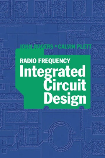
MONOLITHIC MICROWAVE INTEGRATED CIRCUITSA prototype MMIC 1s Illustrated 1n figure 1. Monolithic microwave Integrated circuits (MMIC's) are mainly being fabricated on GaAs semi-Insulatingsubstrates. The monolithic approach allows the elimination of wire bonds(except for dc bias) used In hybrid microwave Integrated circuits. The highdielectric constant (-13.0) of GaAs allows the fabrication of mlcrostrlp transmission line structures with small dimensions, facilitating the Integration ofvarious active and passive components on the same substrate. The high resistivity of a GaAs substrate allows the fabrication of active devices by epitaxial deposition of a doped layer or by an 1on Implantation process. The GaAsMESFET 1s the most used active device. Capacitors are formed using either1nterd1g1tal or Metal-Insulator-Metal (MIM) structures, while resistors areformed using thin films of metals such as Cr, T1, Ta, or cermets such as TaN(ref. 4). The various active and passive elements which form monolithic Integrated circuits can be seen 1n figure 2. The circuit 1s designed to operateat frequencies of 27.5 to 30 GHz and 1s an amplifier circuit for a receivermodule. The circuit was designed and developed by Hughes Aircraft Company .under contract from NASA-Lewis Research Center (ref. 3).The circuit shown 1n figure 1 1s a transmit module which 1s being developed by Rockwell International for NASA-Lewis Research Center (ref. 3). Themicrowave Input and output connections are 50 ohm mlcrostrlp transmission linestructures rather than simple pads. Also, dc connections are noticeable aspads on the top of the MMIC chip. The chip size 1s 4.8 mm by 6.4 mm. This isthe Initial design layout and Includes diagnostic test circuitry. The finallayout could produce a smaller chip size. The module consists of five cascaded-single bit phase shifters, digital control circuitry, a two-stage buffer amplifier and a three-stage power amplifier. The typical RF power output 1s expected to be above 200 mW 1n the 17.7 to 20.2 GHz frequency range with gain of16 db.,'. This chip will require both RF input/output and dc connections to the circuit as is shown in figure 1. This combination of RF/dc connections to thesame chip is what makes packaging designs of MMIC's more difficult than forconventional IC's. In addition to the direct connections to the chip, a meansof coupling the RF Input (output) from the waveguide efficiently over theproper bandwidth to the mlcrostrlp must also be considered 1n any packagingscheme 1f the advantages of MMIC's are to be preserved.MMIC INTERCONNECTIONSThe dc biasing lines of MMIC's are routinely brought out to a pad on theside of a chip where a wire bond can be made to the pad, or a commonly available bus termination with pins for connections to the pads can be used for dcbiasing. The RF Input/output lines of microwave devices require much more complicated structures. Fifty ohm matched mlcrostrlp transmission lines are thewidely adopted structure for MMIC RF Input/outputs. The integration of theMMIC Into the rest of the system requires an Interconnection between the microstrip of the MMIC and the external transmission media, which is relativelytransparent to the microwave signal. Characteristics of the interconnectionused must Include the following requirements:
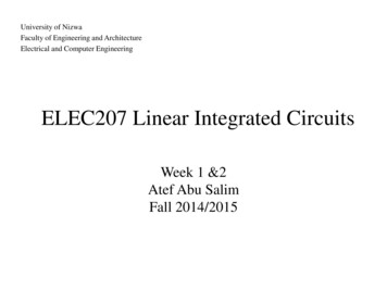
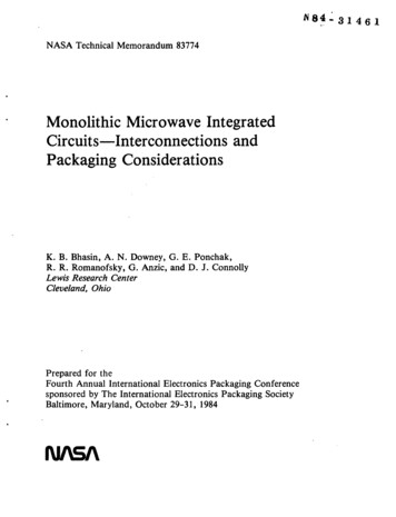
1. Low Insertion loss2. Wide bandwidth3. ReprodudblHty4. Ease of bondabllUy5. RF match6. Small sizeTransmission media which have been proposed for use at the frequencyranges being considered are shown 1n figure 3. The characteristics of thesetransmission media are summarized 1n Table I. From the table 1t can be seenthat mlcrostrlp and coplanar transmission lines have several characteristicswhich are desirable for MMIC Interconnections. Coplanar structures have theground plane on the same side of the substrate as the transmission line, buthave higher losses than mlcrostrlp structures.Based on currently available technology, the mlcrostrlp transmission line1s the structure most widely used (ref. 6) for the microwave frequencies since1t possesses a wide bandwidth, small geometric sizes, and relative ease ofInterconnection to module components. In addition, mlcrostrlp structures areeasily made by printed circuit board techniques on a wide variety of substrates. The disadvantages of a mlcrostrlp 1s Its high loss relative to someof the other structures. For that reason, a waveguide 1s commonly used as atransmission structure for Interconnection of devices separated by more thanshort distances. In addition waveguide 1s almost always used for Interconnection to test equipment above 18 GHz. Therefore, a means of coupling the microstrip energy to waveguide energy must be Included 1n the module design.Several mlcrostrlp to waveguide transitions have been Investigated. Basically there are three types of transitions: The first 1s a probe type (ref. 7)1n which the mlcrostrlp 1s outside the waveguide and an antenna like probecouples energy to the mlcrostrlp. Another type 1s the Van-Heuven type transition (ref. 8) 1n which the mlcrostrlp 1s placed 1n the center (E-plane) of thewaveguide on a printed circuit and a complex flnllne type structure couplesthe waveguide energy to mlcrostrlp energy. The third type of structure Incorporates mlcrostrlp on one of the waveguide walls 1n the H-plane and an E-planestructure couples the energy to 1t. Examples of such structures are cosinetapers (ref. 9) and stepped ridged transitions (ref. 10). Figure 4 shows thefour transitions.Van-Heuven Mlcrostrlp to Waveguide TransitionThe transition proposed by Van-Heuven, and later modified by many others(refs. 9 and 12) as shown 1n figure 5, offers many advantages over the othertypes. Host Important for packaging of MMIC chips 1n large numbers for use 1ncomplete systems, these transitions are 1n line with the waveguide making 1thighly suitable for system Integration, are easily fabricated using low costprinted circuit board techniques, and are tunable 1n these characteristics bychanging geometric parameters. Therefore, the Van-Heuven type transitionshave been chosen for a detailed analysis since they seem to offer the bestchoice for packaging and testing of MMIC chips.The effects of design and material parameters for this transition werestudied 1n detail. For testing, transitions were fabricated on copper-clad
Teflon type substrate material. Transitions were then tested 1n the test fixture shown 1n figure 6 by reflection and transmission measurements. It wasshown that the shape of the curved position and the geometric lengths of thetransition controlled the characteristics of the transition. Therefore, bychanging the geometric parameters of the transition, the bandwidth and degreeof flatness over the bandwidth could be controlled.The loss of the transition was determined to depend on both the shape ofthe transition and on Inherent mlcrostrlp properties. Figure 7 shows the effects of varying design parameters on the characteristics of the transition.By tuning for the lowest Insertion loss, a transition was designed which had0.9 db of loss for two back-to-back transitions connected by 2 1n of microstrip. By tuning for the widest bandwidth, for two back-to-back transitionsconnected by 2 1n of mlcrostrlp an Insertion loss of 1.25 db with a ripple of 0.1 db over the frequency band of 26.5 to 40 GHz was obtained. (This circuitwas not made on the optimal substrate material for lowest loss).A theoretical analysis was carried out to determine the source of thelosses observed. These losses were attributed to the mlcrostrlp structureItself and mismatching. Mlcrostrlp losses were due to conductor loss (ac),dielectric loss (a ) and radiation loss (ar). The total mlcrostrlp loss (ay)1s then given by:oq- ac tt(j arAs the frequency Increases above K-band, conductor losses tend to dominate. Dielectric loss 1s proportional to the dielectric dissipation factor(tan 6) of the material (see Table II). It 1s typically small compared to acfor ceramic substrates, but 1t 1s quite significant for polymeric substrates.The calculated losses (ref. 13) for Teflon type substrates with no Interfadalroughness were:ac 0.32 dB at 30 GHzad 0.27 dB at 30 GHzThe radiation losses were Ignored as the mlcrostrlp 1s 1n a shielded environment. Thus, a 0.53 dB loss 1s associated with the mlcrostrlp section of thetransition.Further experimental Investigation of mlcrostrlps were carried out todetermine the effect of the material properties on the Insertion loss. Seriessymmetrical gap resonator pairs (ref. 6) were constructed using unshieldedmlcrostrlps on several Teflon-type substrates. Using an automatic vector network analyzer, data on loss and dispersion (variation of phase velocity withfrequency) was taken to 20 GHz. The mlcrostrlp loss was obtained from theQ-factor measurements as determined by the resonant line center frequency and3 dB bandwidth. Table II provides a summary of experimental results as wellas published data on various substrate materials (refs. 14 and 15) commonlyused at these frequencies. The mlcrostrlp loss 1s slightly higher for Teflonsubstrates than for ceramics. This 1s due 1n part to the higher dissipationfactor (tan 6) of Teflon substrates and also because of their higher surfaceroughness (ref. 16). It 1s also apparent that the ceramic type substrates tendto be more dispersive than Teflon types (due to higher dielectric constants).
The preliminary analysis of the Van-Heuven mlcrostrlp to waveguide transition has shown that Improvements 1n design and materials can reduce losses tocreate a low loss transition.MMIC PACKAGINGAs presented earlier, the conventional packages used for IC's will not besuitable for MMIC packaging. Self-resonances (ref. 17) RF Insertion loss, andmismatching are some of the problems encountered with the conventional packages. Additionally, there are problems associated with high frequency operation. The following considerations must be taken Into account to develop MMICpackages.1.2.3.4.5.6.EnvironmentThermal managementMechanicalInsertion lossImpedance matchingEase of bondablHtyThe ceramic chip carrier (ref. 18) will be a likely candidate to provide hermetic sealing and bondab1!1ty to the mlcrostrlp. The chip carrier and Itspackaging Into complete transmit/receive module 1s described below.MMIC Chip CarrierAn Ideal MMIC chip carrier must minimize parasltlcs to obtain maximum performance of the MMIC. A schematic diagram of a MMIC chip 1s shown 1n figure 8.The ceramic substrate on which GaAs 1s placed should be as close as possible toGaAs 1n dielectric constant to obtain matching between the width of the microstrip lines; sapphire and alumina are two good choices for use as a chip carrier. The Interior of the ceramic chip carrier must be metallized to minimizeself-resonances. The ground planes of the GaAs chip can be connected throughvia holes to the ceramic substrate. The mlcrostrlp Input/output Interconnection lines through the ceramic walls are also very critical. The seal ringbetween the mlcrostrlp and the metallized package wall Increases parasltlcs 1f1t 1s not properly designed. MMIC's will generate significant amounts ofpower. The thermal considerations will require that the ceramic chip carrierbe mounted on a substrate such as copper-clad Invar, which has the same coefficient of thermal expansion as certain ceramic substrates. Copper provides themedia for thermal dissipation and also can act as a ground plane. The substrate must also allow attachment to the transition.Chip Carrier/Module InterfaceThe m1crostr1p/wavegu1de transition can provide the Interconnections desired for packaging. Several packaging concepts based on this are discussed1n figure 9. The design concept 1s based on the Van-Heuven mlcrostrlp to waveguide transition.
The MMIC chip carrier mounted on a suitable substrate 1s attached to thebottom piece of the T/R module shown 1n figure 9. The Input/output of thefinllne are attached to the mlcrostrlp of the chip carrier via the ribbon bondIng process.Another type of packaging design 1s based on the probe type of couplingwhich Hughes Aircraft Co. has demonstrated 1n testing. The MMIC chip carrier1s attached to the mlcrostrlp and energy 1s coupled via probe to waveguides.The chip carrier can be Integrated 1n the middle of the Input/output waveguideconnections. Developments 1n m1crostr1p-wavegu1de transitions are providing abase for various MMIC packaging schemes. High frequency aspects will put considerable demands on several packaging schemes.CONCLUSIONSGaAs monolithic microwave Integrated circuits, operating from 20 to40 GHz, are approaching the level where they can be considered for system Integration. Low cost Interconnections and packaging techniques are requiredwhich will preserve the advantages and characteristics of MMIC's.The requirements for MMIC Interconnections and packaging are significantlydifferent than conventional IC's. Mlcrostrlp to waveguide transitions can provide a convenient means to Interconnect MMIC's for testing and packaging.Van-Heuven type mlcrostrlp to waveguide transitions were designed andevaluated. Design modifications and Improvements 1n materials provided furtherIncreases 1n performance. Packaging concepts based on this transition thatallow MMIC's to be Integrated 1n the same plane were presented.The need for design knowledge at high frequencies for an MMIC packagewhich can meet various testability and 1ntegrab1l1ty criteria offer the mostchallenges. Novel approaches 1n Interconnection and packaging techniques maybe essential to take full advantage of MMIC's.REFERENCES1.J. V. Dllorenzo and D. D. Khandelwal, GaAs FET principles and technology.Artech House, 1982.2.L. C. Upadhyayula, M. Kumar and H. C. Huang, "GaAs MMICS Could Carry theWaves of the High-Volume Future," Microwave Systems News, July 1983, pp.58-82, vol. 13, no. 7.3.G. Anzlc, T. J. Kascak, A. N. Downey, D. C. L1u, and D. J. Connolly,"Microwave Monolithic Integrated Circuit Development for Future SpacebornePhased Array Antennas," Communication Satellite Systems Conference. 10th,Orlando, Florida, March, 1984. (AIAA Paper 84-0656).4.R. A. Pucel, "Design Considerations for Monolithic Microwave Circuits,"IEEE Transactions on Microwave Theory and Techniques, June 1981,pp. 513-534, vol. MTT-29, no. 6.
5.B. J. Edward, "Integration of Monolithic Microwave Integrated CircuitsInto Phased Array Antenna Systems," Proceedings of the 1983 AntennaApplications Symposium. Electromagnetic Lab. University of Illinois,Urbanna, Illinois.6.T. C. Edwards, Foundations for Mlcrostrlp Circuit Design. John Wiley andSons, 1981.7.E. T. Watklns, "GaAs FET Amp Uses One-Quarter Micron Gate, Heralding MICOpportunities at up to 60 GHz," Microwave Systems News, Dec. 1983, pp. 52to 62, vol. 13, no. 13.8.J. H. C. Van Heuven, "A New Integrated Wavegu1de-M1crostr1p Transition,"IEEE Transactions on Microwave Theory and Techniques, Mar. 1976,pp. 144-146, vol. MTT-24, no. 3.9.D. Rubin and D. Sanl, "mm Wave MICs use low value dielectric substrates,"Microwave Journal, Nov. 1976, pp. 35-39, vol. 19.10. S. S. Moochalla and C. An, "Ridge Waveguide used 1n mlcrostrlptransition," Microwaves and RF, Mar. 1984, pp. 149-152, vol. 23.11.D. Rubin and D. L. Sahl, "The Mlcrostrlp Dlplexer - A new tool forMillimeter Waves," June 1980, pp. 55-57, vol. 23.12. M. Dydyk and B. D. Moore, "Shielded Mlcrostrlp Aids V-Band ReceiverDesigns," Microwaves, Mar. 1982, pp. 77-82, vol. 21.13. K. C. Gupta, R. Garg and R. Chadhar, Computer-A1ded Design of MicrowaveCircuits. Artech House, 1981.14. A. Goplnath, R. Horton, and B. Easter, "Mlcrostrlp Loss Calculations,"Electronics Letters, Jan. 22, 1970, pp. 40-41, vol. 6, no. 2.15. J. H. C. Van Heuven, "Conduction and Radiation Losses 1n Mlcrostrlp,"IEEE Transactions on Microwave Theory and Techniques, Sept. 1974, pp.841-844, vol. 22, no. 9.16. K. B. Bhasln, D. C. L1u and R. R. Romanofsky, "Effect of Interfadalcharacteristics of Metal clad-polymerlc Substrates on High FrequencyInterconnection Performance," to be presented at the Materials ResearchSociety Meeting, Boston, Mass., Nov. 1984.17. Y. Hlrachl, Y. Takeuchl, M. Igarashl, K. Kosemura, and S. Yamamoto, "APackaged 20 GHz 1-W MESFET with a Novel V1a-Hole Plated Heat SinkStructure," IEEE Transactions on Microwave Theory and Techniques, Mar.1984, pp. 309-316, vol. MTT-32, no. 3.18. F. J. Dance, "Interconnecting Chip Carriers: A Review," CircuitsManufacturing, 1983, pp. 60-70, vol. 23.19. J. L. Zemany and W. J. SooHoo, "Packaging of a GaAs FET Solid StateAmplifier for a communication Satellite," Proceedings of the TechnicalConference, 3rd Annual International Electronic Packaging Conference,Itasca, IL, Oct. 24-26, 1983, pp. S1-S6.
TABLE I. - CHARACTERISTICS OF MICROWAVE/mm WAVE TRANSMISSION MEDIAType of uideLargeMicrostrip lineSmallCoplanar transmission line SmallFinlineModerateSuspended striplineModerateDielectric waveguideModerate(image line)Integrationto solidstate yEasyEasyEasyDifficult1000 and aboveSeveral hundredsSeveral hundredsSeveral hundredsSeveral hundreds1000 and aboveLargeLowLowLowLowModerateTABLE II. - REPORTED ELECTRICAL AND MECHANICAL CHARACTERISTICSSubstrate3131312520mil Cu Flonmil Cu Clad 217mil RT/Duroid 5880mil Fused Silicamil Alumina(99.5 percent)20 mil SapphireaRa 0.4Relative RF loss atDispersionSurfaceroughness,dielectric 106 Hz,constantdB/xymEr at Er at10 GHz 20 1.923.107.051.882.001.953.167.57.48.0Tan s0.8 to 1.0 0.00045.8 to 1.2 .0009.8 to 1.2 .0009.03.0001 .4.00025.03 .0001Thermalconductivity,W/cm C-0.003 .003 .003.013.25.38
4.8 mm X6.4 mm X 0.127 mmD/A CONVERTER *INPUTTEST CIRCUITSPHASE SHIFTERSOUTPUT2 STAGE BUFFER ANDC-84-11393 STAGE FINAL AMPLIFIERFigure 1. - 20 GHz monolithic transmit module.0.94mmC-84-1140Figure 2. - 27.5 - 30 GHz monolithic low noise amplifier.
QUASI-OPTICALWAVEGUIDEIMAGE LINEiMICROSTRIP 1 J2 J 3COPLANAR WAVEGUIDE50100150I200250FREQUENCY, GHz300Figure 3. - Microwave/mm wave transmission media.350400
VAN HEUVEN(TOP VIEW)COSINE TAPER(SIDE VIEW)GROUND PLANE SIDEBRASS OR SIMILAR METALWAVEGUIDEDIELECTRIC MATERIAL, rMICROSTRIP SIDEAIR DIELECTRICRIDGED(SIDE VIEW)PROBE(FRONT VIEW)Figure 4. - Microstrip/waveguide transitions.MODIFIED van HEUVEN TRANSITIONvan HEUVEN TRANSITION(26.5-40 GHz)(26.5 - 40 GHz)FABRICATED ON COPPER CLAD TEFLON TYPE SUBSTRATESFigure 5. - Waveguide to microstrip transitions.
Figure 6. - 26.5 - 40 GHz waveguide to microstrip transition in test fixture.MODIFIED VAN HEUVEN TRANSITIONS 1l/linOVAN HEUVEN TRANSITION4026.5FREQUENCY, GHzFigure 7. - Insertion loss measurements. Note: above two insertion loss plots are fortwo back to back transitions with 2 in. of microstrip connnecting them.
-DC CONNECTIONMETALLIZEDCERAMIC — oaQDQQQiiaQRF INPUTMICROSTRIP--RF OUTPUT200x200CHIPDDDDD0\ -THERMALLYCONDUCTINGSUBSTRATETOP VIEWr MMIC CHIP TO BE MOUNTED.-7 METALLIZED CERAMIC—iSIDE VIEWFigure 8. - MMIC chip carrier.x -THERMALLYCONDUCTINGSUBSTRATE
BUSOoINPUTOQOUTPUToFigure 9. - Packaging concepts for MMIC's.OMMICCHIPCARRIER
2. Government Accession No.1. Report No.3. Recipient's Catalog No.NASA TM-837745. Report Date4. Title and SubtitleMonolithic Microwave Integrated Circuits Interconnections and Packaging Considerations6. Performing Organization Code506-58-228. Performing Organization Report No.7. Authors)K. B. Bhasin, A. N. Downey, G. E. Ponchak,R. R. Romanofsky, G. Anzic, and D. J. ConnollyE-226610. Work Unit No.9. Performing Organization Name and Address11. Contract or Grant No.National Aeronautics and Space AdministrationLewis Research CenterCleveland, Ohio 4413513. Type of Report and Period CoveredTechnical Memorandum12. Sponsoring Agency Name and AddressNational Aeronautics and Space AdministrationWashington, D.C. 2054614. Sponsoring Agency Code15. Supplementary NotesK. B. Bhasin, NASA Lewis Resident Research Associate and the University ofCincinnati, Dept. of Electrical and Computer Engineering, Cincinnati, Ohio; A. N.Downey, G. E. Ponchak, R. R. Romanofsky, G. Anzic, and D. J. Connolly, NASA LewisResearch Center. Prepared for the Fourth Annual International ElectronicsPackaging Conference sponsored by The International Electronics Packaging Society,Baltimore, Maryland, October 29-31, 1984.16. AbstractMonolithic Microwave Integrated Circuits (MMIC's) above 18 GHz are being developedbecause of important potential system benefits in the areas of cost, reliability,reproducibility, and control of circuit parameters. It is important to developinterconnection and packaging techniques that do not compromise these MMIC virtues.In this paper, currently available microwave transmission media are evaluated todetermine their suitability for MMIC interconnections. An antipodal finline typeof microstrip to waveguide transition's performance is presented. Packaging requirements for MMIC's are discussed in terms of thermal, mechanical, and electricalparameters for optimum desired performance.17. Key Words (Suggested by Author(s))18. Distribution StatementMonolithic microwave integrate circuits;Electronics interconnections and packagingtransmission line structures19. Security Classif. (ot this report)UnclassifiedUnclassified - unlimitedSTAR Category 3220. Security Classif. (of this page)21. No. of pagesUnclassified"For sale by the National Technical Information Service, Springfield, Virginia2216122. Price*
National Aeronautics andSpace AdministrationWashington, D.C.20546SPECIAL FOURTH CLASS MAILBOOKS.MAILOfficial BusinessPenalty 'or Private Use, 300NASAPottage and Fees PaidNational Aeronautics andSpace AdministrationNASA-451If Undfliverjhlt (Section ISM) No, Re urn
monolithic microwave Integrated circuits (ref. 2) (MMIC's) operating at high frequencies (Ku band and above) are showing promise for future space communica-tions applications (ref. 3). The lightweight, small size, and high reliability of MMIC's (ref. 4) make them ca