Transcription
AEDC-TR-73-5HANDBOOKUNCERTAINTY IN GAS TURBINE MEASUREMENTSDr. R. B. Abernethy et al.Pratt & Whitney AircraftandJ. W. Thompson, Jr.ARO, Inc.-February 1973--Approved for public release; distribution unlimited.ENGINE TEST FACILITYARNOLD ENGINEERING DEVELOPMENT CENTERAIR FORCE SYSTEMS COMMANDARNOLD AIR FORCE STA TION, TENNESSEEl'ROPEP:rv OF U.S. AIR FORCE.A.EDC TECI-IN1CAJ.J LffiRARYii P.r-.JOJr .-4cFB.rt 37389F'n:po j" t:;(,fL l' ;. ,i.,:' .\,"! 5.L'[' F'ores
NOTICBSWhen u. S. Government drawings specifications, or other data are used for any purpose other than adefinitely related Government procurement operation, the Government thereby incurs no responsibilitynor any obligation whatsoever, and the fact that the Government may have formulated, furnished, or inany way supplied the said drawings, specifications, or other data, is not to be regard d by implicationor otherwise, or in any manner licensing the holder or any other person or corporation, or conveyingany rights or permission to manufacture, use, or sell any patented invention that may in any way berelated thereto.Qualified users may obtain copies of this report from the Defense Documentation Center.References to named commercial products in this report are not to be considered in any sense as anendorsement of the product by the United States Air Force or the Government.
AEDC-TR-73-5HANDBOOKUNCERTAINTY IN GAS TURBINE MEASUREMENTSDr. R. B. Abernethy et al.Pratt & Wh itney AircraftandJ. W. Thompson, Jr.ARO, Inc.Approved for public release; distribution unlimited.AEDC Technical LibraryArnold AFB, TN, 37389
AEDC-TR-73-5FOREWORDThe work reported herein was sponsored by the Arnold Engineering DevelopmentCenter, Air Force Systems Command, United States Air Force, under Program Element65802F.The results presented were compiled by· ARO, Inc. (a subsidiary of Sverdrup &Parcel and Associates, Inc.), contract operator of the Arnold Engineering DevelopmentCenter (AEDC) , Air Force Systems Command (AFSC), Arnold Air Force. Station,Tennessee, under Contract F40600-73-C-0004. The preparation of the text wasaccomplished by Dr. R. B. Abernethy, Senior Project Engineer, Billy D. Powell, David L.Colbert, and Daniel G. Sanders, Pratt & Whitney Aircraft, under subcontract to ARO, Inc.The contracted work consisted of a revision to the material in the "Interagency ChemicalRocket Propulsion Group (ICRPG) Handbook for Estimating the Uncertainty inMeasurements made with Liquid Propellant Rocket Engine Systems," CPIA PublicationNo. 180 (same authors as above), substituting treatment of gas turbine measurementerrors for rocket engine treatment and writing additional material applicable to gasturbine measurement errors. The report was prepared under ARO Project No. RW5245,and the manuscript was submitted for publication on May 8, 1972.The authors are indebted to the many engineers and statisticians who havecontributed to the work. A few must be noted for their particular contributions, Dr.Joan Rosenblatt, Dr. H. H. Ku, and J. M. Cameron of the National Bureau of Standardsfor their helpful discussions and comments on both this handbook and CPIA 180, andsimilarly, R. E. Smith, Jr., Chief of T-Cells Division, as well as T. C. Austin, C. R.Bartlett, W.O. Boals, Jr., and T. J. Gillard of ARO, Inc., at the Arnold EngineeringDevelopment Center. Engineers at Pratt & Whitney Aircraft, Florida and Connecticutfacilities, provided the authors with constructive and spirited criticism in every section.Various technical committees under the American Society of Mechanical Engineers(ASME), the American Institute of Aeronautics and Astronautics, and the InternationalStandards Organizations expressed interest and comments.This technical report has been reviewed and is approved.EULES L. HIVELYResearch and Development DivisionDirectorate of TechnologyROBERT 0. DIETZDirector of Technologyii
ABSTRACTThe lack of a standard method for estimating the errors associated with gas turbineperformance data has made it impossible to compare measurement systems betweenfacilities, and there has been confusion over the interpretation of error analysis.Therefore, a standard uncertainty methodology is proposed in this Handbook. Themathematical uncertainty model presented is based on two components of measurementerror: the fixed (bias) error and the random (precision) error. The result of applying themodel is an estimate of the error in the measured performance parameter. Theuncertainty estimate is the interval about the measurement which is expected toencompass the true value. The propagation of error from basic measurements throughcalculated performance parameters is presented. Traceability of measurement back to theNational Bureau of Standards and associated error sources is reviewed.liii
AEDC-TR-73-5CONTENTSABSTRACT . , .INTRODUCTION1.1 Objective . .1.2 Scope . . . .1.3 Measurement Error1.3.1 Precision (Random Error)1.3.2 Bias (Fixed Error)1.3.2.1Large Known Biases1.3.2.2 Small Known Biases1.3.2.3Large Unknown Biases1.3.2.4 Small Biases, Unknown Sign, and Unknown Magnitude1.3.2.5 Small Biases, Known Sign, and Unknown Magnitude1.4 Measurement Uncertainty . . . . . .1.5 Propagation of Measurement Errors.1.5.1 Engine Inlet Airflow . . . . . . . . . . .1.5.2 Thrust Specific Fuel Consumption (TSFC) .1.6 Measurement Process1.7 Reporting Error . . . . .1.8 Traceability/"r./n. UNCERTAINTY MODEL2.1 General . . . . . . .2.2 Measurement Error Sources2.2.1 Calibration Hierarchy Errors2.2.2 Data Acquisition Errors2.2.3 Data Reduction Errors .2.3 Measurement Uncertainty Model2.4 Example of the Model . . . . .2.4.1 Net Thrust Measurement2.4.2 Fuel Flow Measurement2.4.3 Thrust Specific Fuel Consumption2.5 Summary . . . . . .III. FORCE MEASUREMENT . . . . . . .3.1 General . . . . . . . . . . . . . .3.2 Force Measurement Error Sources3.2.1 Force Transducer Calibration Hierarchy3.2.1.1Precision Index3.2.1.2 Degrees of Freedom3.2.1.3 Bias.3.2.1.4 Uncertainty.3.2.2 Data Acquisition and Reduction Errors3.2.2.1Applied Load Tests . . . . .3.2.2.2 Elemental Error Evaluation .3.2.2.2.1Stand 224242526292930303233333435363839
AEDC-TR-73-5III. FORCE MEASUREMENT (Continued)3.2.2.2.2Fuel Line Temperature Variations3.2.2.2.3Fuel Line Pressure Variations3.2.2.2.4Force Transducer Temperature andAmbient Pressure Variations.3.2.2.2.5Excitation Voltage Errors.3.2.2.2.6Recording System Electrical Calibration3.2.2.2.7Analog-to.Digital Conversion Errors3.2.2.2.8Recording System Resolution.3.2.2.2.9Electrical Noise.3.2.2.2.10 Tare Variations.3.2.2.2.11 Computer Resolution3.3 Force Measurement Error Analysis3.4 End-to.end Calibration . .3.5 Summary.IV. FUEL FLOW MEASUREMENT4.1 General . . . . . . . . . .4.2 Fuel Flow Measurement Error Sources4.2.1 Calibration Errors . . . . . . .4.2.1.1Volumetric Calibration.4.2.1.1.1Calibration of the Interlab Standard4.2.1.1.2Uncertainty in the Working Standard.4.2.1.2 Gravimetric Calibration4.2.1.3 Calibration by Comparison.4.2.2 Data Acquisition Errors4.2.2.1Multiple Instruments4.2.3 Data Reduction Errors . . . .4.2.3.1Density Determination Errors4.2.3.2 Computer Resolution4.3 Fuel Flow Measurement Errors4.4 End-to-end Calibration . . . . . . . . .4.5 Summary . . . . . . . . . . . . . . . .V. PRESSURE AND TEMPERATURE MEASUREMENTS5.1 General . . . . . . . . . . . . . . .5.2 Pressure Measurement Error Sources.5.2.1 Calibration Hierarchy Errors.5.2.2 Data Acquisition and Reduction Errors5.2.3 Probe Errors.5.2.4 Pressure Measurement Error Summary5.3 Temperature Measurement Error Sources5.3.1 Calibration Hierarchy Errors.5.3.2 Data Acquisition and Reduction Errors5.3.2.1Thermocouples.5.3.2.2 Resistance Thermometers.5.3.3 Temperature Measurement Error Summary5.3.3.1Thermocouples . . . . .5.3.3.2 Resistance Thermometers . . . 0717172737376777779798385878888929395979797
AEDC-TR-73-5VI. AIRFLOW . . . . . . . . . . . . . . . . . .6.1 General . . . . . . . . . . . . . . . . .6.2 Airflow Rate Measurement Techniques .6.2.1 Subsonic F10wmeters . . . . . .6.2.1.1Venturis and Nozzles6.2.1.2 Orifices . . . . .6.2.2 Critical Venturi Flowmeters . . .6.2.3 Calibration Techniques . . . . .6.2.3.1Calibration by Calculation6.2.3.2 Experimental Calibration6.2.3.3 Calibration by Fabrication6.3 Elemental Error Sources . . .6.3.1 Discharge Coefficient . . . . . . . .6.3.1.1Calculated Cd6.3.1.2 Experimentally Determined Cd6.3.1.2.1Comparison with a Standard Flowmeter6.3.1.2.2Calibration by Traverse. .6.3.1.2.3Calibration by Liquid6.3.1.2.4Calibration by Fabrication . . . . . .6.3.2 Non-Ideal Gas Behavior and Variation in Gas Compositions .6.3.3 Thermal Expansion Correction Factor . . . . . . .6.3.4 Ratio of Specific Heats and Compressibility Factor6.3.5 Measurement Systems6.4 Propagation of Error to Airflow6.4.1 Critical-Flow Venturi6.4.2 Subsonic OrificeVII. NET THRUST AND NET THRUST SPECIFIC FUEL CONSUMPTION7.1 General . . . . . . . . . . . . . . . . .7.2 Gross Thrust Measurement Techniques7.2.1 Scale Force Method7.2.2 Momentum Balance Method .7.3 Propagation of Errors to Net Thrust . .7.4 Propagation of Error to Net Thrust Specific Fuel Consumption .VIII. SPECIAL METHODS. . . . . . . . . . . . . . . . . . . . . . . . . .8.1 General . . . . . . . . . . . . . . . . . . . . . . . . . . . . . .8.2 Measurement Uncertainty for Multi-Engine Installations (Similar Engines)8.2.1 General . . . . . . . . . . . . . . . .8.2.2 Example of a Four-Engine Installation8.3 Measurement Processes . . . . . . . . . .8.3.1 Many Stand, -Many Engine Model8.3.2 Single Stand, Single Engine Model8.4 Confidence Interval when Biases are Negligible or can be Ignored .8.5 Compressor Efficiency Error Analysis8.5.1 General . . . . . . . . . . . . . . . . . . . . . . . . . . 11211511611611611 30131131132133133
AEDC-TR-73-5VIII. SPECIAL METHODS (Continued)8.5.2 The General Process . . . . . . . . . . .8.5.3 Single Stand, Single Compressor Process8.6 How to Interpret Uncertainty8.7 Dynamic Measureluent UncertaintyIX., GLOSSARY . . . . . . . . . . . . . . .APPENDIXESA. Precision Index for Uniform Distribution of ErrorB. Propagation of Errors by Taylor's Series . . . . . .C. Estimates of the Precision Index from Multiple MeasurementsD. Outlier DetectionE. T a b l e s . . . . . . . . . . . . . . . . . . . . . . . . . . . . . .1-41-51-61-71-8II-I11-211-311-411-5Measurement ErrorPrecision ErrorBias ErrorFive Types of Bias ErrorMeasurement Error (Bias, Precision, and Accuracy)Measurement Uncertainty, Symmetrical Bias .' .Measurement Uncertainty, Nonsymmetrical BiasFlow through a Choked Venturi . . . . .Force Measurement Calibration HierarchyData Acquisition System.Calibration Curve . . . . . . . . . . . . .Uncertainty Parameters, U (B t95 S)Overall Uncertainty Modela. General View . . . .b. Propagation of Errorc. Elemental ErrorsLogic Decision DiagramForce Measurement SystemForce Transducer Calibration HierarchyCalibration Curves.Scatter in Measured Force.Calibration Hierarchy Elemental BiasCalibration Process Uncertainty Parameter, U1 (B1 t95 Sl)Gas Turbine Thrust Measurement System Calibration Configuration .Precision Errors . . . . . . . . . . . . . . . . . .Temperature Bias Effect on Distribution of ErrorsAmbient Pressure Effect on Load Cell OutputErrorsa. Precision Error.b. Bias Error.c. Both Bias and Precision ErrorsElemental Precision Error of Calibration Power 922232323272930313233343940434345454547
AE -8VI-9VII-lVII-2Sensitivity Curve.Tare History Showing Elemental Precision ErrorTypical Calibration Data from Force Measuring SystemUsed in Engine Sea-Level Testing.Typical Calibration Data from Force Measuring SystemsUsed in Engine Altitude TestingTurbine Meter Signal.Turbine Meter Calibration Curve . . . . . . . . .Turbine Meter Volumetric Calibration HierarchyVolumetric Calibrator.Turbine Meter Gravimetric Calibration Hierarchy. . . . . . . .Gravimetric CalibratorTurbine Meter Comparison Calibration HierarchyComparative Calibration.Data Acquisition System CalibrationEnd-to-End Calibration . . . . . . .Strain-Gage Pressure Transducer CircuitryPressure Transducer Calibration with Pressure StandardDeadweight Piston Gage.Temperature Measurementa. Resistance Thermometer Three-Wire Systemb. Thermocouple SystemBossArrangementProbea. Front View.b. Side View.Pressure Transducer Calibration HierarchyDeadweight Piston Gage CalibrationPrecision Index at Any Applied Pressure (P)Periodic Pressure Tests.Temperature Transducer Calibration HierarchyTypical Thermocouple Channel.Temperature Data Recording CalibrationSchematic of Typical Venturi and Nozzle with Measuring StationsSchematic of Typical Orifice with Measuring StationsSchematic of Critical Venturi Flowmeter Installation Upstreamof a Turbine Engine.Discharge Coefficient Error DistributionCalibration by ComparisonFlowmeter Throat TraverseFlat. Mass-Velocity ProfileDistorted Mass-Velocity ProfileShaded Area Calculated as a Function of dl and d2Freebody Diagram for External Forces (Scale Force)Method of Determining Engine Gross (Jet) ThrustFreebody Diagram for Internal Forces (Momentum Balance).Method of Determining Engine Gross (Jet) 79798384889395100105106109110112113113114122123
lJncertaintyRun-to-Run DifferencesBias in a Random ProcessCorrelation Coefficients II.XXIV.Nonsymmetrical Bias Limits.lJncertainty Intervals Defined by Nonsymmetrical Bias LinnitsFlow Data.lJncertainty Components.Calibration Hierarchy Error SourcesData Acquisition Error SourcesData Reduction Error SourcesCalibration Hierarchy Error Sources.Calibration Data,Data Acquisition Error SourcesData Reduction Error SourcesForce easurement Elemental Error ValuesElemental Errors.International Practical Temperature Scale of 1968Elemental Error for Calibration by ComparisonAirflow easurement Error Source.Airflow Error Source . . . . . . . . . . . . . . . .Typical easurement and lJncertainty Values Qsed in Net Thrustfor Supersonic Afterburning Turbofan Engine .Derived easurement lJncertainty ValuesA easurement System with Six Error SourcesTabulation of the Elemental ErrorsSummary of Errors . . . . . . . . . .Elemental Errors.lJncertainty Values for Two 27131133134136136
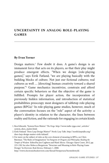
AE DC-T R-73-5SECTION IINTRODUCTION1.1 OBJECTIVEThe objective of this Handbook is to present a standard method of treatingmeasurement error! or uncertainty for gas turbine engine performance parameters, suchas thrust, airflow, and thrust specific fuel consumption. The need for a standard isobvious to those who have reviewed the numerous methods currently used. The subject iscomplex and involves both engineering and statistics. Only one method is presentedherein without alternative paths. A single standard method is required to makecomparisons between engine manufacturers and between facilities. However, it must berecognized that no single method will give a rigorous, scientifically correct answer for allsituations. Further, even for a single set of data, the task of finding and proving onemethod to be correct is usually impossible. The method selected is believed to be mostuniversally applicable. It is identical with the measurement uncertainty model used in therocket engine industry which has been well received ("ICRPG Handbook for Estimatingthe Uncertainty in Measurements made with Liquid Propellant Rocket Engine Systems,"CPIA No. 180, AD855l30, April 30, 1969).There are numerous examples for illustration. An effort has been made to use simpleprose with a minimum of jargon.1.2 SCOPEThis Handbook presents a working outline detailing and illustrating the techmquesfor estimating measurement uncertainty. Section II describes the mathematical model fora typical performance parameter (thrust specific fuel consumption). Sections III, IV, V,and VI treat errors associated with the measurement of force, fuel flow, pressure andtemperature, and airflow. Each section includes a discussion of the methods of calibrationand lists of the elemental errors and examples of the statistical techniques. Section VIIdescribes the calculations of the uncertainty in net thrust and thrust specific fuelconsumption at altitude conditions. Section VIII describes and illustrates several specialmethods. Section IX is the Glossary. Appendixes with tables, derivations, and proofs arefound at the end of the Handbook.1.3 MEASUREMENT ERRORAll measurements have measurementerrors. These errors are the differencesbetween the measurements and the truevalue defined by the National Bureau ofStandards (NBS). Uncertainty is the maximum error which might reasonably beexpected and is a measure of accuracy, Le.,the closeness of the measurement to the truevalue. Measurement error has two components: a fixed error and a random error.True (NBS) ValueMeasured ValueErrorI----4--.::---I------- ---- - I0.9800.9850.9901.0Fig. 1-1 Measurement Error! For a deftnition of terms used in this Handbook, see the Glossary in Section IX.10.995Parameter Measurement Value
AEDC-TR-73-51.3.1 Precision (Random Error)Random error is seen in repeated measurements. Measurements do not and are notexpected to agree exactly. There are always numerous small effects which causedisagreements. The variation between repeated measurements is called precision error. Thestandard deviation (a) is used as aAverage Measurementmeasure of the precision error. Alarge standard deviation meansScatter Due tolarge scatter in the measurements.Precision ErrorThe statistic (s) is calculated toestimate the standard deviation'Handis called the precision indexoi»Standard DeviationEstimate of aC)l:lQ)N50: Q)i lHI' i' - - 2(X. - X)1N- 1Par4meter Measurement ValueFig. 1-2 Precision Errorwhere N is the number of measurements made and X is the averagevalue of individual measurements Xi.1.3.2 Bias (Fixed Error)The second component, bias, is theconstant or systematic error. In repeatedmeasurements, each measurement has thesame bias. The bias cannot be determinedunless the measurements are comparedwith the true value of the quantitymeasured.;True (NBS) ValueAverage MeasurementI-"e---Bt as-.-.-tBias is categorized into five classes:(l) large known biases, (2) small knownbiases, (3) large unknown biases, andsmall unknown biases which may have(4) unknown sign ( ) or (5) known sign.Known Signand MagnitudeLarge(1) CalibratedOutParameter Measurement ValueFig. 1-3 Bias Errorpnknown Magnitude(3) Assumed to beEliminatedISmall(2) Negligible, (4) Unknown(5) KnownContributesSignSigntoBias LimitContributes toBias Limit2Fig. 1-4 Five Types of Bias Errors
AEDC-TR-73-51.3.2.1Large Known BiasesThe large known biases are eliminated by comparing the instrument with a standardinstrument and obtaining a correction. This process is called calibration.1.3.2.2 Small Known BiasesSmall known biases mayor may not be corrected depending on the difficulty of thecorrection and the magnitude of'the bias.1.3.2.3 Large Unknown BiasesUnknown biases are not correctable. That is, they may exist, but the magnitude of thebias is not known, and perhaps even the sign is not known.Every effort must be made to eliminate all large unknown biases. The introductionof such errors converts the controlled measurement process into an uncontrolledworthless effort. Large unknown biases usually come from human errors in dataprocessing, incorrect handling and installation of instrumentation, and unexpectedenvironmental disturbances such as shock and bad flow profiles. In a well-controlledmeasurement process, the assumption is that there are no large unknown biases. To ensurethat a controlled measurement process exists, all measurements should be monitored withstatistical quality control charts. A list of references describing the use of statisticalquality control charts is included at the end· of this section. Drifts, trends, andmovements leading to out-of-control situations should be identified and investigated.Histories of data from calibrations are required for effective control. It is assumedthroughout this Handbook that these precautions are observed and that the measurementprocess is in control; if not, the methods contained herein are invalid.1.3.2.4 Small Biases, Unknown Sign, and Unknown MagnitudeIn most cases, the bias error is equally likely to be plus or minus about themeasurement. That is, it is not known if the limit is positive or negative, and the estimatereflects this. The bias limit is estimated as an upper limit on the maximum fixed error.For example, 5 pounds IS a typical bias limit.It is both difficult and frustrating to estimate the limit of an unknown bias. Todetermine the exact bias in a measurement, it would be necessary to compare the truevalue and the measurements. This is almost always impossible. An effort must be made toobtain special tests or data that will provide bias information. The following are examplesof such data:1.Interlab, interfacility, intercompany tests on measurement devices, testrigs, and full-scale engines.2.Flight test data versus altitude test chamber data versus ground test data.3.Special comparisons of standards with instruments in the actual testenvironment.3
AEDC·TR·73-54.Ancillary or concomitant functions that provide the same performanceparameter; i.e., in an altitude engine test, airflow may be measured with(l) an orifice and (2) a bellmouth, (3) estimated from compressorspeed-flow rig data, (4) estimated from turbine flow parameter, and (5) jetnozzle calibrations.5.When it is known that a bias results from a particular cause, specialcalibrations may be performed allowing the cause to perturbate through itscomplete range to determine the range of bias.If there is no source of data for bias, the judgment of the most knowledgeableinstrumentation expert on the measurement must be used. However, without data, theupper limit on the largest possible bias error must reflect the lack of knowledge.1SmallKnown Sign, and Unknown MagnitudeSometimes the physics of the measurement system provide knowledge of. the signbut not the magnitude of the bias. For example, thermocouples radiate and conductenergy to indicate lower temperatures. The bias limits which result are nonsymmetrical,Le., not of the form b. They are of the form g where both limits may be positive ornegative or the limits may be of mixed sign as indicated. Table I below lists severalnonsymmetrical bias limits for illustration.Table I Nonsymmetrical Bias limitsBias Limits0,-5, 3,-8, 10 deg 15lb 7 psia-3 degExplanationThe bias will rangeThe bias will rangeThe bias will rangeThe bias will Tangefromfromfromfromzero to plus 10 deg.minus 5 to plus 15 lb.plus 3 to plus 7 psia.minus 8 to minus 3 deg.In summary, measurement systems are subject to two types of errors, bias andprecision error (Fig. 1-5). One sample standard deviation is used as the precision index.The bias limit is estimated as an upper limit on the maximum fixed error.1MEASUREMENT UNCERTAINTYFor simplicity of presentation a single number (some combination of bias andprecision) is needed to express a reasonable limit for error. The single number must havea simple interpretation (the largest error reasonably expected) and be useful withoutcomplex explanation. It is impossible to define a single rigorous statistic because the bias isan upper limit based on judgment which has unknown characteristics. Any function of thesetwo numbers must be a hybrid combination of an unknown quantity (bias) and a statistic(precision). However, the need for a single number to measure error is so great that theadoption of an arbitrary standard is warranted. The standard most widely used is4
AEDC-TR-73-5Average of AllMeasurementsTrue Value andAverage of AllMeasurements .t)s::(1)g.True Value(1)1-lrz.tParameter MeasurementParameter Measurementb. Biased, Precise, Inaccuratea. Unbiased, Precise, AccurateAverage of AllMeasurements. True Value andAverage of AllMeasurements' .t) g.True(1)1-lrz.tParameter MeasurementParameter Measurementd. Biased, Imprecise, Inaccuratec. Unbiased, Imprecise, InaccurateFig. 1-5 Measurement Error (Bias, Precision, and Accuracy)the bias limit plus a multiple of the preCISIon index. This method is recognized andrecommended by the NBS2 and has been widely used in industry.Uncertainty (Fig. 1-6) may be centered about the measurement and is defined herein as:(1-1)where B is the bias limit, S is the precision index, and t95 is the 95th percentile pointfor the two-tailed Students "t" distribution (Table E-l, Appendix E). The t value is afunction of the number of degrees of freedom (df) used in calculating S. For smallsamples, t will be large, and for larger samples t will be smaller, approaching 1.96 as alower limit. The use of the t arbitrarily inflates the limit U to reduce the risk ofunderestimating S when a small sample IS used to calculate S. Since 30 degrees of freedomyield a t of 2.04 and infinite degrees of freedom yield a t of 1.96, an arbitrary selectionof t 2 for values of df from 30 to infinity was made, i.e., U (B 2S), when df 30.In '! !!1pl .,.Jl1 nll r.of d gr es()Lfreedomis.the siz Qfthe saIllple. When astaifstiC--is calculated from the sainple, the· degrees of freedom associated with the statistic2Eisenhart, C. "Expression of Uncertainties of Final Results, Precision Measurement and Calibration," NBSHandbook 91, Vol I, February 1969, pp. 69-72.Ku, H. H. "Expressions of Imprecision, Systematic Error, and Uncertainty Associated with a Reported Value,Precision Measurement and Calibration," NBS Handbook 91, Vol I, February 1969, pp. 73-78.5
AEDC-TR-73-5are reduced by one for every estimated parameter used in calculating the statistic. Forexample, from a sample of size N, X is calculated:NX (1-2)S X·/Ni 11which has N degrees of freedom andNLsi l 2(x. - x)(1-3)1N-l:xwhich has N-l degrees of freedom because(based on the same sample of data) is usedto calculate S. In calculating other statistics, more than one degree of freedom may belost. For example, in calculating the standard error of a curve fit, the number of degreesof freedom which are lost is equal to the number of estimated coefficients for the curve.It is recommended that the uncertainty parameter (D) be used for simplicity ofpresentation; however, the components (bias, precision, and degrees of freedom) shouldbe available in an appendix or in supporting documentation. These three componentsmay be required (l) to substantiate and explain the uncertainty value, (2) to provide asound technical base for improved measurements, and (3) to propagate the uncertaintyfrom measured parameters to performance parameters, and from performance parametersMeasurement ---LargestNegative Error95 S)Largest Positive (B t 95S)- (B tError---- Measurement Scale.- - - -BRange of t 95S. Precision - - - -.- - BError.--------Uncertainty Interval----------- (The True Value Should Fall within This Interval)Fig. 1-6 Measurement Uncertainty, Symmetrical Bias6
AEDC-TR-73-5to other more complex performance parameters (i.e. fuel flow to Thrust Specific FuelConsumption (TSFC), TSFC to aircraft range, etc.). Nthougl1uncertainty is.uQt . astatisticll.LconfideIlce interval, it is an arbitrary substitute which is probably bestin!erpre!edas the largest error expecteq . Under any reasonable assumption for thedlsfributlon' of bias, the coverage of U is greater than 95 percent, but this cannot beproved as the distribution of bias is both unknown and unknowable.If there is a nonsymmetrical bias limit (Fig. 1-7), the uncertainty U is no longersymmetrical about the measurement. The upper limit of the interval is defined by theupper limit of the bias interval (B ). The lower limit is defined by the lower limit of thebias interval (B-).MeasurementLargestPositiveError (B t95S).- - Largest Negative Error(B- - t95S)Measurement Scale t 95SRange of, . . . . . . - - - - - - B----- -----Precision---.t. B Error.- - - - - - - - - t J n c e r t a i n t y I n t e r v a l - - - - - - - . - - ,.(The True Value Should Fall within This Interval)Fig. 1-7 Measurement Uncertainty, Nonsymmetrical BiasThe uncertainty interval U is U- B- - t95 S to U B t 95 S.Table II shows the undertainty U for the nonsymmetrical bias limits of Table I. TheSand t95 are assumed to be 1 unit and 2 units for each case.Table II Uncertainty Intervals Defined by Nonsymmetrical Bias LimitsB-B t95 SU(Lower limit for U)U (Upper limit for U)o deg-SIb 3 psia-8 deg 10 deg 151b 7 psia-3 deg2 deg2lb2 psia2 deg-2 deg-71b 1 psia-10 deg 12 deg 171b 9 psia-1 deg7
AEDC-TR-73-51'l1 proper method for combining elemental measurement uncertaintyyalues is t()d t net e root-sum-square values of the elemental bias limits and th el tl1entalprecision indices separately. Thell pply the uncertainty formula to the c?l11bill hlSlimits and precision indices.s-ome cases, the same value will be obtained it -the--uncertainties are root-sum-squared directly. However, this is not a general rule, and largeerrors in the combined uncertainty (lO to 25 percent) can result. Further, theroot-sum-squared uncertainty value will be smaller (optimistic) than the properuncertainty estimate, and the estimate is a significant underestimate of the truemeasurement er
handbook uncertainty in gas turbine measurements engine test facility arnold engineering development center air force systems command arnold air force station, tennessee aedc-tr-73-5 l'ropep:rv of u.s. air force.a.ed