Transcription
Embedded Systems Design CourseApplying the mbed microcontrollerSerial communications with I2CThese course notes are written by R.Toulson (Anglia Ruskin University) and T.Wilmshurst(University of Derby). (c) ARM 2012These course notes accompany the textbook “Fast and effective embedded system design :Applying the ARM mbed”1
Serial communications with I2C Introducing I2CEvaluating simple I2C communicationsI2C on the mbedWorking with the TMP102 I2C temperature sensorWorking with the SRF08 ultrasonic rangefinderInterfacing multiple devices on a single I2C busExtended exercises2
Introducing I2C The name I2C is shorthand for Standard Inter-IntegratedCircuit bus I2C is a serial data protocol which operates with amaster/slave relationship I2C only uses two physical wires, this means that data onlytravels in one direction at a time.3
Introducing I2C The I2C protocol is a two-wire serial bus: The I2C communication signals are serial data (SDA) and serial clock (SCL)– These two signals make it possible to support serial communication of8-bit data bytes, 7-bit device addresses as well as control bits– Using just two wires makes it cheap and simple to implement inhardware4
Evaluating simple I2C communications I2C has a built-in addressing scheme, which simplifies the task oflinking multiple devices together.– In general, the device that initiates communication is termed the ‘master’. Adevice being addressed by the master is called a ‘slave’.– Each I2C-compatible slave device has a predefined device address. The slavesare therefore responsible for monitoring the bus and responding only to dataand commands associate with their own address.– This addressing method, however, limits the number of identical slave devicesthat can exist on a single I2C bus, as each device must have a unique address.For some devices, only a few of the address bits are user configurable.5
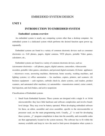
Evaluating simple I2C communications A data transfer is made up of the Mastersignalling a Start Condition, followed byone or two bytes containing address andcontrol information. The Start condition is defined by a highto low transition of SDA when SCL ishigh. A low to high transition of SDA while SCLis high defines a Stop condition One SCL clock pulse is generated foreach SDA data bit, and data may onlychange when the clock is low.6
Evaluating simple I2C communications The byte following the Start condition is made up of seven address bits, and onedata direction bit (Read/Write) All data transferred is in units of one byte, with no limit on the number of bytestransferred in one message. Each byte must be followed by a 1-bit acknowledge from the receiver, duringwhich time the transmitter relinquishes SDA control.7
I2C on the mbedThe mbed I2C library functions are shown in the table below:I2CAn I2C Master, used for communicating with I2C slave devicesFunctionsUsageI2CCreate an I2C Master interface, connected to the specified pinsfrequencySet the frequency of the I2C interfacereadRead from an I2C slavereadRead a single byte from the I2C buswriteWrite to an I2C slavewriteWrite single byte out on the I2CC busstartCreates a start condition on the I2C busstopCreates a stop condition on the I2C bus8
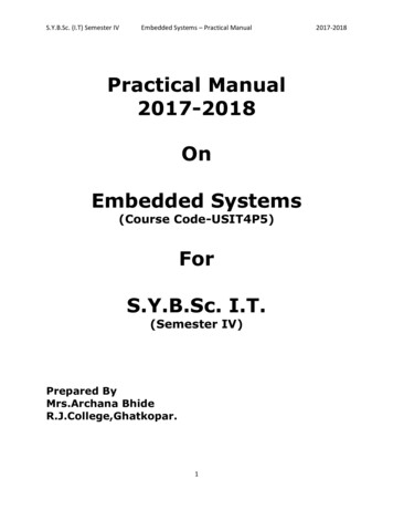
I2C on the mbed The I2C Interface can be used onmbed pins p9/p10 and p28/p27 Note also that the SDA and SCLdata signals each need to be‘pulled up’ to 3.3V, with aresistor value which can beoptimised for the exact circuitconfiguration; in this setup wechoose 2.2 kΩ resistor9
Evaluating the TMP102 I2C temperature sensor Configuration and data register details are given in the TMP102 data pdf To configure the temperature sensor we need to:– Use arrays of 8-bit values for the data variables, because the I2C bus can onlycommunicate data in one bytes.– Set the configuration register; we first need to send a data byte of 0x01 to specify thatthe Pointer Register is set to ‘Configuration Register’.– Send two bytes of data to perform the configuration. A simple configuration value toinitialise the TMP102 to normal mode operation is 0x60A0. To read the data register we need to:– To read the data register we need to set the pointer value to 0x00.– To print the data we need to convert the data from a 16-bit data reading to an actualtemperature value. The conversion required is to shift the data right by 4 bits (itsactually only 12-bit data held in two 8-bit registers) and to multiply by the 1-bitresolution which is 0.0625 degrees C per LSB.10
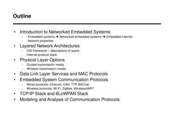
Interfacing the TMP102 with the mbed The TMP102 can be connected to the mbed as shown:SignalTMP102 MbedPinPinVcc (3.3V)140Gnd (0V)41SDA29SCL310Notes2.2kΩ pull-upto 3.3V2.2kΩ pull-upto 3.3V11
Working with the TMP102 I2Ctemperature sensor Exercise 1: Connect the temperature sensor to an I2C bus. Verifythat the correct data can be read by continuously display updates oftemperature to the screen.– Test that the temperature increases when you press your fingeragainst the sensor. You can even try placing the sensor on somethingwarm, for example a pocket hand warmer, in order to check that itreads temperature correctly.12
Working with the TMP102 I2Ctemperature sensorThe following program will configure the TMP102 sensor, read data, convert datato degrees Celsius and then display values to the screen every second:#include "mbed.h“I2C tempsensor(p9, p10); //sda, sc1Serial pc(USBTX, USBRX); //tx, rxconst int addr 0x90;char config t[3];char temp read[2];float temp;int main() {config t[0] 0x01;//set pointer reg to 'config register'config t[1] 0x60;// config data byte1config t[2] 0xA0;// config data byte2tempsensor.write(addr, config t, 3);config t[0] 0x00;//set pointer reg to 'data register'tempsensor.write(addr, config t, 1);//send to pointer 'read temp'while(1) {wait(1);tempsensor.read(addr, temp read, 2);//read the two-byte temp datatemp 0.0625 * (((temp read[0] 8) temp read[1]) 4); //convert datapc.printf("Temp %.2f degC\n\r", temp);}}13
Evaluating the SRF08 ultrasonic rangefinder Configuration and data register details are given in the SRF08 data 8-1086.pdf The following information summarises the configuration and data readprocedures for the SRF08:– The rangefinder I2C address is 0xE0.– The pointer value for the command register is 0x00.– A data value of 0x51 to the command register initialises the range finder to operate andreturn data in cm.– A pointer value of 0x02 prepares for 16-bit data (i.e. two bytes) to be read.14
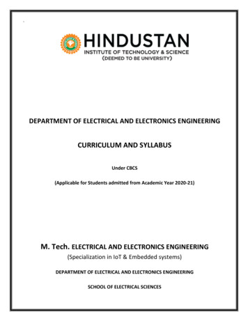
Interfacing the SRF08 with the mbed The SRF08 ultrasonic range finder is an I2C device whichmeasures distance and proximity of items The SRF08 can be connected to the mbed as shown:15
Working with the SRF08 ultrasonicrangefinder Exercise 2: Configure the SRF08 ultrasonic rangefinder to update distancedata to the screen. The following code will perform this operation:#include "mbed.h"I2C rangefinder(p9, p10); //sda, sc1Serial pc(USBTX, USBRX); //tx, rxconst int addr 0xE0;char config r[2];char range read[2];float range;int main() {while (1) {config r[0] 0x00;//set pointer reg to ‘cmd register'config r[1] 0x51;// config data byte1rangefinder.write(addr, config r, 2);wait(0.07);config r[0] 0x02;//set pointer reg to 'data register'rangefinder.write(addr, config r, 1);//send to pointer 'read range'rangefinder.read(addr, range read, 2);//read the two-byte range datarange ((range read[0] 8) range read[1]);pc.printf("Range %.2f cm\n\r", range); //print range on screenwait(0.05);}}16
Working with the SRF08 ultrasonicrangefinder Exercise 3:Evaluate the SRF08 datasheet to understand the different controlsetup and data conversion options.Now configure the SRF08 to accurately return data in inchesmeasured to a maximum range of 10 feet.Note:1 inch 25.4 mm1 foot 12 inches17
Interfacing multiple devices on an I2C bus Exercise 4: Connect both the temperature sensor and the range finder tothe same I2C bus and verify that the correct data can be read byaddressing commands appropriately. Update your screen readout tocontinuously display updates of temperature and detected range.18
Extended Exercises Exercise 5: Use an ultrasonic range finder to control the position ofa servo motor. When items are distant, the servo will take a 0degrees position, but as objects come within range of the SRF08,the servo will move towards a 180 degrees position. Exercise 6: Communicate between two mbeds on an I2C bus.Program the master mbed to count a value from 0 to 15 and tobroadcast this count value on the I2C bus. The slave mbed should beprogrammed to read the I2C data at regular intervals and set theonboard LEDs to display the binary count value.19
Summary Introducing I2CEvaluating simple I2C communicationsI2C on the mbedWorking with the TMP102 I2C temperature sensorWorking with the SRF08 ultrasonic rangefinderInterfacing multiple devices on a single I2C busExtended exercises20
Embedded Systems Design Course Applying the mbed microcontroller 1 These course notes are written by R.Toulson (Anglia Ruskin University) and T.Wilmshurst (University of Derby). (c) ARM 2012 These course notes accompany the textbook Fast and effective embedded