Transcription
International Journal of Civil and Structural Engineering Research ISSN 2348-7607 (Online)Vol. 3, Issue 2, pp: (1-10), Month: October 2015 - March 2016, Available at: www.researchpublish.comAnalysis and Design of Prestressed ConcreteBox Girder by Finite Element Method(3 Cells & 1 Cell)1Mayank Chourasia, 2Dr. Saleem Akhtar1PG Scholar, Department of Civil Engineering, UIT-RGPV, Bhopal2Professor, Department of Civil Engineering, UIT-RGPV, BhopalAbstract: The design of a highway bridge is critically dependent on standard norms of a particular region orcountry and criteria like loadings and support conditions. Naturally, the importance of highway bridges in amodern transportation system would imply a set of rigorous design specifications to ensure the safety, quality andoverall cost of the project. This paper discusses the parametric study of two different cross-sections of box-girderfor same loading conditions to find the most economical cross-section. The design standard of India, IRC wasfollowed in design of Box-girder superstructures subjected to IRC class AA loading. Optimized Cross-sections wasfound by comparing the different design parameters. As result of this exercise it was found that bending momentand stresses for self-weight and superimposed dead load were different for different cross-section. The crosssection with minimum value of bending moment requires less steel to counter the bending stresses. Lessreinforcement leads to the most economical cross-section for box girder. The result shows the multi cell box girdersare costlier as compare to the single cell box girder, when the loading and support condition were kept same forboth the cross-section. Analysis is carried out using the MIDAS Civil Software which is based on finite elementmethod of analysis.Keywords: Pre-stressed Concrete, Box-girder, IRC loading.1. INTRODUCTIONFor design of Highway and Railway Bridge superstructures there are many codes used around the world and most of thecountries have their own code depending on the natural conditions and the surrounding environmental factors, such as theseismic effects, heavy rainfall, heavy snowfall, mountainous terrain, different types of vehicle used in country etc. Indianbridge engineers refer IRC (Indian Road Congress) standard for the structural design. In this study two box-girder crosssections were designed with different cross section- i) Pre-stressed concrete box girder with three cells, ii) Pre-stressedconcrete box girder with single cell. The design parameters were kept same for both of the cross-sections. Moving load asper IRC-6: 2000 were considered for both the cross-section and standard moving load IRC Class AA was applied.Comparison was done between the results of both the box-girder cross-sections.Problem Statement: - Design a box girder for 2 lane national highway bridge, with following parameters: Support condition:- simply supported Span length:- 30 m Width of carriageway:- 7.5m Width of foot path:- 1.25m Total width of segment:- 10m Moving load :- IRC class AA loadingPage 1Research Publish Journals
International Journal of Civil and Structural Engineering Research ISSN 2348-7607 (Online)Vol. 3, Issue 2, pp: (1-10), Month: October 2015 - March 2016, Available at: www.researchpublish.com2. THREE CELLS PRE-STRESSED CONCRETE BOX GIRDERTo achieve our goal first we model a three cells pre-stressed concrete box girder cross-section. Following are the variousdetails of three cell box-girder cross-section.1. Material Properties And Allowable Stress:Concrete properties: Grade: M60Tendon Properties:Pre-stressing Strand: ϕ15.2 mm (0.6”strand)Yield Strength: fpy 1.56906 X 10⁶ kN/m2Ultimate Strength: fpu 1.86326 X 10⁶ kN/m2Cross Sectional area of each tendon 0.0037449 m2Modulus of Elasticity: Eps 2 X 10⁸ kN/m2Jacking Stress: fpj 0.7fpu 1330 N/mm2Curvature friction factor: µ 0.3 /radWobble friction factor: k 0.0066 /mAnchorage Slip: s 6 mm (At the Beginning and at the End)2. Cross Section Specification:3 Cells Concrete Box-Girder with two traffic lanesVertical side wallsTop slab thickness 300 mmBottom Slab thickness 300 mmExternal wall thickness 300 mmInternal Wall thickness 300 mmSpan 30mTotal width 10m Road (Including 1.25m of foot path both side)Width of Carriage way 7.5mWearing coat 80mmCross-sectional Area 7.65 m2Ixx 1.241 X 101 m4Iyy 4.405 m4Izz 5.553 X 101 m4Center: y 5 mCenter: z 1.0633 mThickness of web (As per IRC: 18 – 2000):The thickness of the web shall not be less than d/36 plus twice the clear cover to the reinforcement plus diameter of theduct hole where„d‟ is the overall depth of the box girder measured from the top of the deck slab to the bottom of the soffitor 200 mm plus the diameter of duct holes, whichever is greater.Thickness of the web in model 300 mm permissible value (hence safe)Page 2Research Publish Journals
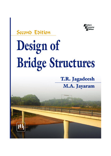
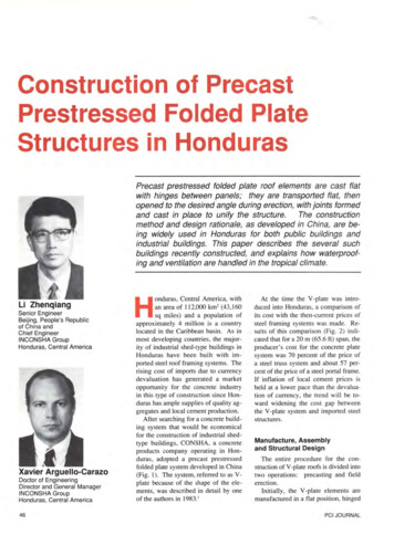
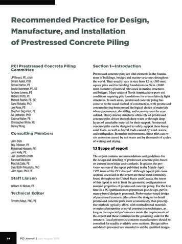
International Journal of Civil and Structural Engineering Research ISSN 2348-7607 (Online)Vol. 3, Issue 2, pp: (1-10), Month: October 2015 - March 2016, Available at: www.researchpublish.comThickness of Bottom Flange (As per IRC: 18 – 2000):The thickness of the bottom flange of box girder shall be not less than 1/20th of the clear web spacing at the junction withbottom flange or 200 mm whichever is more.Thickness of the bottom flange in model 300 mm permissible value (hence safe)Thickness of Top Flange (As per IRC: 18 – 2000):The minimum thickness of the deck slab including that at cantilever tips be 200 mm. For top and bottom flange havingpre-stressing cables, the thickness of such flange shall not be less than 150 mm plus diameter of duct hole.Thickness of the Top Flange in model 300 mm permissible value (hence safe)Fig.1 Cross-sectional details of 3 cells Concrete Box Girder (all dimension are in meter)Fig.2 Perspective view of 3 cells Concrete Box Girder3. Loading On Box GirderThe various type of loads, forces and stresses to be considered in the analysis and design of the various components of thebridge are given in IRC 6:2000 (Section II) But the common forces are considered to design the model are as follows:The model is designed by considering IRC Class AA loading (for complete detail refer IRC 6: 2000, Clause no 207.1,Page no. 10)4. Calculation of Ultimate Strength (As per IRC:18-2000):i) Failure by yield of steel (under-reinforced section)Mult 0.9dbAsFpii) Failure by crushing concreteMult 0.176 b db 2fckPage 3Research Publish Journals
International Journal of Civil and Structural Engineering Research ISSN 2348-7607 (Online)Vol. 3, Issue 2, pp: (1-10), Month: October 2015 - March 2016, Available at: www.researchpublish.comUltimate Moment of Resistance (Analysis Result): Positive MomentCheck for moment of resistance,Designed value of the applied internal bending moment M Ed 18375.546kN.m(From analysis of the model)Designed Moment of resistance, MRd 145662.395kN.m,Hence, Structure is safe. Negative MomentCheck for moment of resistance,Designed value of the applied internal bending moment M Ed 0.00kN.m(From analysis of the model)Designed Moment of resistance, MRd 164050.427kN.m,Hence, Structure is safe.Shear reinforcement (As per IRC 18: 2000 Clause 14.1.4):When V, the shear force due to ultimate load is less than Vc/2 then no shear reinforcement need to be provided. Minimumshear reinforcement shall be provided when V is greater than Vc/2 in the form of linksWhen shear force V, due to ultimate load exceeds Vc, the shear reinforcement provided shall be such thatYesVEdVRdNo shear reinforcement requiredNoShear reinforcementrequiredFig.3 Flow-chart for shear reinforcementDesigned value of the applied internal shear force VEd 319.454kNDesigned shear force,VRd (Iㆍbw / S)ㆍ ((fctd)2 αlㆍσcpㆍfctd ) (νmin k1ㆍσcp)ㆍbwㆍdp 5234.389kNVEd VRdPage 4Research Publish Journals
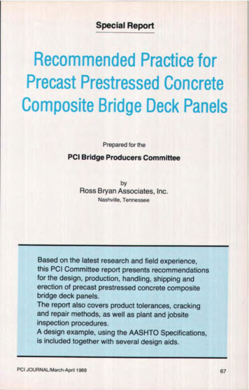
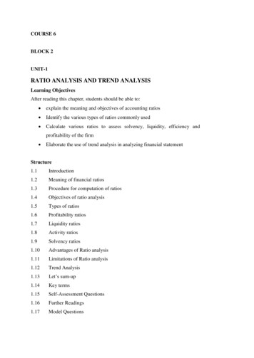
International Journal of Civil and Structural Engineering Research ISSN 2348-7607 (Online)Vol. 3, Issue 2, pp: (1-10), Month: October 2015 - March 2016, Available at: www.researchpublish.comFig.4 Beam Diagram 3 cells Concrete Box GirderMaximum Bending moment at element 15 i.e. Middle of the section 8465.5 kN.mMaximum Deflection at element 15 7.862 mmTotal consumption of concrete for 3 cell box girder 229.5 m3Steel Consumption for 3 cell box girder 24.922 MTTotal Consumption of Strand for 3 cell girder 360.496 m3.SINGLE CELL PRE-STRESSED CONCRETE BOX GIRDERNow we model a single cell pre-stressed concrete box girder cross-section. Following are the various details of single cellbox-girder cross-section.1. Material Properties And Allowable Stress:Concrete properties: Grade: M60Tendon Properties:Pre-stressing Strand: ϕ15.2 mm (0.6”strand)Yield Strength: fpy 1.56906 X 10⁶ kN/m2Ultimate Strength: fpu 1.86326 X 10⁶ kN/m2Cross Sectional area of each tendon 0.0037449 m2Modulus of Elasticity: Eps 2 X 10⁸ kN/m2Jacking Stress: fpj 0.7fpu 1330 N/mm2Curvature friction factor: µ 0.3 /radWobble friction factor: k 0.0066 /mAnchorage Slip: s 6 mm (At the Beginning and at the End)2. Cross Section Specification:1 Cell Concrete Box-Girder with two traffic lanesTrapezoidal ShapeTop slab thickness (Tapered) at the center 300 mm & at corner 200 mmBottom Slab thickness 200 mmExternal wall thickness 300 mmSpan 30mPage 5Research Publish Journals
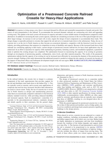
International Journal of Civil and Structural Engineering Research ISSN 2348-7607 (Online)Vol. 3, Issue 2, pp: (1-10), Month: October 2015 - March 2016, Available at: www.researchpublish.comTotal width 10m Road (Including 1.25m of foot path both side)Width of Carriage way 7.5mWearing coat 80mmCross-sectional Area 4.620 m2Ixx 5.199 X 101 m4Iyy 2.353 m4Izz 2.652 X 101 m4Center: y 5 mCenter: z 1.355 mThickness of web (As per IRC: 18 – 2000):The thickness of the web shall not be less than d/36 plus twice the clear cover to the reinforcement plus diameter of theduct hole where„d‟ is the overall depth of the box girder measured from the top of the deck slab to the bottom of the soffitor 200 mm plus the diameter of duct holes, whichever is greater.Thickness of the web in model 300 mm permissible value (hence safe)Thickness of Bottom Flange (As per IRC: 18 – 2000):The thickness of the bottom flange of box girder shall be not less than 1/20th of the clear web spacing at the junction withbottom flange or 200 mm whichever is more.Thickness of the bottom flange in model 300 mm permissible value (hence safe)Thickness of Top Flange (As per IRC: 18 – 2000):The minimum thickness of the deck slab including that at cantilever tips be 200 mm. For top and bottom flange havingpre-stressing cables, the thickness of such flange shall not be less than 150 mm plus diameter of duct hole.Thickness of the Top Flange in model 300 mm permissible value (hence safe)Fig.5 Cross-sectional details of Single cells Concrete Box Girder (all dimensions are in meter)Fig.6 Perspective view of Single cells Concrete Box GirderPage 6Research Publish Journals
International Journal of Civil and Structural Engineering Research ISSN 2348-7607 (Online)Vol. 3, Issue 2, pp: (1-10), Month: October 2015 - March 2016, Available at: www.researchpublish.com3.Loading On Box Girder:The various type of loads, forces and stresses to be considered in the analysis and design of the various components of thebridge are given in IRC 6:2000 (Section II) But the common forces are considered to design the model are as follows:The model is designed by considering IRC Class AA loading (for complete detail refer IRC 6: 2000, Clause no 207.1,Page no. 10)Calculation of Ultimate Strength (As per IRC: 18-2000, Clause no. 13):i) Failure by yield of steel (under reinforced section)Mult 0.9dbAsFpii) Failure by crushing concreteMult 0.176 b db 2fck4.Ultimate Moment of Resistance (Analysis Result ): Positive MomentCheck for moment of resistance,Designed value of the applied internal bending moment MEd 14893.728kN.m(From analysis of the model)Designed Moment of resistance, MRd 85812.438kN.m,Hence, Structure is safe. Negative MomentCheck for moment of resistance,Designed value of the applied internal bending moment M Ed 0.00kN.m(From analysis of the model)Designed Moment of resistance, MRd 103656.221kN.m,Hence, Structure is safe.Shear reinforcement (As per IRC 18: 2000 Clause 14.1.4)When (V VEd), the shear force due to ultimate load is less than (Vc/2 VRd) then no shear reinforcement need to beprovided. Minimum shear reinforcement shall be provided when (V VEd) is greater than (Vc/2 VRd) in the form of linksWhen shear force (V VEd), due to ultimate load exceeds Vc, the shear reinforcement provided shall be such thatYesVEdVRdNo shear reinforcement requiredNoShear reinforcement requiredFig.7 Flow-chart for shear reinforcementPage 7Research Publish Journals
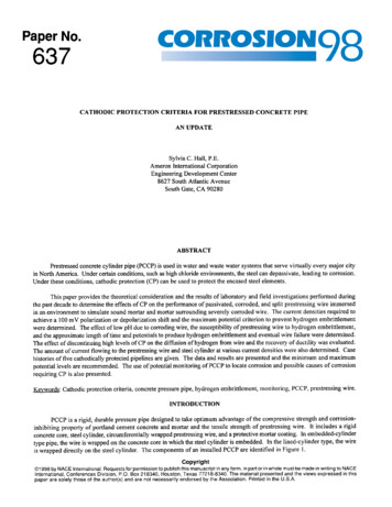
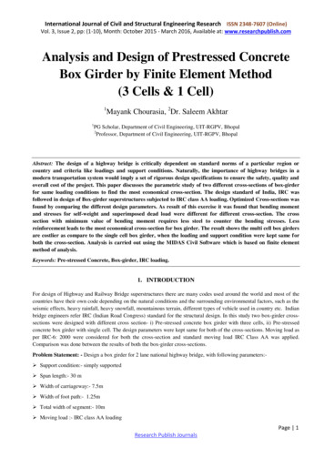
International Journal of Civil and Structural Engineering Research ISSN 2348-7607 (Online)Vol. 3, Issue 2, pp: (1-10), Month: October 2015 - March 2016, Available at: www.researchpublish.comDesigned value of the applied internal shear force VEd 600.456kNDesigned shear force,VRd (Iㆍbw / S)ㆍ ((fctd)2 αlㆍσcpㆍfctd ) (νmin k1ㆍσcp)ㆍbwㆍdp 4668.975kNVEd VRdFig.8 Beam Diagram Single cells Concrete Box GirderMaximum Bending moment at element 15 i.e. Middle of the section 6276.96 kN.mMaximum Deflection at element 15 7.189 mmTotal consumption of concrete for Single cell box girder 138.6 m3Steel Consumption for Single cell box girder 18.167 MTTotal Consumption of Strand for Single cell girder 180.285 m4.RESULTS & DISCUSSIONTable: 1 Comparison between the Results of 3 cells & single cell Box girderSr. No.12345ParametersBending MomentMaximum DeflectionConcrete ConsumptionSteel ConsumptionStrand Consumption3 cells8465.5kN.m7.862 mm229.5 m324.992 MT360.496 m1 Cell6276.96kN.m7.189 mm138.6 m318.167 MT180.285 mBending Moment (kN.m)9000800070006000500040003000200010000One CellType of Box-GirderThree CellsFig.9 Graph showing comparison between bending moment and types of Box GirderPage 8Research Publish Journals
International Journal of Civil and Structural Engineering Research ISSN 2348-7607 (Online)Vol. 3, Issue 2, pp: (1-10), Month: October 2015 - March 2016, Available at: www.researchpublish.comConcrete Consumption (m3)250200150100500One CellType of Box-GirderThree CellsFig.10 Graph Showing Comparison between Concrete Consumption and Types of Box-GirderSteel Consumption (MT)302520151050One CellType of Box-GirderThree CellsFig.11 Graph Showing Comparison between Steel Consumption and Types of Box-GirderPre-stressing Steel Consumption(Running Meter)400350300250200150100500One CellType of Box-GirderThree CellsFig.12 Graph Showing Comparison between Pre-stressing Steel Consumption and Types of Box-GirderBy comparison of the results for consumption of concrete, steel and pre-stressing strands are less for single cell boxgirder. Shown in the table-1 and graph is drawn with reference to the table.5.CONCLUSIONA comparative study between three cell and single cell pre-stressed concrete box girder Cross-sections has been done.This study shows that the single cell pre-stressed concrete box girder is most suitable and economical cross-section for 2lane Indian national highway bridges.Page 9Research Publish Journals
International Journal of Civil and Structural Engineering Research ISSN 2348-7607 (Online)Vol. 3, Issue 2, pp: (1-10), Month: October 2015 - March 2016, Available at: www.researchpublish.comREFERENCES[1]IRC: 6- 2000 “Standard specifications and code of practice for road bridges” Indian road congress.[2]IRC: 18 – 2000 “Design criteria for pre-stressed concrete road bridges (post – tensioned concrete)” Indian roadscongress[3]IS: 1343 – 1980 “Code of practice for pre-stressed concrete” Indian standards.[4]IRC: 21 –2000 “Standard specification and code of practice for road bridges (Plain and Reinforced)” Indian roadcongress.[5]Priyanka Bhivgade, “Analysis and design of pre-stressed concrete box Girder Bridge” Civil engineering portal.[6]Muhammad Abid, “Optimization of Box Type Girder of Overhead Crane for Capacities with Fixed Span Different”9th International Conference on Fracture & Strength of Solids, June 9-13, 2013, Jeju, Korea.[7]Ahemad S.Debaiky, “Analysis of time dependent Effect on segmental Pre-stressed concrete curved Box GirderBridges”[8]Martine Alenius, “Finite element Modelling of composite Bridge Stability” Royal Institute of TechnologyStockholm, 2003.[9]Mohanned I. Mohammed Hussein, “Finite Element Analysis of Post- Tensioned concrete Box Girder” University ofBagdad, 2007[10] Sandy Shuk-Yan Poon, “Optimization of Span to Depth Ratios in High Strength Concrete Girder Bridges”,Department of Civil Engineering, University of Toronto 2009.[11] Feraz Temimi, “Eathquake analysis of curved cellular Bridges” Civil engineering department, University of Bagdad,2013[12] Laxmi Priya Gouda, “Study on Parametric Behaviour of Single Cell Box Girder under Different Radius ofCurvature” Department of Civil Engineering, NIT-Rourkela, 2013.[13] Patil Yashavant S, “Comparative Analysis and Design of Box Girder Bridge with two different codes” Dept. ofStructural Engineering, Jawaharlal Nehru Engineering College, Aurangabad, Maharashtra. India, 2013[14] Kuppumanikanand A, “Study on Major Elements of an Elevated Metro Bridge”, Department of Civil Engineering,NIT-Rourkela, 2013Page 10Research Publish Journals
Fig.1 Cross-sectional details of 3 cells Concrete Box Girder (all dimension are in meter) Fig.2 Perspective view of 3 cells Concrete Box Girder 3. Loading On Box Girder The various type of loads, forces and stresses to be co