Transcription
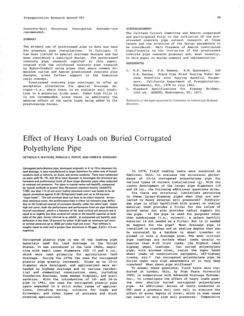
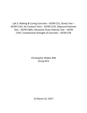
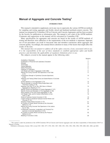
Optimization of a Prestressed Concrete RailroadCrosstie for Heavy-Haul ApplicationsDevin K. Harris, A.M.ASCE1; Russell H. Lutch2; Theresa M. Ahlborn, M.ASCE3; and Pelle Duong4Abstract: In response to rising energy costs, there is increased demand for efficient and sustainable transportation of people and goods. Onesource of such transportation is the railroad. To accommodate the increased demand, railroads are constructing new track and upgradingexisting track. This update to the track system will increase its capacity and make it a more reliable means of transportation compared to otheralternatives. In addition to increasing the track system capacity, railroads are considering an increase in the size of the typical freight rail car toallow larger tonnage. An increase in rail car loads will, in turn, require the design of track components to accommodate these loads. Thisdesign change is especially pertinent to crossties that support the rail and serve to transmit loads down to the substructure. Today, the use ofconcrete ties is on the rise in North America as they become an economical alternative, competitive with the historical wood ties used inindustry, providing performance that surpasses its competition in terms of durability and capacity. Because of the increased loads heavy-haulrailroads are considering applying to their tracks, current designs of prestressed concrete railroad ties for heavy-haul applications may beundersized. In an effort to maximize tie capacity while maintaining tie geometry, fastening systems, and installation equipment, a parametricstudy to optimize the existing designs was completed. The optimization focused on maximizing the capacity of an existing tie geometrythrough an investigation of prestressing quantity, configuration, stress levels, and other material properties. The results of the parametricoptimization indicate that the capacity of an existing tie can be increased most efficiently by increasing the diameter of the prestressing andconcrete strength. Findings of the study demonstrate that additional research is needed to evaluate the true capacity of concrete ties because ofthe impacts of deep beam effects and inadequate development length in the rail seat region. DOI: 10.1061/(ASCE)TE.1943-5436.0000256. 2011 American Society of Civil Engineers.CE Database subject headings: Prestressed concrete; Railroad tracks; Optimization; Energy efficiency.Author keywords: Concrete tie; Sleepers; Prestressed concrete; Railroad; Optimization.IntroductionIn the railroad industry, the crosstie (tie) or sleeper is a primarycomponent of the track superstructure that provides support forthe rail and distributes train loads down to the ballast (Fig. 1). Tiesare typically wood or concrete, and in recent years applications ofcomposite and steel ties have increased, but these latter alternativesare used to a lesser extent. Today, the use of concrete ties is on therise in North America as designs and manufacturing processesmake them an economically competitive alternative to the historicalindustry standard wood ties, while providing enhanced durabilityand increased capacity. Each tie manufacturer—somewhat of aspecialty in the precast/prestressed industry—maintains designsand details specific to their customers, but the general shape,1Assistant Professor, Dept. of Civil and Environmental Engineering,Michigan Technological Univ., Houghton, MI 49931 (correspondingauthor). E-mail: dharris@mtu.edu2Project Engineer, Kiewit Engineering Co., Omaha, NE 68131. E-mail:russell.lutch@kiewit.com3Associate Professor, Dept. of Civil and Environmental Engineering,Michigan Technological Univ., Houghton, MI 49931. E-mail: tess@mtu.edu4Engineering Manager, L. B. Foster CXT Inc., Spokane, WA 99216.E-mail: pduong@cxtinc.comNote. This manuscript was submitted on September 19, 2010; approvedon December 28, 2010; published online on December 30, 2010. Discussion period open until April 1, 2012; separate discussions must be submitted for individual papers. This paper is part of the Journal ofTransportation Engineering, Vol. 137, No. 11, November 1, 2011. ASCE, ISSN 0733-947X/2011/11-815–822/ 25.00.dimensions, and regions common to North American concrete tiesare illustrated in Fig. 2.The design of prestressed concrete ties is somewhat similarto other prestressed members in the United States but followsAmerican Railway Engineering and Maintenance-of-Way Association (AREMA) (2009) guidelines and customer specificationsrather than building and highway codes such as ACI 318 andAASHTO-LRFD. However, AREMA is not categorized as a designcode and often refers to ACI 318 [American Concrete Institute(ACI) 2008] or other material specifications for design methods.Additionally, recommendations within AREMA are often superseded by customer specifications that are typically more stringentthan those of AREMA, resulting in a tie designed above the requirements of AREMA.While the general approach for prestressed concrete ties is similar to that of other prestressed members such as bridge girders, thein-service conditions and design load scenarios present a significantchallenge in the design process.In-Service ConditionsWhen placed in service, concrete ties are subjected to a variety ofloading conditions, including environmental effects, train loads,and ballast support loads, all of which vary over time. Ballast loadsare highly dependent on maintenance and time from installationbecause the condition of the ballast degrades and support shiftsover time (Fig. 3). The fraction of load transmitted to each tie fromthe rail is assumed to be proportional to tie spacing (AREMA2009), analogous to lateral load distribution in highway bridges,and also includes the effects of impact from moving trains. Theresult of these effects yields two critical regions along the tie,JOURNAL OF TRANSPORTATION ENGINEERING ASCE / NOVEMBER 2011 / 815Downloaded 19 Jan 2012 to 192.17.126.205. Redistribution subject to ASCE license or copyright. Visit http://www.ascelibrary.org
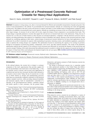
in the railroad industry is very specialized. However, there still exists the need to increase the capacity of tie designs while addressingthese challenges. The objective of the work presented is to increasethe flexural design capacity of an existing heavy-haul prestressedconcrete tie while maintaining the existing geometry of the crosssection.Objective and Scope of InvestigationFig. 1. Distribution of load from single axle along trackThe work presented herein is an analytical investigation of theoptimization scenarios for the 505S heavy-haul concrete tie manufactured by L. B. Foster CXT. This tie is typical of the proven design used by Union Pacific Railroad for heavy-haul operations andeven exceeds capacity requirements. Alternatives are evaluated forincreasing the flexural capacity of the 505S tie while maintainingthe cross-sectional geometry, in anticipation of the transition ofthe railroad industry to larger train loads. Variations in concretestrength, strand/wire configuration and type were parameters considered in the optimization process. The current 505S tie designwas used as a baseline for comparison of the optimized designs.Design ValidationFig. 2. Generic concrete tie shape and dimensionsthe rail seat and center regions (Fig. 2), for which the tie must bedesigned and tested per AREMA.Design ScenariosAREMA provisions provide guidance on specific aspects of prestressed concrete design as they relate to railroad applicationsbut refers to ACI 318 (ACI 2008) for the methodology related toprestressed concrete member behavior and design. The key difference included in AREMA is the definition of flexural strength, defined as the capacity to resist flexural cracking of the member. Thisdefinition is not explicitly defined but inferred based on the qualification testing program required of each design that deems a tieacceptable if no cracking is observed under factored design loads.This testing program includes both positive and negative bendingtests at the rail seat and center regions of the tie (Figs. 4–7). Thisdiffers from ACI 318 design definitions, which include bothserviceability requirements on stresses and ultimate strength criteria based on member capacity. Additional requirements includedwithin AREMA relate to performance of the tie under cyclic flexural loads and bond development based on a magnified design loadcriterion.Research SignificanceWith the recent reemergence of the railroads as a major stakeholderin the transportation of goods within the United States comes reflection on operations within the industry. One key consideration isthe transition to larger capacity and heavier railroad cars (from1,272 to 1,401 kN) that are capable of carrying more goods. Withthese potential changes comes the need to upgrade existing infrastructure to accommodate the increased loads resulting from largercars. For concrete tie manufacturers, this presents a major challengebecause the production of concrete ties is a manufacturing processwith significant capital costs for forms and facilities. Other considerations include installation challenges because ties are alreadyheavy and increasing their size would result in a decrease in efficiency, especially considering that installation equipment usedTo date, limited published results are available for prestressedconcrete ties used in North America, which have historically onlybeen available “in-house” from manufacturers or Class I railroadoperators. To validate the optimization approach, design information and experimental results provided by CXT were used for comparison of the 505S analysis. Upon validation of the analyticalprocedure, the optimization was initiated considering the variablespreviously noted.Design AssumptionsTwo critical sections were considered in the analysis of the 505S tiecapacity—the rail seat and center sections—under both positiveand negative bending scenarios. These scenarios replicate the conditions used during tie tests based on AREMA acceptance criteria.Both the service limit state and the nominal flexural capacity wereconsidered, even though AREMA places an upper limit on capacitysuch that cracking to the first layer of prestressing does not occur.This latter definition is somewhat in disagreement with the traditional definition of ultimate flexural capacity and is more in linewith a service limit state. Within this work, the different limit stateswill be described as (1) service capacity for the ACI serviceabilitylimits of transfer and service loads (ACI 2008), (2) AREMA capacity defining the first cracking capacity (AREMA 2009), and (3) ultimate capacity describing the nominal strength of the member.Much of the information provided by CXT was from historicalpractice and experimental results and, as such, resulted in a degreeof uncertainty in the analyses. In these cases, existing design provisions such as ACI 318 (ACI 2008) and the Prestressed/PrecastConcrete Institute (PCI) Design handbook (PCI 2004) were usedto provide guidance. ACI 318 was used to determine material characteristics such as modulus of elasticity and allowable concreteand steel service stress limits (Table 1). ACI 440-02 (ACI Committee 440 2004) was used for the allowable stress limits of fiberreinforced polymer (FRP) (Table 1). Similarly, the PCI Designhandbook (PCI 2004) was used for prestressing steel stress-strainrelationships. Neither provision specifies the preferred method fordetermining losses, but both provide references for alternatives, including the time-step method proposed by Zia et al. (1979) that wasused in the tie analyses. The loss information provided by CXT waslimited to 1,000 h ( 40 days), but the analyses also considered an816 / JOURNAL OF TRANSPORTATION ENGINEERING ASCE / NOVEMBER 2011Downloaded 19 Jan 2012 to 192.17.126.205. Redistribution subject to ASCE license or copyright. Visit http://www.ascelibrary.org
Fig. 3. Ballast support distribution configurations: (a) support following installation owing to tamping only around rail; (b) train traffic consolidatingballast; (c) extensive train traffic; (d) degraded ballast “center-bound” conditioninterval of 5 years to account for the long-term effects of concretecreep and shrinkage and steel relaxation, factors which wouldlikely affect in-service ties. Details of the time-step method arenot presented in this paper but include contributions from elasticshortening, steel relaxation, anchorage set, creep, and shrinkage.Design Validation of 505SThe 505S tie was evaluated for two of the conditions previouslydescribed: (1) service limit state, and (2) ultimate capacity at boththe rail seat and center regions under both positive and negativebending conditions. The AREMA-defined limit state was not included because it was similar to the service limit state and wouldnot be expected to significantly differ owing to the limited tensilecapacity of concrete and the proximity of the prestressing steel tothe tension face. The ultimate capacity was selected to assess theadditional reserve capacity of prestressed concrete railroad ties,which is typically neglected in practice owing to the AREMAdefined service limit state.JOURNAL OF TRANSPORTATION ENGINEERING ASCE / NOVEMBER 2011 / 817Downloaded 19 Jan 2012 to 192.17.126.205. Redistribution subject to ASCE license or copyright. Visit http://www.ascelibrary.org
Some sources of discrepancy between the experimental and design capacities include differences in compressive strength, losses,failure criteria (service versus AREMA), allowable tensile stress,which is not included within AREMA, and deep beam behavior,which likely exists in the rail seat region (Lutch 2009). A key observation is the additional reserve capacity present beyond thecrack-limiting design criteria. This reserve capacity illustrates thatthe 505S ties are capable of supporting significantly higher loadsthat might result from larger trains but would still require a designchange to satisfy the AREMA limiting crack criterion.OptimizationFig. 4. Positive rail seat moment test configuration as outlined inAREMA 4.9.1, “Design test of monoblock ties” (data from AREMA2009)Fig. 5. Negative rail seat moment test configuration as outlined inAREMA 4.9.1, “Design test of monoblock ties” (data from AREMA2009)The tie manufacturer typically estimates losses at 40 days subsequent to casting; however, with an estimated service-life of 25 years for concrete ties, a 5-year loss estimate was also considered toaccount for long-term creep and shrinkage effects. Additionally, themanufacturer typically designs for a 48 MPa compressive strength,but typical strength gain curves (Fig. 8) illustrate that significantlyhigher compressive strengths are achieved prior to service. Bothvariations in compressive strength and prestress losses were considered in the analyses. A summary of the design capacities andexperimental results provided by CXT are presented in Table 2.To address the potential increase in railroad car loads, an optimization of the CXT 505S design was initiated. The goal of the optimization was to increase member capacity while maintaininggeometry, which is crucial from both a manufacturing perspectivewhere formwork and associated equipment are standardized andalso from a railroad track system perspective where installationand maintenance equipment is highly specialized. To optimizethe tie capacity variations in prestressing type, size, and configuration were evaluated along with the effects of different concretecompressive strengths that could be achieved in a precast environment. A summary of the parameters evaluated is presented inTable 3, resulting in 56 optimization analyses when consideringall loading scenarios. The objective function of the optimizationwas to determine the maximum service flexural capacity of thetie grouping. An additional resultant of this investigation wasthe ultimate capacity of the tie design from a strain compatibilityanalysis, which has some pertinence if the AREMA cracking criteria were modified in the future.The optimization was performed by selecting a set of parameters[e.g., W (PT)–0.21 (PD)–15 (CS)] and configuring the prestressingwithin the member to yield the largest service flexural capacity.Limitations on the optimization included the tie geometry limits,ACI 318 (ACI 2008) cover and spacing requirements for consistency, and prestressing strand stagger requirements to mitigate between strand cracking observed in the aligned pattern designs of thepast. The limitations were accounted for by establishing boundarytolerances and manually adjusting prestressing configurations toachieve the maximum eccentricity for the strand pattern (Fig. 9).Other limitations included the available space within the tie crosssection and limiting stresses in both the concrete and prestressingstrands. The resulting optimizations yielded designs with the largest capacity without cracking, with each of the parameters considered having varying effects on the tie capacity.Effects of Concrete Compressive StrengthIncreasing the compressive strength of the concrete affects twocomponents of the design procedure in particular. First, increasingFig. 6. Positive center moment test configuration as outlined in AREMA 4.9.1, “Design test of monoblock ties” (data from AREMA 2009)818 / JOURNAL OF TRANSPORTATION ENGINEERING ASCE / NOVEMBER 2011Downloaded 19 Jan 2012 to 192.17.126.205. Redistribution subject to ASCE license or copyright. Visit http://www.ascelibrary.org
Fig. 7. Negative center moment test configuration as outlined in AREMA 4.9.1, “Design test of monoblock ties” (data from AREMA 2009)Table 1. Allowable Service Stresses from ACI 318-08 and ACI 440.4R-04ACI Limit (ACICommittee 440 2004;ACI 2008)ConcreteReinforcementConcrete stress in compressionat transfer (σci )Concrete stress in tension attransfer (σti )Concrete stress in compression atservice owing to prestress andsustained loads (σcs1 )Concrete stress in compression atservice owing to prestress andtotal loads (σcs2 )Concrete stress in tension atservice (σts )Steel jacking stress (f pj )Steel stress after transfer (f pi )FRP jacking stress (f pj )FRP stress after transfer (f pi )0:60f 0ci ðMPaÞ0:25pffiffiffiffiffif 0ci ðMPaÞ0:45f 0c ðMPaÞ0:60f 0c ðMPaÞ0:62pffiffiffiffif 0c ðMPaÞ0:94f py but 0:80f pu ðMPaÞ0:82f py but 0:74f pu ðMPaÞ0:65f pu ðMPaÞ0:60f pu ðMPaÞFig. 8. CXT concrete strength gain over timethe compressive strength increases the allowable concrete stressesas specified by ACI 318-08, both at transfer and service limit states(Figs. 10 and 11). Increased allowable stresses at transfer permitincreases in both applied prestressing force and eccentricity, resulting in a higher flexural capacity.Similarly, increased allowable stresses at service allows the application of larger live loads prior to meeting the compression andtension limits that define failure. The second effect of higher concrete strengths is decreased prestress losses. The prestress losses ofcreep, shrinkage, and elastic shortening all have components thatare a function of the concrete design strength. Increasing the designstrength has the inverse effect of decreasing the total prestresslosses over time.Effects of Prestressing Variations (Type, Size, andConfiguration)Variations in prestressing offers multiple means of increasing the tiecapacity, such as higher strength materials, increased diameter oftendons, and the ability to optimize prestressing placement andeccentricity with respect to the constant concrete cross section. Forthe three different prestressing types selected for evaluation, drawnwire, 7-wire strand, and carbon fiber-reinforced polymer (FRP),each have their own advantages and disadvantages; however, allthree are capable of enhancing the flexural capacity of the tie.A relationship that became apparent during the optimizationstudy was the connection between concrete design strength and thelevel of prestressing within the section. As concrete design strengthincreased, a larger prestressing force could be applied. With theprestressing tendons in the tie already tensioned to their permissiblestress limits, the only means of increasing the prestressing forcewas to add more tendons to the section or increase the strand area(size). However, the number of tendons successfully placed withinthe cross section was limited by the detailing requirements of coverand spacing for the fixed cross section. These detailing limitations,in conjunction with the allowable concrete stresses (ACI Committee 440 2004; ACI 2008), dictated the prestressing quantity andconfiguration, as shown in Figs. 12 and 13. Each plateau illustratesthe transition from allowable stress-governed design to detailinggoverned design, which was typically associated with the smallerand lower capacity prestressing materials.Increasing the eccentricity of the prestressing strands in eitherdirection of the horizontal neutral axis, while maintaining the samelevel of prestressing, reorganizes the stress distribution on the concrete section, which may cause an increase in capacity in one condition and a decrease in another (Figs. 14 and 15). This effect ismore apparent at the rail seat section than the center section becausethe center section has smaller eccentricities resulting from a smallercross-sectional area (Fig. 2). Similar to the area of prestressing andconcrete strength relationship, allowable eccentricity generally increases as concrete strength increases. This increase is a result ofthe increase in allowable concrete stresses associated with highercompressive strength concrete. An exception to this observationoccurs with the FRP cases, which experience a decrease in allowable eccentricity with respect to concrete strengths greater than65 MPa. This variance results from the limitation on the jackingJOURNAL OF TRANSPORTATION ENGINEERING ASCE / NOVEMBER 2011 / 819Downloaded 19 Jan 2012 to 192.17.126.205. Redistribution subject to ASCE license or copyright. Visit http://www.ascelibrary.org
Table 2. Design and Experimental Flexural Capacities at Railseat (RS) and Center (C) of CXT 505SService (kN-m)Reserve strengthaUltimate (kN-m)CaseLosses atf 0c (MPa)f 0ci (MPa)þRS RSþC CþRS RSþC CþRS RSþC C123440 days5 years40 days5 /a106%103%97%112%n/aActualaReserve strength (%) ½ðUltimate ServiceÞ ðServiceÞ 100.Table 3. Summary of Optimization Parameters and NomenclaturePrestressing type (PT)DescriptionaDrawn wire7-wire strandbFRPcaPrestressing diameter (PD)Concrete strength signationW (PT)S (PT)FRP (PT)5.3 mm (0.21 in.)6.4 mm (0.25 in.)7.9 mm (0.3125 in.)9.5 mm (0.375 in.)0.21 (PD)0.25 (PD)0.3125 (PD)0.375 (PD)48.2 MPa (7,000 psi)65.5 MPa (9,500 psi)82.7 MPa (12,000 psi)103.4 MPa (15,000 psi)7 (CS)95 (CS)12 (CS)15 (CS)5.3-mm-diameter only.6.4-mm-, 7.9-mm-, and 9.5-mm-diameter only.6.4-mm- and 7.9-mm-diameter only.bcFig. 10. Allowable concrete compressive stresses at transfer andservice based on design concrete strengthsFig. 9. Optimization boundary templatestress that can be applied to the FRP as a result of the limited allowable concrete strength; however, as concrete strength increasesbeyond 65 MPa, FRP tendons can be pretensioned to a higherinitial stress and the eccentricity reduced.Section CapacityThe impacts of concrete compressive strength and prestressing typeand size allow for improvement in the tie capacity, as shown for therail seat (Fig. 16) and center (Fig. 17) regions of the tie. Similarresults were found for the ultimate strength of the tie designs(Figs. 18 and 19), with significant reserve capacity remainingbeyond the service limit state. Selecting which optimized designis the best and offers the greatest gain in capacity is difficult because no clear plateau or limit in capacity appears to exist forthe material parameter values considered. However, for the sameconcrete strength, larger diameter steel prestressing tendons haveFig. 11. Allowable concrete tensile stresses at transfer and servicebased on design concrete strengths820 / JOURNAL OF TRANSPORTATION ENGINEERING ASCE / NOVEMBER 2011Downloaded 19 Jan 2012 to 192.17.126.205. Redistribution subject to ASCE license or copyright. Visit http://www.ascelibrary.org
Fig. 12. Area of prestressing for positive rail seat momentFig. 15. Eccentricity at center section for negative center momentFig. 16. Positive rail seat moment capacity (service)Fig. 13. Area of prestressing for negative center momentFig. 14. Eccentricity at rail seat section for positive rail seatFig. 17. Negative center moment capacity (service)JOURNAL OF TRANSPORTATION ENGINEERING ASCE / NOVEMBER 2011 / 821Downloaded 19 Jan 2012 to 192.17.126.205. Redistribution subject to ASCE license or copyright. Visit http://www.ascelibrary.org
Fig. 18. Positive rail seat moment capacity (ultimate)Fig. 19. Negative center moment capacity (ultimate)larger strength gains than smaller diameter tendons. This becomesparticularly evident when detailing becomes the limiting factor indesign, rather than allowable stresses at transfer at higher concretestrengths. Based on this observation, the prestressing case S (PT)–0.375 (PD) appears to provide the largest gains for steel prestressing, whereas FRP prestressing appears to be unaffected by changesin diameter. This is a result of the higher strength associated withFRP strands that allows concrete stresses at transfer to remain thegoverning factor in design.ConclusionsAs the availability of suitable timbers for railroad ties decreases, theuse of prestressed concrete ties remains the most promising solution. This engineered product has the potential to provide longerservice-life, increased durability, better ride quality, and potentiallylower life-cycle costs than their timber counterpart. However,despite their suitability for the harsh railroad environment, a fitfor purpose-engineered design is still necessary, especially withthe progression to heavier railroad cars. As a result of this progression to heavier cars, there exists the need for a corresponding increase in prestressed concrete tie capacity to meet this demand.Presented was an optimization of a prestressed concrete tie manufactured by L. B. Foster CXT for heavy-haul operations. The objective of the optimization was to evaluate methods for increasingtie capacity while maintaining existing geometry. Parametersconsidered in this optimization included variations in concretecompressive strength, along with variations in prestressing type,size, and configuration within the cross section.From the flexural capacity optimization investigation, thefollowing conclusions can be drawn with respect to the impactsof the parameters on the AREMA-defined flexural capacity ofprestressed concrete railroad ties: Tie capacity increases as concrete design strength increases; forlower levels of concrete strength, capacity is governed by theallowable concrete stresses; As concrete strength increases, the governing limits on tiecapacity transition from concrete stress to the quantity ofprestressing that can be placed on the tie, while maintainingadequate spacing and cover; Smaller diameter prestressing tendons reach the governing limitof detailing before the larger tendon diameters, owing to thelarger number of tendons required to achieve the same prestressing force; Based on the optimization study presented, the following prestressing scenarios yield the greatest flexural capacity, in orderfrom highest to lowest: FRP (PT)–0.25 (PD); FRP (PT)–0.375(PD); S (PT)–0.375 (PD); S (PT)–0.3125 (PD); S (PT)–0.25(PD); W (PT)–0.21 (PD).While the recommendations presented in this work reflect methods for increasing capacity, associated cost, economy of modifications to the manufacturing process, and long-term performance areexpected to control the selected solution. Other factors that warrantconsideration include durability and fatigue resistance beyondthe AREMA-defined limit state which has been exceeded in someenvironments. Furthermore, this study did not consider deep beameffects or development length in the rail seat region, which warrantsfurther investigation.ReferencesAmerican Concrete Institute (ACI). (2008). “Building code requirementsfor structural concrete and commentary.” ACI 318-08, ACI 318R-08,Farmington Hills, MI.American Concrete Institute (ACI) Committee 440. (2004). 440.4R-04:Prestressing concrete structures with FRP tendons, Farmington Hills,MI.American Railway Engineering and Maintenance-of-Way Association(AREMA). (2009). Manual for railway engineering, Chapter 30,Part 4: “Concrete Ties,” Lanham, MD.Lutch, R. H. (2009). “Capacity optimization of a prestressed concrete railroad tie.” M.S. thesis, Dept. of Civil and Environmental Engineering,Michigan Technological Univ., Houghton, MI.Prestressed/Precast Concrete Institute (PCI). (2004). PCI design handbook:Precast and prestressed concrete, 6th Ed., Chicago.Zia, P., Preston, H. K., Scott, N. L., and Workman, E. B. (1979). “Estimating Prestress Losses.” Concr. Int., 1(6), 32–38.822 / JOURNAL OF TRANSPORTATION ENGINEERING ASCE / NOVEMBER 2011Downloaded 19 Jan 2012 to 192.17.126.205. Redistribution subject to ASCE license or copyright. Visit http://www.ascelibrary.org
but refers to ACI 318 (ACI 2008) for the methodology related to prestressed concrete member behavior and design. The key differ-ence included in AREMA is the definition of flexural strength, de-fined as the capacity to resist flexural cracking of the member. This definition i