Transcription
Cisco Modeling Labs 1.0 User GuideFirst Published: August 04, 2014Americas HeadquartersCisco Systems, Inc.170 West Tasman DriveSan Jose, CA 95134-1706USAhttp://www.cisco.comTel: 408 526-4000800 553-NETS (6387)Fax: 408 527-0883Text Part Number: OL-32056-01
THE SPECIFICATIONS AND INFORMATION REGARDING THE PRODUCTS IN THIS MANUAL ARE SUBJECT TO CHANGE WITHOUT NOTICE. ALL STATEMENTS,INFORMATION, AND RECOMMENDATIONS IN THIS MANUAL ARE BELIEVED TO BE ACCURATE BUT ARE PRESENTED WITHOUT WARRANTY OF ANY KIND,EXPRESS OR IMPLIED. USERS MUST TAKE FULL RESPONSIBILITY FOR THEIR APPLICATION OF ANY PRODUCTS.THE SOFTWARE LICENSE AND LIMITED WARRANTY FOR THE ACCOMPANYING PRODUCT ARE SET FORTH IN THE INFORMATION PACKET THAT SHIPPED WITHTHE PRODUCT AND ARE INCORPORATED HEREIN BY THIS REFERENCE. IF YOU ARE UNABLE TO LOCATE THE SOFTWARE LICENSE OR LIMITED WARRANTY,CONTACT YOUR CISCO REPRESENTATIVE FOR A COPY.The Cisco implementation of TCP header compression is an adaptation of a program developed by the University of California, Berkeley (UCB) as part of UCB's public domain versionof the UNIX operating system. All rights reserved. Copyright 1981, Regents of the University of California.NOTWITHSTANDING ANY OTHER WARRANTY HEREIN, ALL DOCUMENT FILES AND SOFTWARE OF THESE SUPPLIERS ARE PROVIDED “AS IS" WITH ALL FAULTS.CISCO AND THE ABOVE-NAMED SUPPLIERS DISCLAIM ALL WARRANTIES, EXPRESSED OR IMPLIED, INCLUDING, WITHOUT LIMITATION, THOSE OFMERCHANTABILITY, FITNESS FOR A PARTICULAR PURPOSE AND NONINFRINGEMENT OR ARISING FROM A COURSE OF DEALING, USAGE, OR TRADE PRACTICE.IN NO EVENT SHALL CISCO OR ITS SUPPLIERS BE LIABLE FOR ANY INDIRECT, SPECIAL, CONSEQUENTIAL, OR INCIDENTAL DAMAGES, INCLUDING, WITHOUTLIMITATION, LOST PROFITS OR LOSS OR DAMAGE TO DATA ARISING OUT OF THE USE OR INABILITY TO USE THIS MANUAL, EVEN IF CISCO OR ITS SUPPLIERSHAVE BEEN ADVISED OF THE POSSIBILITY OF SUCH DAMAGES.Any Internet Protocol (IP) addresses and phone numbers used in this document are not intended to be actual addresses and phone numbers. Any examples, command display output, networktopology diagrams, and other figures included in the document are shown for illustrative purposes only. Any use of actual IP addresses or phone numbers in illustrative content is unintentionaland coincidental.Cisco and the Cisco logo are trademarks or registered trademarks of Cisco and/or its affiliates in the U.S. and other countries. To view a list of Cisco trademarks, go to this URL: http://www.cisco.com/go/trademarks. Third-party trademarks mentioned are the property of their respective owners. The use of the word partner does not imply a partnershiprelationship between Cisco and any other company. (1110R) Cisco Systems, Inc. All rights reserved.
CONTENTSPrefacePreface viiDocument Conventions viiRelated Documentation ixObtaining Documentation and Submitting a Service Request ixCHAPTER 1Overview of Cisco Modeling Labs 1Cisco Modeling Labs 1Cisco Modeling Labs Server Components 2Cisco Modeling Labs Client 2Virtual Images 2Cisco Modeling Labs Component Requirements 3Cisco Modeling Labs Framework 5CHAPTER 2Using the Cisco Modeling Labs Client 7Using the Cisco Modeling Labs Client Overview 7Navigating Within the Cisco Modeling Labs Client 8Menu Bar 9Importing a Topology File 12Exporting a Topology File 12Generating Problem Reports 13Toolbar 13Cisco Modeling Labs Client Components 15Cisco Modeling Labs Client Editors 16Topology Editor 16Node Editor 16Cisco Modeling Labs Client Perspectives 17Working with Perspectives 18Cisco Modeling Labs 1.0 User GuideOL-32056-01iii
ContentsCustomizing Perspectives 19Design Perspective 20Simulation Perspective 21Cisco Modeling Labs Client Views 21Console View 23Graph Overview 24History View 24Outline View 26Palette View 27Problems View 29The Quick Fix Option 32Projects View 34Properties View 35Node Properties 37Topology Properties 39Interface Properties 43Connection Properties 44Search View 44Simulations View 46Topology Options 49Node Options 50Terminal View 51Setting Preferences for the Cisco Modeling Labs Client 52Node Subtypes Setting 52Adding a New Node Subtype to the List 54Fetching Node Subtypes from the Cisco Modeling Labs Server 55Terminal Setting 56Topology Editor Setting 58Web Services Setting 59AutoNetkit Visualization Setting 61Web Browser Setting 64Secure Storage Setting 65Resetting the Secure Storage Password 66CHAPTER 3Design a Topology 69Cisco Modeling Labs 1.0 User GuideivOL-32056-01
ContentsDesign a Topology Overview 69Topology Nodes and Connections 69Create a Topology Project 71Method 1: Create a Topology Project from the Menu Bar 72Method 2: Create a Topology Project from the Projects View 72Method 3: Create a Topology Project from the Toolbar 73Create a Topology 73Method 1: Create a Topology from the Menu Bar 73Method 2: Create a Topology from the Projects View 74Method 3: Create a Topology from the Toolbar 74Place the Nodes on the Canvas 74Create Connections and Interfaces 75Create Multipoint Connections 76Create a Site 77View the Topology on a Map 78CHAPTER 4Build a Configuration 81Build a Configuration Overview 81Create and Modify a Node Configuration 81Create a Node Configuration Manually 82Use an Existing Node Configuration 83Import the Configuration from a Cariden MATE File 83Create Node and Interface Configurations Using AutoNetkit 84CHAPTER 5Visualizing the Topology 87Visualization Overview 87Enabling AutoNetkit Visualization (for Windows Users) 89Opening AutoNetkit Visualization 91Using Layers 92Changing the Settings 95Using Search 97Using Filters 98CHAPTER 6Simulate the Topology 101Simulate the Topology Overview 101Cisco Modeling Labs 1.0 User GuideOL-32056-01v
ContentsLaunch a Simulation 103Connect to a Simulation Node Console 105Stop an Entire Simulation 107Method 1: Stop an Entire Simulation from the Toolbar 107Method 2: Stop an Entire Simulation from the Simulations View 108Stop a Single Node 108Start a Single Node 109Modify a Node Configuration in the Simulation 110Extract and Save Modified Configurations 111CHAPTER 7External Connectivity in Cisco Modeling Labs 113External Connectivity to a Node 113Set Up a FLAT Network for Out of Band (OOB) Management Access 114Set Up a FLAT Network for Inband Access 117Set Up a SNAT Network for Inband Access 119Cisco Modeling Labs 1.0 User GuideviOL-32056-01
Preface Document Conventions, page vii Related Documentation, page ix Obtaining Documentation and Submitting a Service Request, page ixDocument ConventionsThis document uses the following conventions:ConventionDescription or CtrlBoth the symbol and Ctrl represent the Control (Ctrl) key on a keyboard. Forexample, the key combination D or Ctrl-D means that you hold down the Controlkey while you press the D key. (Keys are indicated in capital letters but are notcase sensitive.)bold fontCommands and keywords and user-entered text appear in bold font.Italic fontDocument titles, new or emphasized terms, and arguments for which you supplyvalues are in italic font.CourierfontBold CourierTerminal sessions and information the system displays appear in courier font.fontBold Courierfont indicates text that the user must enter.[x]Elements in square brackets are optional.An ellipsis (three consecutive nonbolded periods without spaces) after a syntaxelement indicates that the element can be repeated. A vertical line, called a pipe, indicates a choice within a set of keywords orarguments.[x y]Optional alternative keywords are grouped in brackets and separated by verticalbars.Cisco Modeling Labs 1.0 User GuideOL-32056-01vii
PrefaceDocument ConventionsConventionDescription{x y}Required alternative keywords are grouped in braces and separated by verticalbars.[x {y z}]Nested set of square brackets or braces indicate optional or required choiceswithin optional or required elements. Braces and a vertical bar within squarebrackets indicate a required choice within an optional element.stringA nonquoted set of characters. Do not use quotation marks around the string orthe string will include the quotation marks. Nonprinting characters such as passwords are in angle brackets.[]Default responses to system prompts are in square brackets.!, #An exclamation point (!) or a pound sign (#) at the beginning of a line of codeindicates a comment line.Reader Alert ConventionsThis document may use the following conventions for reader alerts:NoteTipCautionTimesaverWarningMeans reader take note. Notes contain helpful suggestions or references to material not covered in themanual.Means the following information will help you solve a problem.Means reader be careful. In this situation, you might do something that could result in equipment damageor loss of data.Means the described action saves time. You can save time by performing the action described in theparagraph.IMPORTANT SAFETY INSTRUCTIONSThis warning symbol means danger. You are in a situation that could cause bodily injury. Before youwork on any equipment, be aware of the hazards involved with electrical circuitry and be familiar withstandard practices for preventing accidents. Use the statement number provided at the end of each warningto locate its translation in the translated safety warnings that accompanied this device. Statement 1071SAVE THESE INSTRUCTIONSCisco Modeling Labs 1.0 User GuideviiiOL-32056-01
PrefaceRelated DocumentationRelated DocumentationNoteBefore installing Cisco Modeling Labs 1.0, refer to the Cisco Modeling Labs release notes.These documents provide complete information on Cisco Modeling Labs 1.0: Cisco Modeling Labs 1.0 Corporate Edition System Administrator Installation Guide Cisco Modeling Labs 1.0 Corporate Edition Client Installation Guide Cisco Modeling Labs 1.0 User Guide Release Notes for Cisco Modeling Labs 1.0Obtaining Documentation and Submitting a Service RequestFor information on obtaining documentation, submitting a service request, and gathering additional information,see the monthly What's New in Cisco Product Documentation, which also lists all new and revised Ciscotechnical documentation, atsnew/whatsnew.htmlSubscribe to the What's New in Cisco Product Documentation as a Really Simple Syndication (RSS) feedand set content to be delivered directly to your desktop using a reader application. The RSS feeds are a freeservice and Cisco currently supports RSS version 2.0.Cisco Modeling Labs 1.0 User GuideOL-32056-01ix
PrefaceObtaining Documentation and Submitting a Service RequestCisco Modeling Labs 1.0 User GuidexOL-32056-01
CHAPTER1Overview of Cisco Modeling Labs Cisco Modeling Labs, page 1 Cisco Modeling Labs Server Components, page 2 Cisco Modeling Labs Client, page 2 Virtual Images, page 2 Cisco Modeling Labs Component Requirements, page 3 Cisco Modeling Labs Framework, page 5Cisco Modeling LabsCisco Modeling Labs 1.0 is a scalable and extensible software platform that enables operators, engineers,network designers, and architects to design Cisco-based networks and run simulations using virtual versionsof selected Cisco operating systems. Cisco Modeling Labs comprises the Cisco Modeling Labs server andthe Cisco Modeling Labs client. Together, they provide a sandbox environment that facilitates the design,configuration, visualization, and simulation of network topologies quickly and efficiently. Cisco Modeling Labs server—A shared resource containing the capability to initiate topologies usinginstalled virtual images. Cisco Modeling Labs client—A point-and-click GUI that simplifies topology creation and initial deviceconfigurations along with continuous updates, and permits access to the Cisco Modeling Labs serverfunctionality. Virtual Images—Cisco Modeling Labs 1.0 includes a Cisco IOSv virtual image. Additional Ciscovirtual images are available for use. However, they must be installed separately. See the Release Notesfor Cisco Modeling Labs 1.0 for the most up-to-date list of supported virtual images.An Ubuntu 14.04 server has been tested with Cisco Modeling Labs. The Ubuntu server must bedownloaded separately. To access the server, go rom this page, download the clouding-amd64 RAW (img) imagetrusty-server-cloudimg-amd64-disk1.img.Cisco Modeling Labs 1.0 User GuideOL-32056-011
Overview of Cisco Modeling LabsCisco Modeling Labs Server ComponentsTogether, the virtual images and Ubuntu server provide a powerful platform for creating, modifying,and testing the virtual network scenarios.Cisco Modeling Labs Server ComponentsThe Cisco Modeling Labs server is a Linux distribution that is bundled within the VMware Open VirtualAppliance (OVA) file for VMware ESXi. The bundle includes all the supporting files. The Cisco ModelingLabs server is a shared resource used by end users to run backend functions, such as router bootstrapconfigurations, spinning up routers to operate with designated operating systems, and modifying and testingconfigurations.Cisco Modeling Labs 1.0 comprises a framework of components. The main components are: OpenStack—An open-source platform for creating and managing large groups of virtual servers in acloud-computing configuration. It is used for node control, management, and networking. AutoNetkit—An automated configuration engine that uses templates to provide working routerconfigurations based on user-supplied and default parameters for each virtual machine. Services Topology Director—Generates OpenStack calls for the creation of virtual machines and linksbased on the XML topology definition created by the Cisco Modeling Labs client. Additionally, itprovides the bootstrap configuration, which can be auto-generated, generated manually, or imported.Cisco Modeling Labs ClientThe Cisco Modeling Labs client is a cross-platform user interface for creating and editing network designs,and simulating those network topologies on the Cisco Modeling Labs server. The Cisco Modeling Labs clientoffers the following benefits: The ability to quickly create and edit complex network topologies in a sandbox, using a graphicalpoint-and-click editor. Access to the build, visualization, and launch functions available in the Cisco Modeling Labs server.The Cisco Modeling Labs client enables you to interact directly with your running simulations from the userinterface. The Cisco Modeling Labs client also provides the functionality to generate default routerconfigurations before launching the topology simulation.For further information on the Cisco Modeling Labs client, see Using the Cisco Modeling Labs ClientOverview, on page 7.Virtual ImagesCisco Modeling Labs 1.0 includes the Cisco IOSv 15.4(2)T virtual image. The operation and syntax usedwith the virtual images are the same as a physical platform running the same software.See the Release Notes for the Cisco Modeling Labs 1.0 for more information on Cisco IOSv virtual softwaresupported features.Cisco Modeling Labs 1.0 User Guide2OL-32056-01
Overview of Cisco Modeling LabsCisco Modeling Labs Component RequirementsCisco Modeling Labs Component RequirementsThe following tables identify the minimum requirements for installing and operating the Cisco Modeling Labs1.0 Corporate Edition. For additional information, see the Cisco Modeling Labs 1.0 Corporate Edition ClientInstallation Guide and the Cisco Modeling Labs 1.0 Corporate Edition System Administrator InstallationGuide. These guides provide detailed information on platform requirements for installing and operating CiscoModeling Labs 1.0 Corporate Edition for system administrators and end users.Table 1: Server Hardware RequirementsRequirementDescriptionSmall to MediumServer with a capacity to run 30-40 nodesMemory (RAM)128 GBDisk Space1 TB minimumProcessors16 CPU coresLargeServer with a capacity to run 40-100 nodesMemory (RAM)256 GBDisk Space1 TB minimumProcessors40 CPU coresTable 2: Server Software RequirementsRequirementDescriptionVMware vSphereOne of the following: Release 5.0 with VMware ESXi Release 5.1 with VMware ESXi Release 5.5 with VMware ESXiBrowserOne of the following: Google Chrome Version 33.0 or later Internet Explorer 10.0 or later Mozilla Firefox 28.0 or later Safari 7.0 or laterNoteInternet Explorer is not supported for use with the AutoNetkitVisualization functionality and the User WorkspaceManagement interface.Cisco Modeling Labs 1.0 User GuideOL-32056-013
Overview of Cisco Modeling LabsCisco Modeling Labs Component RequirementsTable 3: Client Hardware RequirementsRequirementDescriptionOperating SystemEither of the following: Microsoft Windows Windows 7 or Windows 8 Apple Mac OS X Mac OS X 10.8 or laterMemory (RAM)500 MBDisk Space150 MBTable 4: Client Software RequirementsRequirementDescriptionJava Runtime Environment (JRE)For Windows and Mac OS X, either of the following: Version 6 Version 7BrowserOne of the following: Google Chrome Version 33.0 or later Internet Explorer 10.0 or later Mozilla Firefox 28.0 or later Apple Safari 7.0 or laterNoteInternet Explorer is not supported for use with the AutoNetkitVisualization functionality and the User WorkspaceManagement interface.Cisco Modeling Labs 1.0 User Guide4OL-32056-01
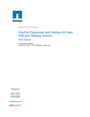
Overview of Cisco Modeling LabsCisco Modeling Labs FrameworkCisco Modeling Labs FrameworkFigure 1: Cisco Modeling Labs FrameworkCisco Modeling Labs 1.0 includes numerous features that enable you to create and simulate small and largenetwork designs. This user guide is organized in a task-based format where the main features are groupedinto four sections referred to as phases.The following items describe each phase which should help you determine which section to refer to whenusing this guide:1 Design—This phase includes the tasks for creating a network topology. You use a blank canvas to createtopologies from scratch or import existing network topologies. You can also view your topologies on ageographic map and adjust where and how interfaces are used on each device.2 Build—This phase includes the tasks associated with configuring routers, external connections, and servers,creating the required configurations, setting up interfaces, IP addressing, and routing protocols for thevirtual routers. There are several ways to create these configurations. You can use the AutoNetKitfunctionality to set up the initial configuration or you can input your own configuration details. Whateverconfigurations you create in this phase will be the configurations that the Cisco Modeling Labs server willuse when it initiates the node simulations.3 Visualization—This phase is optional and operates only if you use AutoNetKit to create your configurationsduring the Build phase. It includes the tasks related to running visualization scenarios of your networkdesign and configuration. It provides visual views of your topology whereby you can see how the nodeswill interact with each other in specific circumstances including physical set up as well as with specificrouting protocols such as ISIS and OSPF. It also supports MPLS and BGP.4 Simulation—This phase includes the tasks for initiating the nodes and making them active. Once thenodes are operational, you can connect to the consoles using Telnet or SSH, as you would connect to arouter console. You can run connectivity tests and modify configurations. This is where the power of theproduct is realized since you can modify and test configurations as if you were on actual physical devices.In this phase, you can also save your configurations and extract them for sharing with others or savingthem and using them as reference when configuring the production network.Cisco Modeling Labs 1.0 User GuideOL-32056-015
Overview of Cisco Modeling LabsCisco Modeling Labs FrameworkCisco Modeling Labs 1.0 User Guide6OL-32056-01
CHAPTER2Using the Cisco Modeling Labs Client Using the Cisco Modeling Labs Client Overview, page 7 Navigating Within the Cisco Modeling Labs Client, page 8 Cisco Modeling Labs Client Components, page 15 Setting Preferences for the Cisco Modeling Labs Client, page 52Using the Cisco Modeling Labs Client OverviewThe Cisco Modeling Labs client is a cross-platform, point-and-click GUI that simplifies topology creation,initial-device configurations, and permits access to the Cisco Modeling Labs server. You can interact directlywith your running simulations from this GUI. Additionally, the Cisco Modeling Labs client provides thefunctionality to generate default router configurations before simulating your topology.This chapter introduces the main areas and capabilities of the Cisco Modeling Labs client in the followingsection.Cisco Modeling Labs 1.0 User GuideOL-32056-017
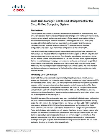
Using the Cisco Modeling Labs ClientNavigating Within the Cisco Modeling Labs ClientNavigating Within the Cisco Modeling Labs ClientThis section describes the functionality of the Cisco Modeling Labs client, which comprises of a workbenchcontaining a menu bar, a toolbar, multiple editors, multiple perspectives, and multiple views.Figure 2: Workbench u Bar5Canvas2Toolbar6Palette3Perspectives7Views4Node Editor5 6combinedTopology Editor Workbench—Refers to the Cisco Modeling Labs client desktop environment. Each time the workbenchis exited, it is automatically saved, including all the open perspectives, views, and editors. When theworkbench is reopened, it appears exactly as it was when last closed. Menu Bar—References all the actions that can be performed when using the Cisco Modeling Labsclient. Toolbar—Contains a set of icons representing commands. The Toolbar provides shortcuts to actionsthat are used most often from the Menu bar. Cisco Modeling Labs Client Perspectives—Identifies the Design and Simulate perspectives, each ofwhich is associated with an initial set of views and editors in your workbench.Cisco Modeling Labs 1.0 User Guide8OL-32056-01
Using the Cisco Modeling Labs ClientMenu Bar From the Design perspective, you can design your network topology, build the node configurations,and check routing protocols. The Design perspective is the default perspective if you are launchingthe Cisco Modeling Labs client for the first time. From the Simulate perspective, you can enable devices and modify configurations to run thesimulations. When the nodes in your topology are fully initialized, you can connect to the consolesas you would connect to a router console. Cisco Modeling Labs Client Editors—Provides alternative components within the Cisco ModelingLabs client from which you can create and edit topologies. Two editors are provided: Node Editor andTopology Editor. The Node Editor shows the interface details for selected elements in the Topology Editor. The Topology Editor is comprised of the Palette view and the canvas. Cisco Modeling Labs Client Views—Provides alternative presentations of your topology, and methodsfor navigating the information in your workbench. Cisco Modeling Labs Client Layout—Enables you to personalize your workbench, allowing you torearrange, resize, reset, and move between views.Menu BarThe menu bar provides access to the complete list of actions that are possible in the Cisco Modeling Labsclient.Cisco Modeling Labs 1.0 User GuideOL-32056-019
Using the Cisco Modeling Labs ClientMenu BarTable 5: Menu Bar ItemsMenuAction(s)FileEnables you to perform actions to a topology project, sub topology, or topology .virl file; setpreferences for resources; and exit the Cisco Modeling Labs client. New—Creates a new topology project folder, topology project, or topology .virl file.See Design a Topology Overview, on page 69 for more information. Save—Saves the current Topology Editor contents. Save As—Saves the current Topology Editor contents to a new file. Print—Prints the current Topology Editor design. Import—Imports a resource type (for example, a topology.virl file) into the CiscoModeling Labs client. See Importing a Topology File, on page 12 for more information. Export—Exports a resource type (for example, a topology.virl file) from the CiscoModeling Labs client. See Exporting a Topology File, on page 12 for more information. Close—Closes the current editor. Close All—Closes all open editors. Preferences—Opens the Preferences dialog box where you can update the settings forthe Cisco Modeling Labs client. See Setting Preferences for the Cisco Modeling LabsClient, on page 52 for more information. Switch Workspace—Allows you to select a workspace folder to use for your session. Exit—Exits the Cisco Modeling Labs client.Cisco Modeling Labs 1.0 User Guide10OL-32056-01
Using the Cisco Modeling Labs ClientMenu BarMenuAction(s)EditEnables you to manipulate resources on the canvas. Undo—Cancels the most recent change. Redo—Applies the most recent change that was removed. Copy—Places a copy of the topology on the clipboard. Paste—Pastes the topology from the clipboard to the canvas at the current cursor location. Delete—Deletes the current topology. Select All—Selects all objects in the current topology canvas. Show Map Background—Displays a map background for the topology. (You musthave Internet access to use this feature.) Reset Note Subtype—Enables you to redefine a virtual node on the canvas. The nodesubtype installed with Cisco Modeling Labs is Cisco IOS. When Reset all interfacenames is selected, the interface IDs are reset sequentially, starting from the Minimumrange. Highlight Connection—Highlights all connections to and from the selected node. Distribute Nodes—Aligns the nodes on the canvas evenly, either vertically orhorizontally, or places them in a grid layout. (This feature is disabled when Show MapBackground is chosen.) Layout Nodes—Places nodes on the canvas in a tree layout or an F-R layout. (Thisfeature is disabled when Show Map Background is selected.) Alignment—Aligns the nodes on the canvas. Options are: left, center, right, top, middle,or bottom. (This feature is disabled when Show Map Background is selected.) Group to Site—Groups two or more nodes within a site.NoteSites are created within Caridenimports. Ungroup to Site—Ungroups nodes from within a site, removing one layer of nesting.ViewEnables you to see numerous perspectives within the Cisco Modeling Labs client. Lists the view options for the selected perspective within the Cisco Modeling Labs client. Allows you to filter your view results.ZoomProvides zoom in and zoom out functionality from within the canvas.RunEnables you to start and stop simulations, and to generate node configurations.SearchEnables you to perform topology searches and text searches within workspaces, topologyprojects, files, and working sets.Cisco Modeling Labs 1.0 User GuideOL-32056-0111
Using the Cisco Modeling Labs ClientMenu BarMenuAction(s)HelpDisplays the help topics for using the Cisco Modeling Labs client in a separate browser window. Help Contents—Opens the Cisco Modeling Labs client support documentation. Cheat Sheets—Helps you complete a task. Generate Problem Report—Generates a detailed report of a problem, which can besubmitted to Cisco Technical Assistance Center (Cisco TAC) for further investigation.See Generating Problem Reports, on page 13 for more information. About Cisco Modeling Labs—Identifies version information and displays detailspertaining to software installations.Importing a Topology FileStep 1From the menu bar, choose File Import.The Import dialog box appears.Step 2From the drop-down list, choose Topology Import Topology file from File System, and click Next.Step 3Click Browse to locate the applicable .virl file.Step 4Step 5In the right pane, check the check box for the applicable .virl file.Click Finish to import the topology file.Exporting a Topology FileStep 1From the menu bar, choose File Export.NoteTo export a topology file, it must be open on the canvas of the Topology Editor.The Export dialog box appears.Step 2From the drop-down list, choose Topology Export Topology file to File System, and click Next.Step 3Click Browse to select the directory to export the topology file to.Step 4Click Finish to export the topology file.Cisco Modeling Labs 1.0 User Guide12OL-32056-01
Using the Cisco Modeling Labs ClientToolbarGenerating Problem ReportsThe Cisco Modeling Labs client provides functionality that allows you to generate problem reports for anyproblems encountered in your topology. It is accessible from the menu bar under Help Generate ProblemReport.While all options are pre-selected, you can individually select the information you want to include in thereport.NoteWhen generating a problem report for your topology, you must have the topology containing the problemopen on the canvas.OptionDescriptionLog FileUser interface .log file from the user's workspace.Consoles ContentCurrent content from the Console view messages. These are messagesfrom the server in response to AutoNetkit and simulation launch actions.Topology Editor ContentsContents of the currently open topology file in the Topology Editor canvas.Screenshot of the User Interface Screenshot showing the state of the user interface when the problemoccurred.Web Services SettingReport of the Web Services details and errors.Additional InformationAny additional information that users can provide to describe the problem.The generated problem report is saved to a .zip file where you can check the contents before sending it to theCisco Technical Assistance Center (Cisco TAC) for investigation.ToolbarThe toolbar is a compilation of icons representing commonly used actions. The toolbar is arranged below themenu bar and offers the same actions as the menu bar, in a single click. The following table outlines the actionsthat can be performed using the Cisco Modeling Labs client toolbar.IconFunctionDescriptionNew TopologyProjectCreates a new topology project. A topology project isa folder in which multiple topology files are stored. Ifyou create many different topolo
Overview of Cisco Modeling Labs Cisco Modeling Labs Component Requirements. Table 3: Client Hardware Requirements Requirement Description Eitherofthefollowing: MicrosoftWindows Windows7or Windows8 AppleMacOSX MacOSX10.8