Transcription
1
Soares Book onGrounding and BondingTwelfth editionInternational Association of Electrical InspectorsRichardson, Texas
Copyright 1966, 1982, 1987, 1990, 1993, 1996, 1999, 2001, 2004, 2008, 2011, 2014 byInternational Association of Electrical Inspectors901 Waterfall Way, Suite 602Richardson, TX 75080-7702All rights reserved. First edition published 1966Printed in the United States of America17 16 15 145 4 3 2 tos used in this book were shot in situ or at tradeshows. Use of the photos does not imply endorsementby IAEI of the manufacturers or the products. Photos without a credit line are from IAEI Archives.4Soares Book on Grounding and Bonding
Notice to the ReaderThis book has not been processed in accordance with NFPA Regulations Governing Committee Projects. Therefore, the text and commentary in it shall not be considered the official position of the NFPAor any of its committees and shall not be considered to be, nor relied upon as a formal interpretationof the meaning or intent of any specific provision or provisions of the 2014 edition of NFPA 70, National Electrical Code. 1Publishers do not warrant or guarantee any of the products described herein or perform any independent analysis in connection with any of the product information contained herein. Publisher does not assume, and expressly disclaims, any obligation to obtain and include information referenced in this work.The reader is expressly warned to consider carefully and adopt all safety precautions that might be indicated by the activities described herein and to avoid all potential hazards. By following the instructionscontained herein, the reader willingly assumes all risks in connection with such instructions.The publishers make no representations or warranties of any kind, including, but not limited to, the impliedwarranties of fitness for particular purpose, merchantability or non-infringement, nor are any such representations implied with respect to such material. The publishers shall not be liable for any special, incidental, consequential or exemplary damages resulting, in whole or in part, from the reader’s uses of or reliance upon thismaterial.National Electrical Code and NEC are registered trademarks of the National Fire Protection Association,Inc., Quincy, MA 02169.15
Table of ContentsChapter 1General Fundamentals10Chapter 2To Ground or Not To Ground40Chapter 3Grounding Electrical Systems60Chapter 4Grounding Electrical Services76Chapter 5Main Bonding Jumpers and Bonding at ServicesChapter 6The Grounding Electrode System112Chapter 7Grounding Electrode Conductors138Chapter 8Bonding Enclosures and Equipment 160Chapter 9Equipment Grounding ConductorsChapter 10Enclosure and Equipment Grounding 208Chapter 11Clearing Ground Faults and Short Circuits 226Chapter 12Grounding Separately Derived Systems 254Chapter 13Grounding and Bonding at Buildings or Structures Suppliedby Feeders or Branch Circuits 276Chapter 14Ground-Fault Protection 290Chapter 15Grounding and Bonding for Special Locations and Conditions 316Chapter 16Grounding and Bonding for Electronic Equipment 368Chapter 17Low-Voltage and Intersystem Grounding and BondingChapter 18Grounding of Systems or Circuits of Over 1kVChapter 19Fundamentals of Lightning ProtectionChapter 20Tables 448Appendix AOrigin of Concrete-Encased Electrode 467Appendix BNational Electrical Grounding Research ProjectAppendix CMetric Conversion ReferenceIndex485941823864084244684767
PrefaceThis book is dedicated to the memory of Eustace C. Soares, P.E., one of the most renownedexperts in the history of the National Electrical Code in the area of grounding electrical systems.A wonderful teacher and man of great vision, Eustace foresaw the need for better definitions toclear up to the great mystery of grounding of electrical systems.Eustace Soares’ book, Grounding Electrical Distribution Systems for Safety was originally publishedin 1966 and was based upon the 1965 edition of the National Electrical Code. Over the years, thisbook has become a classic.A great majority of the recommendations contained in the original edition of his book havebeen accepted as part of Article 250 of the National Electrical Code. The grounding philosophiesrepresented in the original edition are just as relevant today as they were then. To say that Eustacecontributed more than any other man to solving some of the mysteries of grounding of electricalsystems would not be an overstatement of fact. Previous editions have been extensively revisedboth in format and in information. An effort has been made to bring this work into harmonywith the 2014 edition of the National Electrical Code and to retain the integrity of the technicalinformation for which this work has been well known, at the same time adding additionalinformation which may be more recent on the subject of grounding and bonding.IAEI acquired the copyright to Soares’ book in 1981 and published the second edition underthe title Soares Grounding Electrical Distribution Systems for Safety. IAEI acknowledges thecontributions of Wilford I. Summers to editions two and three, and J. Philip Simmons as theprincipal contributor in the revision of the fourth through seventh editions. IAEI acknowledgesMichael J. Johnston as the principal contributor in the revision of the eighth, ninth, and tentheditions. The principal contributors to the revision of the eleventh and twelfth editions wereCharles F. Mello and L. Keith Lofland.IAEI intends to revise this work to complement each new edition of the National Electrical Codeso this will be an on-going project. Any suggestions for additional pertinent material or commentsabout how this work could be improved upon would be most welcome.9
1ChapterGeneralFundamentals101010SoaresBook on Groundingand BondingSoares Bookon Groundingand Bonding
11C hap te rObjectives to understand.···Fundamentals and purpose ofgrounding of electrical systemsDefinitions relative to groundingequipment from grounded andungrounded systemsEffects of electric shock hazards··Purpose of grounding and bondingShort circuit vs. ground faultsin electrical systems·F·Circuit impedance and othercharacteristics·Basic electrical circuit operationOhm’s Lawrom the beginning, the use of electricity has presentedmany challenges ranging from how to install a safe electrical system to how to develop minimum Code requirements for safe electrical installations. These installations dependon several minimum requirements, many of which are covered inNFPA 70, National Electrical Code, Chapter 2, Wiring and Protection. Understanding the protection fundamentals and performancerequirements in Chapter 2 is essential for electrical installation, design, and inspection. To truly understand how and why things workas they do, one must always start with the basics. It is importantthat basic electrical circuits be understood, because grounding andbonding constitute an essential part to a safe electrical circuit. Theprocess of grounding and bonding creates safety circuits that worktogether and are associated with the electrical circuits and systems.The material in this book analyzes the how and why of thesetwo functions of grounding and bonding and expresses their purpose in clear and concise language. It also examines groundingand bonding in virtually every article of the Code in addition tothe major requirements of Article 250. Further, it provides information on grounding and bonding enhanced installations that exceed the minimum NEC requirements, such as for dataChapter 1 — General Fundamentals11
processing facilities and sensitive electronic equipment installations. Chapter seventeen expandsthe information about those types of installationsthat are designed to exceed the Code requirements. It covers establishing an enhanced groundingelectrode system or earthing system and installingfeeders and branch circuits in a fashion that helpsreduce the levels of electrical or electromagneticinterference (EMI) noise on the grounding circuits.This is accomplished though insulation and isolationof the grounding circuit as it is routed to the original grounding point at source of supply (service orsource of separately derived system).Some definitions of electrical terms that shouldbe understood as they relate to the performance ofgrounding and bonding circuits are also included inthis first chapter. This book emphasizes the properand consistent use of the defined terms in both theelectrical field and the NEC in order to develop acommon language of communication.Taking the Mystery Out of GroundingFor many years the subjects of grounding and bonding have been considered the most controversialand misunderstood concepts in the National Electrical Code. Yet there is no real reason why these subjects should be treated as mysteries and given somany different interpretations. Probably the singlemost effective method for clearing up the confusion is for one to review and clearly understand thedefinitions of the various elements of the groundingsystem. In addition, these terms should be usedcorrectly during all discussions and instruction onthe subject so that everyone will have a commonunderstanding. For example, using the term groundwire to mean an equipment grounding conductordoes no more to help a person understand whatspecific conductor is being referenced than doesthe use of the term vehicle when one specificallymeans a truck.It is recommended that the reader carefullyreview the terms defined at the beginning of eachchapter in order to develop or reinforce a clear understanding of how those terms are used in regardto that particular aspect of the subject. Also, manyof the terms associated with the overall grounding12system are illustrated to give the reader a graphic orpictorial understanding of their meaning. It shouldbe noted that the graphics in this text are designedto illustrate a specific point and that not all conductors or details required for a fully compliant installation are necessarily shown.This book is intended to assist the reader inestablishing a strong understanding of the fundamentals of and reasons for the requirements ofgrounding and bonding to attain the highest level ofelectrical safety for persons and property. AppendixA provides information on the origin of concrete-encased electrodes. Appendix B provides a short history of the National Electrical Grounding ResearchProject. IAEI is committed to providing the highestquality information on grounding and bonding tothe electrical industry and hopes that the readerbenefits immensely from this volume.Definitions of Electrical TermsThe following terms are not in alphabetical order;instead, they are sequenced on how the conceptsare taught in logic starting with what pushes current, what current is, and then what impedes thatcurrent flow from dc then ac circuits.Voltage (Electromotive Force). A volt is theunit of measure of electromotive force (EMF). Itis the unit of measure of the force required to establish and maintain electric currents that can bemeasured. By international agreement 1 volt is theamount of EMF that will establish a current of 1amp through a resistance of 1 ohm.Current (Amperes). Current, measured in amperes, consists of the movement or flow of electricity. In most cases, the current of a circuit consistsof the motion of electrons, negatively charged particles of electricity.Impedance. The term resistance is often usedto define the opposition to current in both ac anddc systems. The correct term for opposition to current in ac systems is impedance. Resistance, inductive reactance, and capacitive reactance all offeropposition to current in alternating-current circuits.The three elements are added together vectorially(phasorially), not directly. This results in the totalimpedance or opposition to current of an AC circuit.Soares Book on Grounding and Bonding
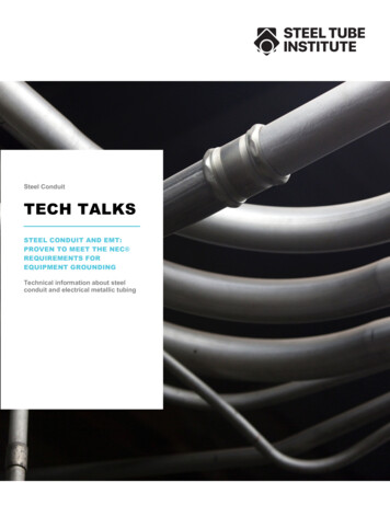
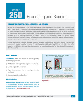
1Impedance is measured in ohmsand provide a solid structural connection to theResistance. Resistance is the name given toearth on which it sits. If the building or structurethe opposition to current offered by the internaldoes not sit on a solid foundation, there can bestructure of the particular conductive material to thecontinuous structural problems that might lead tounsafe conditions. Likewise, the electrical groundmovement of electricity through it, i.e., to the maintenance of current in them. This opposition results in ing system serves as the foundation for an electricalservice or distribution system supplying electricalthe conversion of electrical energy into heat.energy to the structure. Often the grounding ofCapacitance. A capacitor basically consists ofa system or metal objects is referred to as earthtwo conductors that are separated by an insulator.ing, being connected to the earth. When solidlyA capacitor stores electrical stress. Capacitive regrounded, the electrical system must be connectedactance is the opposition to current due to capacito a dependable grounding electrode or groundingtance of the circuit. The Institute of Electrical andelectrode system without adding any intentionalElectronics Engineers (IEEE) defines capacitance as,impedance. The grounding electrode(s) supports“The property of systems of conductors and dielecthe entire grounding system and makes the earthtrics which permits the storage of electricity whenpotential difference exists between the conductors.” connection. It must be effective and all groundingpaths must be connected to it. This serves as theInductance. Inductance is the ability to storefoundation of the electrical system. Chapter sixmagnetic energy. Inductance is caused by thecovers the grounding electrodes, their functions,magnetic field of an alternating-current circuit asand their installations.a result of the alternating current changing directions. This causes the magnetic lines of force thatsurround the conductor to rise and fall. Induction is Electrical Circuitry Basicsmeasured as inductive reactance. As the magneticAnyone who has been involved in the electricallines of force rise and fall, they work to oppose thefield for any length of time has heard the phrase,conductor and induce a voltage directly opposite“Electricity takes the path of least resistance.” Fromthe applied voltage. This induced voltage is called counterSeries and Parallel Paths for Currentelectromotive force or counterEMF. Induction is the currenteffect of an ac circuit. Wherethere is an alternating magneticfield there will be induction.This induction will result ininductive reactance, which opposes the current.The Foundation ofGroundingThe first and most vital elementof a sound, safe structure is asolid footing or foundation onwhich to build the building.This foundation, usually consisting of concrete and reinforcingbars, must be adequate to support the weight of the buildingChapter 1 — General FundamentalsFIGURE 1.1 Series and parallel paths for current13
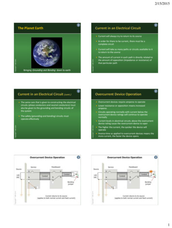
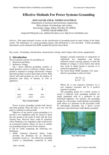
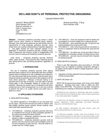
(push) current or intensity(I) through a resistance (R).These are the basic components of Ohm’s law (seeOhm’s law and its derivatives in Watt’s wheel in figure 1.2). Electrical currentcan be compared with waterflowing through a water pipe.With the pressure being thesame, the bigger the pipe,the less the resistance is tothe flow of water throughthe pipe. The smaller thepipe, the greater the resistance is to the flow of waterthrough it. The same holdstrue for electrical current.Larger electrical conductors(paths) offer lower resistance to current. Smallerelectrical conductors (paths) offer greater resistanceto current. There must be a complete circuit orpath and a voltage (difference of potential) or therewill be no current. This is true of both normal current and fault current.Watt’s Wheel – Ohm’s LawFIGURE 1.2 Watt’s wheel—current in a circuitgrade school science class to the first-year apprentice to the seasoned veteran of the industry,the phrase is used to describe the path electricalcurrent will take. The phrase is stated with pride,“Electricity takes the path of least resistance” or“Current takes the path of least resistance,” and usually not much thought is given as to what is reallygoing on. In reality, current will take all paths orcircuits that are available. Where more than onepath exists, current will divide among the paths(see figure 1.1). As we will review later, current willdivide in opposite proportion to the impedance.The lower impedance path or circuit will carrymore current than the higher impedance path(s).The study of grounding and bonding is vital to applying basic rules relative to this important safetyelement of the electrical circuit. It is important toreview some basic principles and the fundamentalelements of electricity and how current relates toelectrical safety.Ohm’s Law in ReviewBefore we can have current flowing, there needsto be a complete circuit (see the circuit diagram infigure 1.2). The amount of current in an electricalcircuit depends on the characteristics of the circuit. Voltage or electromotive force (E) will cause14Resistance as Compared to ImpedanceUnderstanding the differences between the pureresistance of an electric circuit and the impedance of a circuit is important in gaining a thoroughunder-standing of the grounding or safety circuit. InOhm’s law, resistance is the total opposition to current in a dc circuit. In an alternating-current circuit,the total opposition to current is the total impedance comprised of three components. The impedance (Z) of an ac circuit is the inductive reactance,capacitive reactance, and the resistance addedtogether vectorially (phasorially) [see formula infigure 1.3]. In a 60-cycle ac circuit, alternating current changes amplitude and direction 120 timesper second and develops a magnetic field thatresults from the inductive reactance of the circuit.Therefore, minimizing the amount of the overallopposition (impedance) to current in the groundingand bonding circuits of electrical systems is veryimportant. These circuits can be looked upon as si-Soares Book on Grounding and Bonding
1Basic Electrical Theory Terms(1) the path for ground-faultcurrent must be electricallycontinuous; (2) it must haveadequate capacity to conduct safely any ground-faultcurrent likely to be imposedon it; and (3) it must be oflow impedance (see figure1-26 and chapter eleven formore specific informationrelative to clearing groundfaults and short circuits).Article 250 mentionsthe term low-impedancepath several times. As aquick overview, the opposition to current in a dc circuit is resistance. The totalopposition to current inan ac circuit is impedance.FIGURE 1.3 Basic electrical theory terms and formulas, including basic formulas for accircuit resistance and impedanceWhen the phrase “lowimpedance path” is usedlent servants, just waiting to perform the importantin the Code, it is referring to a path that offers littlefunction of carrying enough current so overcurrentopposition to current whether it is normal currentprotective devices can operate to clear a fault.or fault current. The key element is ensuring thereis low opposition or impedance to the flow of theCurrent in a Circuitcurrent.In any complete circuit or path that is available, current—be it normal current or fault current—willOvercurrent Device Operationalways try to return to its source. The statement onOvercurrent devices operate because of moretaking the path of least resistance is partially corcurrent (amps) flowing than the device is ratedrect. Electrical current will take any and all availableto carry. Generally speaking, the more currentpaths to return to its source (see figures 1.1 and 1.5).through overcurrent devices above their ratingIf several paths are available, current will divide andthe faster they open or operate; this is becausethe resistance or the impedance of each path willthey are designed to operate in inverse time.determine how much current is on that particularRelative to the discussion about impedance, thepath. It can be concluded from the above that ifhigher the impedance of the path, the lowerthere is no complete circuit, then there is no curthe current through the overcurrent device andrent. Care is given to the installation of ungroundedtherefore longer time to open. The lower the(phase or hot) conductors so that the circuit will beimpedance of the path, the greater is the currentcomplete to provide a suitable path for current durthrough the overcurrent device and faster opening normal operation. The same principles and funing time. Understanding these basic elements ofdamentals apply to the installation of grounding andelectrical circuits helps one apply some imporbonding conductors that make up the safety circuits. tant rules in Article 250. The following examplesThe equipment grounding (safety) circuit must beclearly demonstrate that amps operate overcurcomplete and must meet three important criteria:rent devices (see figures 1.6 and 1.7.Chapter 1 — General Fundamentals15
Overcurrent Device OperationFIGURE 1.4 Proper grounding and bonding facilitates theoperation of overcurrent devices.As with the electrical circuit installed fornormal current, the equipment grounding (safety)circuit must also be installed for abnormal current to ensure overcurrent device operation inground-fault conditions. The equipment grounding or safety circuit must be complete and constructed with as little impedance as practicablefor quick, sure overcurrent device operation.Care must be taken when installing electricalsystems and circuits, including the equipmentgrounding and bonding circuits of the system.Where the human body gets involved in the circuit it can, or often, results in an electrical shockor even electrocution in some cases. The humanbody introduces a relatively high level of impedance that impacts the overcurrent device operation. Ground-fault circuit interrupters provide adegree of protection from electrical shock, butstandard overcurrent devices do not. Later in thischapter is a discussion about shock hazards andeffects on the human body, and chapter fourteenprovides more information about ground-faultcircuit interrupters.Proper Language of CommunicationA common language of communication hasbeen established to enable one to understandthe requirements of the NEC, in general, and ofgrounding and bonding, in particular. A common16FIGURE 1.5 Current will try to return to its source (normal andfault current work the same way)Normal Current in the CircuitFIGURE 1.6 Normal electrical circuit (normal current in circuit)set of terms, defining and explaining the functionof the terms as used in the Code, is included inArticle 100 and in sections xxx.2 of other articles.Two conductors of grounding grounded systemshould be mentioned and a brief story told abouteach: the grounded conductor and the equipmentgrounding conductor.Soares Book on Grounding and Bonding
1Bonding and Grounding TerminologyIAEI’s Soares Book on Grounding and Bonding places a huge emphasis on definitions ofwords and terms used for proper applicationof Code rules relating to the subject of grounding and bonding. Using a common language ofcommunication is imperative to understandingthis subject, and applying the Code to installations and systems in the field as clearly indicatedin chapter one of this book. It is important thatwords and terms related to this subject meanwhat they imply by definition for all code users.the use of these terms is uniform and consistentthroughout the NEC. The work of this taskgroup resulted in simply changing the meaning of defined grounding and bonding terms toimprove clarity and usability within the NEC requirements where they are used. Code rules thatuse defined grounding and bonding terms wererevised as needed to clarify the meaning of therule and to ensure that these terms are usedconsistently with how they are defined in Article 100 and at 250.2. In many instances, ruleswere revised to become more prescriptive forNEC Grounding and Bonding Revisionscode users to provide clear direction on whatIn recent editions of the Code, there have beenis intended to be accomplished from a perfornumerous revisions to many of the groundingmance standpoint. As an example, many rulesand bonding terms used in the NEC. These revithroughout the Code used the phrase “shall besions were the result of significant efforts of agrounded,” which was replaced with the phrasespecial task group assigned by the NEC Technical “shall be connected to an equipment groundingCorrelating Committee. The primary objective ofconductor.” This simple revision will relay to thethis task group was to ensure accuracy of defined code user that a certain object not only needsterms related to grounding and bonding, difto be grounded, but more importantly, “how”ferentiate between the two concepts, and verifythe object is to be grounded.SIDEBAR 01.1 Bounding and Grounding TerminologyGround-Fault Current in the CircuitFIGURE 1.7 Electrical circuit with ground fault to enclosureChapter 1 — General FundamentalsGrounded and GroundedConductorThe grounded conductor (usuallya neutral) is generally a systemconductor intended to carry current during normal operationof the circuit. The connectionto ground (earth) of the systemgrounded (often a neutral) conductor is accomplished by aconnection through a groundingelectrode conductor either at theservice or at a separately derivedsystem. Generally, it should beunderstood that the groundedconductor should not be used forgrounding of equipment on theload side of the system grounding17
Grounded (Grounding)Grounding and EquipmentGrounding ConductorAs used in Article 250 and otherarticles, grounding is a processthat is ongoing. The conductor tolook at is the equipment groundingconductor. The action is ongoingthrough every electrical enclosureit is connected to all the way tothe last outlet on the branch circuit.The equipment grounding conductor provides a low-impedance pathfor fault-current if a ground faultshould occur in the system andalso connects all metal enclosuresto the grounding point of the service or system.FIGURE 1.8 Grounding connects equipment and systems to ground (the earth).So it is important that theequipmentgroundingconductor make a completeconnection at the service or source of separatelyand reliable circuit back to the source. At the serderived systems. This separation between groundedviceis where the grounded (neutral) conductor andconductors and equipment grounding conducthe equipment grounding conductor(s) are requiredtors keeps the normal return current on the neutralto be connected together through a main bonding(grounded) conductor of the system, where it bejumper. In a separately derived system, this conlongs, when returning to its source. These principlesare reinforced by requirements in 110.7, 250.24(A)(5) nection is made with a system bonding jumperinstalled between the grounded conductor andand 250.30(A). Code rules and requirements for thethe equipment grounding conductor(s). The maingrounded conductors are covered in depth in chapbonding jumper and the system bonding jumperter three of this text.complete the ground fault-currentBonded (Bonding)circuit back to the source. Therules and requirements for equipment grounding conductors arecovered in depth in chapter nine.Grounding as Comparedto BondingFIGURE 1.9 Bonding (bonded) establishes electrical continuity and conductivity.18Defined in Article 100, both ofthese functions are essential for thecomplete safety anticipated by therules in Article 250 (see figure 1.10).Ground. “The earth.”Grounded (Grounding). “Connected (connecting) to ground or toa conductive body that extends theground connection” (see figure 1.8).Bonded (Bonding). “Con-Soares Book on Grounding and Bonding
1Grounding Compared to Bondingelementary. Current, be it normalcurrent or fault current, will takeall the paths available to it totry to return to its source. If thegrounded conductor (neutral) andequipment grounding conductorsare connected at points downstream of the service or separatelyderived system, such as at subpanels, multiple paths will beavailable on which the currentwill try to return to the source.This can lead to normal neutralcurrent on water piping systems,conduit, wire-type equipmentgrounding conductors, and anyFIGURE 1.10 Grounding compared to bonding showing the connection to earth atother electrically conductivethe source (utility) and service and everything bonded to that point of groundingpaths, and all these extra pathsnected to establish electrical continuity andcan compromise electrical safetyconductivity” (see figure 1.9).and even proper overcurrent device operation inThese are two separate functions with two difground-fault conditions.ferent purposes. It is important to establish a clearIn recent editions of the NEC (1996), electricunderstanding of the grounding (earthing) circuit and range and dryer circuits were required to include anits purpose as compared to the equipment groundequipment grounding conductor in addition to aning conductors and bonding jumpers or connections. insulated grounded conductor. Existing range andSection 250.4 has been broken down intodryer circuits are allowed to continue the use of thegrounded systems and ungrounded systems. Regrounded conductor, or neutral, to ground the boxesquirements in this section include descriptive perat the outlet and the frames of the equipment. Newformance requirements and establish the purposesinstallations, however, are required to maintain isolaserved by each of these actions. The title of Artion (insulation) between the grounded conductorticle 250 is “Grounding and Bonding.” The articleand the equipment grounding conductor.contains an equally strong emphasis on bondingThe rules covering the use of the groundedrequirements. Chapter eight presents detailedconductor for equipment grounding purposes at ainformation on these bonding requirements (seesecond building or struct
12 Soares Book on Grounding and Bonding processing facilities and sensitive electronic equip-ment installations. Chapter seventeen expands the information about those types of installations that are designed to exceed the Code require-ments. It