Transcription
International Association of Electrical InspectorsIAEI13th EditionSOARESGrounding & BondingNEC 2017
Soares Groundingand BondingThirteenth edition
Soares Book onGrounding and BondingThirteenth editionInternational Association of Electrical InspectorsRichardson, Texas
Copyright 1966, 1982, 1987, 1990, 1993, 1996, 1999, 2001, 2004, 2008, 2011, 2014, 2017 byInternational Association of Electrical Inspectors901 Waterfall Way, Suite 602Richardson, TX 75080-7702All rights reserved. First edition published 1966Printed in the United States of America21 20 19 18 175 4 3 2 1ISBN-10: 1-890659-73-8ISBN-13: 978-1-890659-73-8Photos used in this book were shot in situ or at tradeshows. Use of the photos does not imply endorsement byIAEI of the manufacturers or the products. Photos without a credit line are from IAEI Archives.4Soares Grounding & Bonding
Notice to the ReaderThis book has not been processed in accordance with NFPA Regulations Governing Committee Projects.Therefore, the text and commentary in it shall not be considered the of ficial position of the NFPA or any ofits committees and shall not be considered to be, nor relied upon as a formal interpretation of the meaningor intent of any specific provision or provisions of the 2017 edition of NFPA 70, National Electrical Code. 1Publishers do not warrant or guarantee any of the products described herein or perform any independentanalysis in connection with any of the product information contained herein. Publisher does not assume, andexpressly disclaims, any obligation to obtain and include information referenced in this work.The reader is expressly warned to consider carefully and adopt all safety precautions that might be indicatedby the activities described herein and to avoid all potential hazards. By following the instructions containedherein, the reader willingly assumes all risks in connection with such instructions.The publishers make no representations or warranties of any kind, including, but not limitedto, the implied warranties of fitness for particular purpose, merchantability or non-infringement, nor are any such representations implied with respect to such material. The publishersshall not be liable for any special, incidental, consequential or exemplary damages resulting, inwhole or in part, from the reader’s uses of or reliance upon this material.National Electrical Code , NFPA 70E , and NEC are registered trademarks of the National Fire Protection Association, Inc., Quincy, MA 02169.1National Fire Protection Association, NFPA 780-2017, “Standard for the Installation of Lightning ProtectionSystems,” (Quincy, MA: National Fire Protection Association, 15 August 2010).5
Table of Contents1.General Fundamentals102.To Ground or Not to Ground393.Grounding Electrical Systems564.Grounding Electrical Services715.Main Bonding Jumpers and Bonding at Services866.The Grounding Electrode System1037.Grounding Electrode Conductors1268.Bonding Enclosures and Equipment1479.Equipment Grounding Conductors16610.Enclosure and Equipment Grounding19011.Clearing Ground Faults and Short Circuits20612.Grounding Separately Derived Systems23013.Grounding and Bonding at Buildings or Structures Supplied byFeeders or Branch Circuits24914.Ground-Fault Protection26015.Grounding and Bonding for Special Locations28116.Grounding and Bonding for Special Conditions30617.Grounding and Bonding for Alternate Energy Systems32618.Grounding and Bonding for Electronic Equipment33819.Low-Voltage and Intersystem Grounding and Bonding35520.Grounding of Systems or Circuits of Over 1000 Volts37621.Fundamentals of Lightning Protection39022.Tables414Appendix AAppendix BAppendix COrigin of Concrete-Encased ElectrodeNational Electrical Grounding Research ProjectMetric Conversion Reference4334344427
PrefaceThis book is dedicated to the memory of Eustace C. Soares, P.E., one of the most renowned experts in thehistory of the National Electrical Code in the area of grounding electrical systems. A wonderful teacherand man of great vision, Eustace foresaw the need for better definitions to clear up to the great mystery ofgrounding of electrical systems.Eustace Soares’ book, Grounding Electrical Distribution Systems for Safety was originally published in 1966and was based upon the 1965 edition of the National Electrical Code. Over the years, this book has become aclassic.A great majority of the recommendations contained in the original edition of his book have been acceptedas part of Article 250 as well as many other sections of the National Electrical Code . The groundingphilosophies represented in the original edition are just as relevant today as they were then. To say thatEustace contributed more than any other man to solving some of the mysteries of grounding of electricalsystems would not be an overstatement of fact. Previous editions have been extensively revised both informat and in information. An effort has been made to bring this work into harmony with the 2017 editionof the National Electrical Code and to retain the integrity of the technical information for which thiswork has been well known, at the same time adding additional information which may be more recent onthe subject of grounding and bonding. The 13th edition was again revised to provide a better flow of theinformation closer to what designers and installers will experience in an actual project.IAEI acquired the copyright to Soares’ book in 1981 and published the second edition under the title SoaresGrounding Electrical Distribution Systems for Safety. IAEI acknowledges the contributions of Wilford I.Summers to editions two and three, and J. Philip Simmons as the principal contributor in the revision of thefourth through seventh editions. IAEI acknowledges Michael J. Johnston as the principal contributor in therevision of the eighth, ninth, and tenth editions. The principal contributors to the revision of the eleventh,twelfth, and thirteenth editions were Charles F. Mello and L. Keith Lofland.IAEI intends to revise this work to complement each new edition of the National Electrical Code so this willbe an on-going project. Any suggestions for additional pertinent material or comments about how this workcould be improved upon would be most welcome.9
Chapter 1GeneralFundamentalsObjectives to understand 10Fundamentals and purpose of grounding ofelectrical systemsDefinitions relative to grounding equipmentfrom grounded and ungrounded systemsEffects of electric shock hazardsPurpose of grounding and bondingShort circuit vs. ground faults in electrical systemsCircuit impedance and other characteristicsBasic electrical circuit operationOhm’s LawFrom the beginning, the use of electricityhas presented many challenges rangingfrom how to install a safe electrical systemto how to develop minimum Code requirements for safe electrical installations.These installations depend on several minimum requirements, many of which are covered in NFPA 70,National Electrical Code, Chapter 2, Wiring and Protection. Understanding the protection fundamentals andperformance requirements in Chapter 2 is essential forelectrical installation, design, and inspection. To trulyunderstand how and why things work as they do, oneSoares Grounding & Bonding
1must always start with the basics. The first part of basicsis understanding and properly using the terminologyfor grounding and bonding. Unless the terms used areclearly understood, misunderstandings and confusionwill prevail. It is important that basic electrical circuitsbe understood because grounding and bonding constitute an essential part to a safe electrical circuit. Theprocess of grounding and bonding creates safety circuitsthat work together and are associated with the electricalcircuits and systems that control and supply electricityto equipment.The material in this book analyzes the how andwhy of these two functions of grounding and bonding and expresses their purpose in clear and conciselanguage. It also examines grounding and bondingin virtually every article of the Code in addition tothe major requirements of Article 250. Further, itprovides information on grounding and bonding enhanced installations that exceed the minimum NECrequirements, such as for data processing facilities andsensitive electronic equipment installations. Chaptereighteen expands the information about those typesof installations that are designed to exceed the Coderequirements. It covers establishing an enhancedgrounding electrode system or earthing system andinstalling feeders and branch circuits in a fashion thathelps reduce the levels of electrical or electromagneticinterference (EMI) noise on the grounding circuits.This is accomplished though insulation and isolationof the grounding circuit as it is routed to the originalgrounding point at the source of supply (service orsource of separately derived system).Some definitions of electrical terms that should beunderstood as they relate to the performance of grounding and bonding circuits are also included in this firstchapter. This book emphasizes the proper and consistent use of the defined terms in both the electrical fieldand the NEC in order to develop a common language ofcommunication.Taking the Mystery Out of GroundingFor many years the subjects of grounding and bondinghave been considered the most controversial and misunderstood concepts in the National Electrical Code.Yet there is no real reason why these subjects should betreated as mysteries and given so many different interpretations. Probably the single most effective methodChapter 1: General Fundamentalsfor clearing up the confusion is for one to review andclearly understand the definitions of the various elements of the grounding system. In addition, these termsshould be used correctly during all discussions andinstruction on the subject so that everyone will have acommon understanding. For example, using the termground wire to mean an equipment grounding conductordoes no more to help a person understand what specificconductor is being referenced than does the use of theterm vehicle when one specifically means a truck.It is recommended that the reader carefully reviewthe terms defined at the beginning of each chapter inorder to develop or reinforce a clear understanding ofhow those terms are used in regard to that particularaspect of the subject. Also, many of the terms associatedwith the overall grounding system are illustrated to givethe reader a graphic or pictorial understanding of theirmeaning. It should be noted that the graphics in this textare designed to illustrate a specific point and that not allconductors or details required for a fully compliant installation are necessarily shown.This book is intended to assist the reader in establishing a strong understanding of the fundamentalsof and reasons for the requirements of grounding andbonding to attain the highest level of electrical safetyfor persons and property. Appendix A provides information on the origin of concrete-encased electrodes.Appendix B provides a short history of the NationalElectrical Grounding Research Project. IAEI is committed to providing the highest quality information ongrounding and bonding to the electrical industry andhopes that the reader benefits immensely from thisvolume.Definitions of Basic Electrical TermsThe following terms are not in alphabetical order;instead, they are sequenced on how the concepts aretaught in logic starting with what pushes current, whatcurrent is, and then what impedes that current flowfrom dc then ac circuits.Voltage (Electromotive Force). A volt is the unit ofmeasure of electromotive force (EMF). It is the unit ofmeasure of the force required to establish and maintainelectric currents that can be measured. By internationalagreement 1 volt is the amount of EMF that will establish a current of 1 amp through a resistance of 1 ohm.Current (Amperes). Current, measured in amperes,11
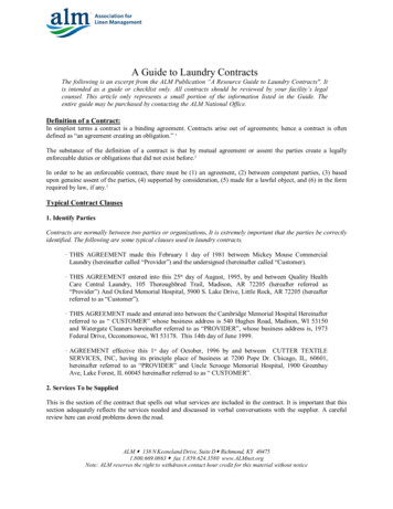
consists of the movement or flow of electricity. In mostcases, the current of a circuit consists of the motion ofelectrons, negatively charged particles of electricity.Resistance (Ohms). Resistance is the name given tothe opposition to current offered by the internal structure of the particular conductive material to the movement of electricity through it, i.e., to the maintenance ofcurrent in them. This opposition results in the conversion of electrical energy into heat.Impedance (Ohms). The term resistance is oftenused to define the opposition to current in both ac anddc systems. The correct term for opposition to currentin ac systems is impedance. Resistance, inductive reactance, and capacitive reactance all offer opposition tocurrent in alternating-current circuits. The three elements are added together vectorially (phasorially), notdirectly. This results in the total impedance or opposition to current of an AC circuit. Impedance is measuredin ohmsCapacitance. A capacitor basically consists of twoconductors that are separated by an insulator. A capacitor stores electrical stress. Capacitive reactance is theopposition to current due to capacitance of the circuit.The Institute of Electrical and Electronics Engineers(IEEE) defines capacitance as, “The property of systemsof conductors and dielectrics which permits the storageof electricity when potential difference exists betweenthe conductors.”Inductance. Inductance is the ability to storemagnetic energy. Inductance is caused by the magneticfield of an alternating-current circuit as a result of thealternating current changing directions. This causesthe magnetic lines of force that surround the conductor to rise and fall. Induction is measured as inductivereactance. As the magnetic lines of force rise and fall,they work to oppose the conductor and induce a voltage directly opposite the applied voltage. This inducedvoltage is called counter-electromotive force or counterEMF. Induction is the current effect of an ac circuit.Where there is an alternating magnetic field there willbe induction. This induction will result in inductive reactance, which opposes the current.The Foundation of GroundingThe first and most vital element of a sound, safe structure is a solid footing or foundation on which to buildthe building. This foundation, usually consisting of concrete and reinforcing bars, must be adequate to supportthe weight of the building and provide a solid structuralconnection to the earth on which it sits. If the buildingor structure does not sit on a solid foundation, there canbe continuous structural problems that might lead tounsafe conditions. Likewise, the electrical groundingsystem serves as the foundation for an electrical serviceor distribution system supplying electrical energy tothe structure. Often the grounding of a system or metalobjects is referred to as earthing, being connected tothe earth. When solidly grounded, the electrical systemmust be connected to a dependable grounding electrodeor grounding electrode system without adding anyintentional impedance. The groundingelectrode(s) supports the entire grounding system and makes the earth connection. It must be effective and all grounding paths must be connected to it. Thisserves as the foundation of the electricalsystem. Chapter six covers the grounding electrodes, their functions, and theirinstallations.Electrical CircuitryBasicsFIGURE 1.1 Series and parallel paths for current12Anyone who has been involved in theelectrical field for any length of timehas heard the phrase, “Electricity takesthe path of least resistance.” From gradeschool science class to the first-yearSoares Grounding & Bonding
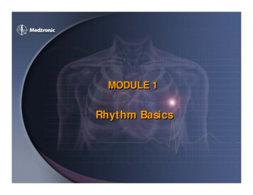
1apprentice to the seasoned veteran of the industry, thephrase is used to describe the path electrical currentwill take. The phrase is stated with pride, “Electricitytakes the path of least resistance” or “Current takes thepath of least resistance,” and usually not much thoughtis given as to what is really going on. In reality, currentwill take all paths or circuits that are available. Wheremore than one path exists, current will divide amongthe paths (see figure 1.1). As we will review later, current will divide in opposite proportion to the impedance. The lower impedance path or circuit will carrymore current than the higher impedance path(s). Thestudy of grounding and bonding is vital to applyingbasic rules relative to this importantsafety element of the electrical circuit. Itis important to review some basic principles and the fundamental elements ofelectricity and how current relates toelectrical safety.Resistance as Compared toImpedanceUnderstanding the differences between the pure resistance of an electric circuit and the impedance ofa circuit is important in gaining a thorough understanding of the grounding or safety circuit. In Ohm’slaw, resistance is the total opposition to current in a dccircuit. In an alternating-current circuit, the total opposition to current is the total impedance comprised ofthree components. The impedance (Z) of an ac circuitis the inductive reactance, capacitive reactance, and theresistance added together vectorially (phasorially) [seeformula in figure 1.3]. In a 60-Hertz ac circuit, alter-Ohm’s Law in ReviewBefore we can have current flowing,there needs to be a complete circuit (seethe circuit diagram in figure 1.2). Theamount of current in an electrical circuitdepends on the characteristics of thecircuit. Voltage or electromotive force(E) will cause (push) current or intensity(I) through a resistance (R). These arethe basic components of Ohm’s law (seeOhm’s law and its derivatives in Watt’swheel in figure 1.2). Electrical currentcan be compared with water flowingthrough a water pipe. With the pressurebeing the same, the bigger the pipe, theless the resistance is to the flow of waterthrough the pipe. The smaller the pipe,the greater the resistance is to the flowof water through it. The same holds truefor electrical current. Larger electricalconductors (paths) offer lower resistanceto current. Smaller electrical conductors(paths) offer greater resistance to current.There must be a complete circuit or pathand a voltage (difference of potential) orthere will be no current. This is true ofboth normal current and fault current.Chapter 1: General FundamentalsFIGURE 1.2 Watt’s wheel—current in a circuitFIGURE 1.3 Basic electrical theory terms and formulas, including basicformulas for ac circuit resistance and impedance13
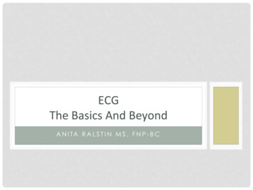
FIGURE 1.4 Proper grounding and bonding facilitates the operation of overcurrent devices.nating current changes amplitude and direction 120times per second and develops a magnetic field thatresults from the inductive reactance of the circuit.In addition, any circuit with insulated conductorsat different instantaneous potentials and a potentialfrom ground will have capacitance and capacitivereactance. Therefore, minimizing the amount ofthe overall opposition (impedance) to current in thegrounding and bonding circuits of electrical systemsis very important. These circuits can be looked uponas silent servants, just waiting to perform the important function of carrying enough current so overcurrent protective devices can operate to clear a fault.This is one reason the Code requires all conductors ofa circuit to be closely installed together, NEC 300.3,to minimize the overall impedance.Current in a CircuitIn any complete circuit or path that is available, current—be it normal current or fault current—will alwaystry to return to its source. The statement on taking thepath of least resistance is partially correct. Electricalcurrent will take any and all available paths to return14to its source (see figures 1.1 and 1.5). If several pathsare available, current will divide and the resistance orthe impedance of each path will determine how muchcurrent is on that particular path. It can be concludedfrom the above that if there is no complete circuit, thenthere is no current. Care is given to the installationof ungrounded (phase or hot) conductors so that thecircuit will be complete to provide a suitable path forcurrent during normal operation. The same principlesand fundamentals apply to the installation of groundingand bonding conductors that make up the safety circuits. The equipment grounding (safety) circuit must becomplete and must meet three important criteria: (1) thepath for ground-fault current must be electrically continuous; (2) it must have adequate capacity to conductsafely any ground-fault current likely to be imposed onit; and (3) it must be of low impedance (see figure 1-26and chapter eleven for more specific information relative to clearing ground faults and short circuits).Article 250 mentions the term low-impedance pathseveral times. As a quick overview, the opposition tocurrent in a dc circuit is resistance. The total opposition to current in an ac circuit is impedance. When theSoares Grounding & Bonding
1phrase “low-impedance path” is usedin the Code, it is referring to a path thatoffers little opposition to current whether it is normal current or fault current.The key element is ensuring there is lowopposition or impedance to the flow ofthe current.Overcurrent DeviceOperationOvercurrent devices operate becauseof more current (amps) flowing thanthe device is rated to carry. Generallyspeaking, the more current throughovercurrent devices above their ratingthe faster they open or operate; this isbecause they are designed to operatein inverse time. Relative to the discussion about impedance, the higher theimpedance of the path, the lower thecurrent through the overcurrent deviceand therefore longer time to open. Thelower the impedance of the path, thegreater is the current through the overcurrent device and faster opening time.Understanding these basic elements ofelectrical circuits helps one apply someimportant rules in Article 250. The folFIGURE 1.5 Current will try to return to its source (normal and fault currentlowing examples clearly demonstratework the same way)that amps operate overcurrent devices(see figures 1.6 and 1.7).As with the electrical circuit installed for normalrent devices do not. Later in this chapter is a discussioncurrent, the equipment grounding (safety) circuit mustabout shock hazards and effects on the human body,also be installed for abnormal current to ensure overand chapter fourteen provides more information aboutcurrent device operation in ground-fault conditions.ground-fault circuit interrupters.The equipment grounding or safety circuit must becomplete and constructed with as little impedance asProper Language ofpracticable for quick, sure overcurrent device operation. CommunicationCare must be taken when installing electrical systemsA common language of communication has been estaband circuits, including the equipment grounding andlished to enable one to understand the requirements of thebonding circuits of the system. Where the human bodyNEC, in general, and of grounding and bonding, in pargets involved in the circuit it can, or often, results in anticular. A common set of terms, defining and explainingelectrical shock or even electrocution in some cases. The the function of the terms as used in the Code, is includedhuman body introduces a relatively high level of imin Article 100 and in sections xxx.2 of other articles. Twopedance that impacts the overcurrent device operation.specific conductors of the electrical circuit should be menGround-fault circuit interrupters provide a degree oftioned and a brief story told about each: the grounded conprotection from electrical shock, but standard overcurductor and the equipment grounding conductor.Chapter 1: General Fundamentals15
IndexAAgricultural buildings 27, 42, 47, 148, 195, 257, 291, 300Alternate energy and distributed generations systemsChapter 17, 326, 394Alternating-current 12, 21, 42, 47, 57, 113, 183, 268, 334,414Amateur transmission and receiving stations 355, 365ANSI/ISA RP 12.06.01-2003, Recommended Practice forWiring Methods for Hazardous (Classified) Locations Instrumentation Part 1: Intrinsic Safety. 357Arc-Fault Circuit Interrupters (AFCI) 261, 269Article 250 11, 14, 17, 20Article 645 338Auxiliary grounding electrode 116, 181, 334, 341, 348BBolted connections 139, 223Bolted faults 52Bonded, Bonding 17, 87, 148, 159, 308Bonding electrodes of different systems 363Differences of potential 363Electrical equipment 27, 147Electrically conductive materials 28, 318Electrode conductor installations 371Equipotential Bonding 317, 406Hazardous (Classified) Locations 282Method 95Multiple Raceway Systems 153Multiple service disconnecting means 99Over 250 Volts 150Patient care areas 207, 298Purpose of 27Receptacles 154Spa or hot tub installed indoors 322Structural steel 159Structural steel and water piping 158Bonding jumper, system 156Main bonding jumper 88, 90Parallel Supply-Side 93Sizing of 92, 111Supply side bonding jumper 92452Broadband grounding systems 345Burns and other injuries 26Busbars 30, 240CCabinets, cutout boxes and wireways 151Cables 172Branch-Circuit Cable 174Nonmetallic-Sheathed Cable 173Service-Entrance Cable 174Type AC Cable 172Type MC Cable 173Capacitance 12Capacitive reactance 12Circuit(s) 12Basics 12Control circuit 356Current 14Direct-current circuits 183Equipment grounding (safety) circuit 16Grounded circuit conductor 185Impedance 13, 22, 34, 141Not to be grounded 46Signaling circuits 356Clean surfaces 136Community antenna television and radio distribution(CATV) systems 366Concrete-encased electrodes 107, 433Ground ring 110Installation 109Size of bonding jumper 111Conductor(s) 564 AWG and larger 596 AWG or smaller 58Bonding conductor or jumper 191, 359Down conductors 400Enclosures 89Flexible cords 59Neutral 94Roof conductors 399Size of grounded conductor 76Soares Grounding & Bonding
Ungrounded service-entrance conductors 80, 128, 379Withstand rating 223ConduitConduit fittings 148, 149Equipment grounding means 219Flexible conduits 284Long Conduit Runs 220Underground 184Cord-connected equipment 314Counter-electromotive force (EMF) 13Current 14, 18Objectionable Currents 120Current (Amperes) 11DDelta bank with a zigzag grounding transformer 63Delta-connected systems 61Designing electrical systems 30Direct current (dc) 22, 334Disconnecting means 56, 65, 71, 78, 99, 130EEarthing 12Electrical shock 24, 26Electrical systems designed 15, 39Electric signs 194, 307Electrolytic grounding systems 115Elevators and cranes 194Equipment bonding jumpers 152Installation 156Equipment ground-fault protective device (EGFPD) 261Equipment grounding conductor 11, 15, 16, 18, 21, 307Cable shield 385Circuit conductors 192Flexible Cord and Fixture Wire 177High frequency effects 347Motor Circuits 177Parallel 77Size 76, 78Equipotential plane 302, 345FFault-Current 28, 209Ferrous metal raceways 140Fuel cell systems 333IndexGGarages, theaters, and motion picture studios 194Grid Connected System 329Ground 17Ground-detection indicator systems 48Grounded (Grounding) 11, 21, 27, 57, 61AC systems of 50 to 1000 volts 42Alternating-current systems of over 1000 volts 43Alternatives to 20Building steel 183Communications cable 363Cord- and plug-connected equipment 195Data processing system 344Electrical equipment 27, 342Electrodes 361, 402Equipment 23, 300, 383Fixed equipment 193Foundation of 12Hazardous (Classified) Locations 282Less than 50-volt systems 42Multipoint grounding 380Outdoor industrial substations 378Panelboard 316Patient care areas 173, 292Portable or Mobile Equipment 382Purpose of 27Single-point grounding 380Solid (solidly) grounded 12, 27, 61, 270, 380Special purpose receptacle 300Swimming pool, outdoor spa, and hot tub equipment312, 315Systems Rated 15,000 Volts or More 377Systems Rated 2400 Volts to 13,800 Volts 377Ground fault 19, 35, 261Equipment Ground-Fault Protective Device (EGFPD)261, 268Ground-fault circuit interrupters 15, 33, 261, 261Ground-Fault Conductor 379Ground-Fault Current Path 19, 28, 166, 191, 212, 245Ground-Fault Protection for Equipment (GFPE) 270Protection of Equipment 260Residual-Type Ground-Fault System 275Zero-Sequence Ground-Fault Sensing-Type System272Ground-Fault Protection for Equipment (GFPE) 270Grounding electrode conductor 16, 126, 249, 365, 378453
Connections 133, 253Description 127Design considerations 141Direct current systems 143Function 127IdentificationInstallation 137Magnetic Field 140Material 136Maximum current 127Securing and protection from physical damage 138Sizing 128, 129, 131, 253Splicing 138Grounding electrodes 98, 106, 118, 250Grounding electrode system 57, 104Common 113Earth return prohibited 115Enhanced 114Installation of 113Methods 61Monitoring 118Permitted but not required to be grounded 47Resistance 116Resistance Testing 119Sizing of Bonding Jumper 111Guarded 21HHarmonic currents 350Hazardous (Classified) Locations 282Health care facilities 291High-impedance grounded systems 80Human body 24Humidity 285IImpedance 13, 22, 141Circuit 34Inductance 12Information technology (IT) equipment 338Insulated 21Intersystem grounding and bonding 358, 362Mobile Homes 362Termination 359Intrinsically safe systems and circuits 357Isolated 21454JJunction boxes and enclosures 321LLightning protection 131, 370, 390Fundamentals 393Grounding network 398, 402Lightning discharge 391Mesh Method 397Protection systems 395Protection Angle Method 396Quality Control programs 408Rolling Sphere Method 396Strike Termination Devices 398Strike termination network 396Low-impedance ground-fault return path 23Low-impedance path 14, 28Low-voltage circuits and systems 355, 356Luminaires 194, 320, 322MMain bonding jumper 87Different conductor material 91Single service disconnect or enclosure 90Size 89Medium-voltage systems 376Metal Frame 250Metallic piping systems 106, 158, 290Multiple occupancy building 158Metal raceway or cable armor 202, 293Nonmetallic Boxes 154Metal well casings 110, 195Metric conversion 442Mobile homes and recreational vehicles 255Motor control circuits 356Motor frames 194Motor-operated water pumps 195
Aug 15, 2010 · 13. Grounding and Bonding at Buildings or Structures Supplied by Feeders or Branch Circuits 249 14. Ground-Fault Protection 260 15. Grounding and Bonding for Special Locations 281 16. Grounding and Bonding for Special Conditions 306 17. Grounding and Bonding for Alternate Energy Systems 326 1