Transcription
EIGHTHEDITIONUNDERSTANDING TRUCK-MOUNTEDHYDRAULIC SYSTEMS
Corporate Headquarters Muncie, IndianaManufacturing Division Tulsa, OklahomaMUNCIE POWER PRODUCTS QUALITY POLICYMuncie Power Products is dedicated to providing qualityproducts and services that will satisfy the needs andexpectations of our customers. We are committed to thecontinual improvement of our products and processesto achieve our quality objectives, minimize costs toour customers and realize a reasonable profit that willprovide a stable future for our employees.
TABLE OF CONTENTSUNDERSTANDING TRUCK-MOUNTEDHYDRAULIC SYSTEMS. 2Section 1PRINCIPLES OF HYDRAULICS. 3Pascal’s lawFour pressuresAtmosphericNeutral systemPump operatingRelief PressureHydraulic system efficiencyOpen and closed center hydraulic systemsOpen centerClosed centerSection 2PRIME MOVER. 6Power take-offsEngine crankshaft drivenAuxiliary enginesBelt driven pumpsSection 3PUMPS. 8Positive and variable displacement pumpsGear pumpsPiston pumpsVane pumpsDump pumpsPumps for refuse vehiclesDry valve pumpsLive Pak pumpsSection 4DIRECTIONAL VALVES. 13Hydraulic circuits, construction types,and sectionalSpool positions and flow pathsFlow and relief cartridgesSection 5OTHER VALVES. 14Flow dividersSelector valvesIn-line relief valvesSection 6ACTUATORS. 15Hydraulic cylindersCylinder maintenance and troubleshootingHydraulic motorsSection 7RESERVOIRS. 18SteelAluminumPolyethyleneSize and placementConstruction and considerationsSection 8OIL FILTERS. 20Suction strainersSuction filtersPressure filtersReturn filtersFilter cartsSection 9HOSE AND FITTINGS. 21The Society of Automotive EngineersHose working pressuresHose routing tipsSection 10HYDRAULIC OILS. 24ViscosityLubricityChemical contaminationParticulate contaminationBuilt-in contaminationInducted contaminationIngressed contaminationInternally generated contaminationSection 11SYSTEM PROTECTION DEVICES,COOLERS, ACCUMULATORS, MISC.27Section 12SYSTEM DESIGN. 28Hydraulic schematics symbolsPrime moversHydraulic MotorsHydraulic oil reservoirsHydraulic filtersDirectional control valvesValve actuatorsOther fluid control valvesSection 13HYDRAULIC SYSTEM FAILURESAND TROUBLESHOOTING. tem troubleshootingCommon errorsHydraulic pump troubleshooting guideSection 14CONVERSION CHARTS, EQUIVALENTS,AND FORMULAS. 37English units (U.S.)to Systéme International (metric)Abbreviation equivalentsFormulas for calculator useINDEX.39
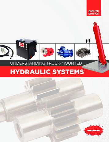
UNDERSTANDING TRUCK-MOUNTEDHYDRAULIC SYSTEMSThis booklet will attempt to answer questions and provide insights into howa truck-mounted, or mobile, hydraulic system operates, what componentsmake up the system, how they work, and why they sometimes fail to performas expected. Our frame of reference is that of a leading manufacturer anddistributor of hydraulic power systems and components. As such, theinformation gathered here represents the combined experience of manyknowledgeable professionals over many years.Our intent is to consider the entire system and its function as well as theindividual components. While the individual design may vary, the basicfunctions and terminology of all systems remain the same. The laws of physicsstill apply and most malfunctions are both predictable and preventable.While some systems may not be exposed to extreme temperatures or longduty cycles, generally speaking, truck-mounted systems operate underconditions more rigorous than stationary hydraulic systems. Integratinghydraulics with the capabilities and limitations of the truck engine, transmission,and power take-off is paramount. Remember also that truck-mountedhydraulic systems differ from industrial systems in another important way—they have a driver.Muncie Power CS Series PTO andPL1 Series gear pump mounted toan Allison automatic transmission.Because hydraulic components experience stress from high pressures, it isimportant that they be properly installed. It is important to use torque wrenchesproperly and to apply torque evenly to avoid uneven stresses and preventleaks.We have attempted to publish facts about how components work, how totroubleshoot when they don’t, and what causes some of the predicamentsyou must correct. If you still have questions about your equipment’sperformance, consult the manufacturer’s service manual for operatingcycle times, pressures, oil recommendations, etc., particularly beforereplacing components.To assist in determining system requirements and selecting propercomponents, a complete page of hydraulic and mechanical formulas hasbeen provided on page 38 of this booklet.Muncie Power Products provides two other resources: our website and ourM-Power Software. The website, munciepower.com, contains informationon Muncie Power’s complete product line, service and installation manuals,authorized distributor locations, and much more. It also serves as a launchingpoint for our web-based M-Power. Within M-Power you can make powertake-off and pump selections, perform hydraulic and mechanical calculations,view service parts drawings, and cross over competitor model numbers.Also, while visiting the Muncie Power’s website, be sure to look in the trainingarea for information on the product training classes and seminars offered aswell as information about the online training, M-Power Tech.Finally, Muncie Power makes available to you one other very importantresource—our people. Muncie Power’s customer service managers are readyto share their knowledge with you and are just a toll-free phone call away.Call 800-367-7867 (FOR-PTOS) for assistance in component selectionor refer to system troubleshooting on page 36 of this manual.2 Customer Service 800-367-7867
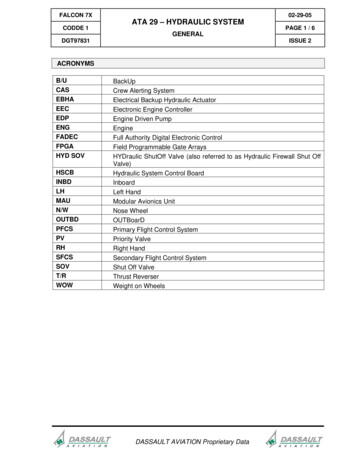
SECTION 1:PRINCIPLES OF HYDRAULICSTankTruck-mounted hydraulic systems, regardless of theirapplication, have in common the basic components andoperating principles of any hydraulic system. They utilizea power source, reservoir, pump, directionalPTOcontrol valve, and actuators to move andcontrol fluid in order to accomplish work.FilterPumpValveIn every hydraulic circuit, we start withmechanical power in the form of a rotatingshaft, convert it to hydraulic power with thepump, direct it with a valve to either a cylinder or a motor, andthen convert it back to mechanical power. We do this because, while inthe form of fluid power, we can direct and control the application of force.All hydraulic applications are based on flow and pressure requirements.Flow, expressed in gallons per minute (GPM), determines the speed at whicha hydraulic cylinder extends or a hydraulic motor turns. Flow is produced bythe pump. Pressure, expressed in pounds per square inch (PSI), determinesthe amount of force exerted. Pressure occurs when flow meets resistance.MotorCylinderA simple truck-mounted hydraulicsystem utilizing both a cylinder andhydraulic motor as actuators.Pressure is not produced, but is tolerated by the pump. The combination offlow and pressure required by a hydraulic system determine the operatinghorsepower (HP). This horsepower requirement is determined by the formula:Restriction applied to flowresults in pressure.HP GPM PSI 1,714Example: A hydraulic system requires 12GPM at an operating pressure of 2,000 PSI.The hydraulic horsepower requirement is:12 2,000 1,714 14 HPPascal’s LawThe basic principle governing hydraulics goes back to a seventeenthcentury French mathematician and philosopher, Blaise Pascal. Pascal’sLaw states that a pressure applied to a confined liquid is transmittedinstantly, equally, and undiminished, at right angles, to all surfaces ofthe container. Since oil is virtually non-compressible (only 0.5% per1,000 PSI) any force applied to one end of an oil-filled tube or hose willbe instantly transmitted to the other end.Both flow and pressureare required to accomplish work.It is important, from a troubleshooting standpoint, to remember thisdifferentiation between flow and pressure. Flow determines actuator speedand pressure determines system force. A hydraulic system that will notlift a load is likely experiencing a pressure related problem. One that willperform work, only slowly, is likely experiencing a flow related problem.NO FUNCTION no pressureSLOW FUNCTION low flowFOUR IMPORTANTHYDRAULIC LAWSI.PASCAL’S LAW: Apressure applied to aconfined fluid at rest istransmitted adiabatically(without gain or loss ofheat) with equal intensitythroughout the fluid and toall surfaces of the container.THESE LAWS WILL AFFECTBEHAVIOR OF AIR, WHICHCAUSES FAILURE. THEY HELPEXPLAIN THE PHENOMENA OFCAVITATION & AERATION.II. BOYLE’S LAW: Underconstant temperature, theabsolute pressure of a fixedmass of gas varies inverselywith its volume.III. CHARLES’ LAW: Underconstant pressure, thevolume of a fixed mass ofgas varies directly with theabsolute temperature.IV. HENRY-DALTON’S LAW:The amount of air that canbe dissolved in a system isdirectly proportional to theair pressure above the fluid.Understanding Truck-Mounted Hydraulic Systems munciepower.com 3
Four pressuresRemember, there are four pressures at work in a hydraulic system:ATMOSPHERICPRESSURE CHARTALTITUDEABOVESEALEVELIN FEETBAROMETER ATMOSPHERICREADING IN PRESSURE ININCHES OFPOUNDS PERMERCURYSQ. INCH(IN.HG)(BARS)029.9214.7 (1.01130)1,00028.814.2 (0.97344)2,00027.713.6 (0.93626)3,00026.713.1 (0.90246)4,00025.712.6 (0.86866)5,00024.712.1 (0.83486)6,00023.811.7 (0.80444)7,00022.911.2 (0.77402)8,00022.110.8 (0.74698)9,00021.210.4 (0.71656)10,00020.410.0 (0.68952)NOTE:1 in.Hg 0.4914 PSI1 PSI 2.035 in.HgAtmospheric pushes the oil from the reservoir to the pump inlet.Pumps are designed to be fed, not to draw oil. For this reason, it isdesirable to place the reservoir directly above the pump inlet. This isalso why we refer to the pump’s inlet port rather than its suction port.Atmospheric pressure at sea level is 14.7 PSI and approximately ½ PSIis lost with each 1,000 foot rise in elevation. In practical terms, it may benecessary to utilize larger diameter inlet hoses and pay closer attentionto reservoir placement in high altitude locations like Denver, Colorado,or Salt Lake City, Utah.Neutral system is the resistance to flow posed by the system itself asmeasured at the pump outlet when all control valves are in the neutralposition. Every component, hose, and fitting that the oil must flowthrough to get from the pump outlet to the return port of the reservoiradds to the neutral system pressure. This is sometimes referred to asΔP (Delta-P) or parasitic pressure. It takes away from the work than canbe performed by the actuator and transforms the wasted energy intosystem heat. Systems with high neutral pressure run hotter and wearout sooner. Ideally, neutral pressures should be kept under 300 PSI.In our troubleshooting experience, we have observed neutral systempressures as high as 900 PSI.Pump operating should be self-explanatory. This is the pressurerequired to accomplish work (to extend the cylinder or turn the hydraulicmotor) and is measured at the pump outlet. As measured at the pump,it is the actuator working pressure, in addition to the system pressuredrop. If 1,500 PSI is required to run a hydraulic motor and the systempressure drop is 500 PSI, the operating pressure measured at the pumpwill be 2,000 PSI.Relief pressure is the pressure at which the system relief valve willopen and bleed flow back to the reservoir until the system pressurediminishes. Typically, the relief pressure will be set approximately15% above the system working pressure. Thus, a system designed tooperate at 2,000 PSI would have its relief valve set for 2,300 PSI.HOW MUCH HYDRAULIC PRESSURE CAN BE EXPECTEDIN A TRUCK-MOUNTED HYDRAULIC SYSTEM?Force Pressure Area20,000 lbs.25 sq.in.800 PSI20,000 lbs.10 sq.in.2,000 PSIPressure is determined by area4 Customer Service 800-367-7867There are those who believe that system operating pressure isdetermined by a setting or an adjustment on a relief valve. Actually, aswe will see, hydraulic pressure is created or limited by several factors: load to be moved displacement of the hydraulic motor, or the area of thecylinder’s piston mechanical efficiency of the design hydraulic efficiency of the designWe will use the number 231 throughout our discussion of hydraulicsystem components. 231 is the number of cubic inches of liquid,for our purposes oil, contained in one gallon. Hydraulic componentmanufacturers rate pumps and motors according to their cubic inchdisplacement (CID). Just as we discuss auto engines in terms of cubicinches, we also specify and compare hydraulic pumps in terms of CID.In pump displacement terms, we are referring to the amount of oil flow apump produces with each complete rotation of its input shaft. Thus, a 4cu.in. pump will, with each shaft rotation, move 4 cu.in. of oil from its inlet
to its outlet. What does this mean in terms of GPM, the measurementwe are most accustomed to? If our application requires a flow rate of20 GPM we must turn the input shaft of our 4 cu.in. pump at a speed of1,155 revolutions per minute (RPM).20 GPM 231 4,620 (cu.in. in 20 gal.)4,620 4 cu.in. (pump displacement) 1,155 RPMWe will also use the number 231 in our discussion of hydraulicreservoirs, cylinders, and motors.Hydraulic system efficiencyNo hydraulic system is 100% efficient. This is because no individualhydraulic component is 100% efficient. There are two mechanicalobstacles that must be overcome: friction and internal leakage. Both,which are unavoidable, take away from the overall efficiency of thecomponents and, therefore, the entire system.It has been calculated that hydraulic systems that utilize cylinders astheir actuators, when new, are approximately 85% efficient, whereashydraulic motor systems are approximately 80% efficient. This has twoeffects: One, pump input horsepower requirements will exceed outputhorsepower by a factor equal to the inefficiency. Two, the horsepowerlost through inefficiency will be converted to heat.Volumetric efficiencyThe actual output flow of a pump ascompared to it’s theoretical outputbased on cubic inch displacement.VE Actual output Theoretical outputMechanical efficiencyA measure of a pump’s internalpower losses as a percentage of theinput power. (Any internal friction—bearings, seals, etc.—will resultin a power loss.)Overall efficiencyThe efficiency of the pump whenthe volumetric and mechanicalefficiencies are factored.Gear pumps, for example, when new, have a volumetric efficiency ofapproximately 94%. This means that for every 10 gallons of oil that isdrawn in through the inlet port, 9.4 gallons will exit through the outlet.The remaining .6 gallons, more or less, will slip past the tips of thegear teeth. What happens when components leak internally—heat.Inefficiency manifests itself as heat. The greater the system inefficiency,the higher the heat. As time passes, the components wear and becomeless efficient, hydraulic systems operate slower and generate more heat.Open and closed center hydraulic systemsAs we have discussed, to perform work hydraulically requires thepresence of two conditions: flow and pressure. If either is eliminated,work stops. Alternately, if either can be controlled, we can controlhydraulic work. This has lead to two designs of hydraulic systems:open center and closed center.Open centerOpen CenterThe term open center describes both the type of hydraulic circuit and,literally, the construction of the directional control valve. In an open centersystem, flow is continuous and pressure is intermittent. With the pumpturning, flow is produced and is routed through a central passageway inthe directional control valve back to tank. When a spool in the directionalcontrol valve is stroked, flow is directed toward a load resulting inpressure. Once the pressure exceeds the load, the load moves.Closed centerLikewise, the term closed center describes both the type of hydrauliccircuit and the construction of the directional control valve. In a closedcenter system, flow is intermittent and pressure is continuous.With the pump turning, only enough flow is produced to maintain astandby pressure at the directional control valve and to keep the pumplubricated. When a spool is stroked, a pathway for flow is revealed and,simultaneously, pressure signal information is delivered to the pumpfrom the directional control valve, signaling the pump to produce flow.Closed CenterUnderstanding Truck-Mounted Hydraulic Systems munciepower.com 5
SECTION 2:THE PRIME MOVERTG SeriesThe prime mover supplies the mechanical power to drive the hydraulic system.In the mobile hydraulics industry, the prime mover we are most familiar with isthe truck engine. The truck engine is frequently used to provide power througha power take-off (PTO), through belts from the crankshaft pulley, or directlythrough a tubular driveshaft assembly. On some high horsepower systems anauxiliary, or pony engine, might be used. In any case, the prime mover must becapable of providing the horsepower necessary to power the hydraulic system.Refer to the hydraulic horsepower formula on page 3.Power take-offsThe original PTOs were single gear models with a gear that slid into and meshwith a transmission gear, resulting in output shaft rotation. Single gear PTOsare limited by their speed and horsepower capabilities. You will find themused primarily on small, single axle dump trucks and agricultural hoists. Mostsingle gear PTO’s have become obsolete. MC1 SeriesDouble or triple gear, PTOs, found on dump trucks, refuse vehicles,wreckers, aerial bucket trucks, tank trucks, and truck-mounted cranes, are themost widely used type of PTO because of their versatility. These types of PTOscan be engaged by cable, air, electric solenoid, or mechanical levers. They offera wide variety of output shafts and mounting flanges, which allow for directcoupling of hydraulic pumps from major manufacturers. PTO output shaftspeeds can be faster or slower by changing the internal gear ratio of the PTO.The newest design in PTOs is the clutch shift type. These models engageby means of friction disks rather than sliding gears. Clutch type PTOs arecommonly used on refuse, utility, and emergency equipment—garbage trucks,aerial bucket trucks, and fire/rescue vehicles.FR6Q Serieswith theMuncie Start We will not attempt to go into PTO selection in this text. Suffice to say thatwhen a PTO is utilized as the source of power for the hydraulic system, it mustmeet the torque, horsepower, and speed requirements of the system. For moredetailed information on PTO types, selection, and troubleshooting see ourtraining guide on “Understanding Power Take-off Systems.”Engine crankshaft driven82 SeriesPTOs are usedto transfer engine powerto a hydraulic pump.Many refuse and snow control vehiclesutilize a front-mounted hydraulic pumpdriven by a tubular driveshaft assemblyfrom the harmonic balancer of the engine.This live power arrangement has theadvantage of providing full engine torqueon high-demand applications while eliminatingthe cost of the PTO. The disadvantage to thistype of installation is in the requirement to raise,or core, the radiator to allow passage for thedriveshaft; extend the front frame rails; andfabricate a mounting bracket for the pump.Crankshaftdriven clutch pumpMaximum U-Joint Operating AngleAO Shaft Length56 Customer Service 800-367-7867
Drivelines used for this application must be of the balanced, tubular typecapable of transmitting high torque loads. The Spicer 1310 series or itsequivalent is commonly specified. Solid bar stock should never be used incrankshaft drive applications.Another important consideration is driveshaft angularity. Not only is itnecessary to keep the angle shallow—generally less than 7 F—but alsoto keep the pump input shaft parallel to the engine crankshaft within 1½ .Likewise, the yokes on each end of the shaft must be in phase, or alignedwith each other. Failure to address any of these requirements will result indriveshaft vibration and damage to the pump.Auxiliary enginesAuxiliary engines, gasoline or diesel, are typically used only in applicationsrequiring full engine horsepower and torque. In truck-mounted applicationsthis would include such things as large vacuum pumps and concretepumps. Usually, one or more hydraulic pumps are coupled to theengine’s output shaft.Belt-driven pumpsBelt-driven pumps, or “clutch pumps,” are popular power sources forapplications such as wreckers and bucket trucks. They also represent analternative to a PTO system on vehicles without PTO apertures or whereaccess to the transmission PTO aperture is obstructed. The clutch pumpis belt-driven from the crankshaft pulley through an electric clutch similarto that found on an automobile air conditioner compressor.One important consideration in clutch pump applications is thehorsepower limitation of the engine belts. Dual ½ inch, automotive typebelts can transmit about 7 HP. Most applications will utilize two v-beltsor a poly-v type belt to drive the pump. This belt limitation (andavailable space limitations) prohibits the use of largedisplacement pumps (greater than 2½ cu.in.)in clutch pump applications. Serpentine beltdrives can deliver horsepower comparableto that of two v-belts.DRIVELINE ANGLESABMAXMAXSPEED ANGLE(RPM) TJA “A”3,5003,0002,5002,0001,5001,000PUMPTOP VIEWBPTOTRANSMISSION5 6 PUMP7 TJA A2 B28 11 True Joint Angle (TJA)12 For speeds over 2,500 RPM, contactMuncie Power for approval.For installation with angels in the topand side views, use this formula tocompute the true joint angle (TJA).Note: Solid shafting is notrecommended for continuousoperating speeds above 1,000 RPM.Changes in truck design and crampedengine compartments present challengesto clutch pump manufacturers. However,clutch pumps remain a popular option forhydraulic applications requiring flows ofup to 15 GPM.Belt-driven Clutch PumpClutch Pump and Bracket KitProper belt alignment and tension are critical to clutch pump performance.Understanding Truck-Mounted Hydraulic Systems munciepower.com 7
PUMPS PRODUCE FLOW PUMPS DO NOT PRODUCEPRESSURE PRESSURE RESULTS WHENFLOW MEETS RESISTANCESECTION 3:PUMPSHydraulic pumps take the mechanical energy of the prime mover (aturning force) and convert it to fluid energy in the form of oil flow. Aspreviously discussed, we normally refer to this oil flow in terms of gallonsper minute (GPM). It is this flow rate which determines the speed atwhich a system will operate.If you have the manufacturer’s specifications for the hydraulic system,they should state the operating flow (GPM/LPM) and pressure (PSI/BAR)requirements. There may also be a suggested make and model for thepump. As far as the hydraulic system is concerned, any pump whichwill meet the flow and pressure requirements will work equally well.Some may be more efficient. Some may look different. The real costmay not be in the purchase price but in the cost of operating andmaintaining the system over its life.Pumps may be of either a uni-rotational or bi-rotational design.Uni-rotational pumps are designed to operate in only one directionof shaft rotation, while bi-rotational pumps can operate in either direction.Uni-rotational pumps are distinguishable in that the inlet and outlet portsare different sizes, with the inlet being the larger. Some bi-rotational pumpshave two input shafts to match the rotation of the driveshaft. Bi-rotationalpumps also tend to have equally sized ports since either can be the inletor outlet, depending on rotation.NOTE: As a rule of thumb, if the pump is PTO driven by a PTO on amanual transmission, the input rotation will be left-hand (CCW). If PTOdriven on an automatic transmission it will be right-hand (CW) rotation.Ford automatics are the exception. Front-mounted, crankshaft drivenpumps will be left-hand rotation.Positive and variable displacement pumpsThree types of hydraulic pump construction are typically found in mobilehydraulic applications: gear, piston, and vane.Gear pumpsGear pumps are the most common design in usefor truck-mounted hydraulic systems. Gear pumpsare relatively inexpensive, have few moving parts,are easy to service, and are generally more tolerantof contamination than other designs.PK1 Series PumpGear pumps are fixed, or positive, displacement pumps. That is, theyproduce the same volume of flow with each complete shaft rotation. Thetypes of systems in which gear pumps are generally used are referred toas open center systems. Open center systems are those which allow oilto flow through the open center core of the directional valve and back toreservoir under low, return pressure when it is not being directed to a workfunction. Gear pumps can only be used in closed center systems if specialunloading valving is utilized.Gear Pump Cross Section8 Customer Service 800-367-7867Gear pumps operate by trapping oil in the areas between the teethof their two gears and the body of the pump, transporting it around thecircumference of the gear cavity, and forcing it through the outlet portas the gears mesh. A small amount of pressurized oil is allowed behindbrass alloy thrust plates, often referred to as wear plates, at each endof the gear set, pushing them tightly against the gear ends to improvepump efficiency.Gear pumps are rated in terms of their CID, maximum pressure rating, andmaximum input speed limitation.
Muncie Power gear pumps are available in displacements from ½ cu.in.to 14 cu.in. Pump manufacturers use a rating speed to describe theirpumps. This allows them to describe their pump in GPM terms most usersare accustomed to. A manufacturer using 1,000 RPM as his rating speedwould, for example, refer to their 7 cu.in. pump as a 30 GPM pump(7 cu.in. 1,000 231 30.3 GPM). A manufacturer using 1,200 RPMas their rating speed would refer to the same 7 cu.in. pump as a 36 GPMpump (7 cu.in. 1,200 231 36.36 GPM).PUMP OUTPUT FLOWBASED ON CID THEORETICAL1.2001,5002,0002,5001456911 13Caution: Not all pump manufacturers use the same rating speed. Someuse 1,000 RPM, some use 1,200, and some use 1,800. Care must be takenin comparing or replacing pumps from different manufacturers. You do notwant to sell a pump too large or small for their application because you did notmake an accurate comparison. If possible, make your determination based onCID comparisons or the original equipment specification.2910 13 17 22 26313 16 19 26 32 39417 21 26 36 43 52522 26 32 43 54 65626 31 39 52 65 78All pumps, regardless of design, have a maximum pressure rating. Thisis the highest pressure at which the pump was designed to operate. It isnot the pressure that the pump encounters every time it is operating. Themaximum operating pressure rating is affected by many variables includingshaft diameter, bearing loads, body composition, port type, and port size.One major factor that affects pressure ratings of gear pumps is the distancebetween the front and rear bearings that support the pump’s gears. Thegreater the unsupported length, the lower the maximum pressure rating.730 36 45 61 76 91835 42 52 69 87 104939 47 58 78 97 117Formula: GPM CID RPM 231A pump's maximum operating speed is based primarily on the limit atwhich the rotating gears can fill the gear cavity before cavitation begins,although bearing type and the quality of the hydraulic oil can also be factors.Oftentimes, this relates to port diameter and location. It can also be affectedby hose size, reservoir location, and oil viscosity. Operating at excessivespeeds can result in cavitation and or heat damage. More on cavitation later.SAEMOUNTING/SHAFT SIZESSAEPILOTA3.25"Interestingly, gear pumps also have a minimum speed limitation. Geartype pumps are generally most efficient in the upper third of their operatingspeed range. Pumps turned slowly are less efficient than those turned faster.Operating below the minimum RPM results in excess heat generation, whichcan damage seals and wear plates. Generally speaking, gear pumps shouldnot be operated at input shaft speeds under 1,000 RPM. The chart belowshows a typical performance chart for a gear pump. Notice that at a constantpressure the pump’s volumetric efficiency will increase as pump shaftBOLTspeed increases. You will also notice that at a constant speed efficiencywillCIRCLESdecrease as pressure increases. Changes in either speed or pressure willaffect a gear pump’s volumetric efficiency. Pumps operated in the upperend of their speed range are more efficient than those operated in thelower end. Keep this in mind when selecting a PTO.PUMP PERFORMANCE CHART3,0001,000SHAFT SPEED (RPM)DISPLACEMENTBBBCBOLT CIRCLE SHAFT SIZE4"(2) 4.188".624"(2) 5.75".875" - 13 spl.4"(2) 5.75"1" - 15 spl.5"(2) 6.75"4"(4) 5".875" - 13 spl.(4) 5"1" - 14 spl.1.25" - 14 spl.(4) 6"1.25" - 14 spl.PILOTBCMODEL: PK1-13 (2.96 cu.in. Displacement TEST: Average pump test data TEMP: 120 F VISCOSITY: 100 1
drop. If 1,500 PSI is required to run a hydraulic motor and the system pressure drop is 500 PSI, the operating pressure measured at the pump will be 2,000 PSI. Relief pressure is the pressure at which the system relief valve will open and bleed flow back to the reservo


![Bosch ESI[truck] Heavy Duty Truck Software Update – Q2 .](/img/22/bosch-esitruck-heavy-duty-truck-release-notes-details-2019-2-0-0-0.jpg)