Transcription
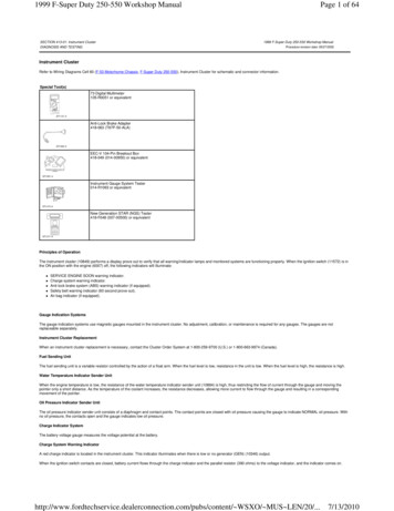
1999 F-Super Duty 250-550 Workshop ManualSECTION 413-01: Instrument ClusterDIAGNOSIS AND TESTINGPage 1 of 641999 F-Super Duty 250-550 Workshop ManualProcedure revision date: 09/27/2002Instrument ClusterRefer to Wiring Diagrams Cell 60 (F-53 Motorhome Chassis, F-Super Duty 250-550), Instrument Cluster for schematic and connector information.Special Tool(s)73 Digital Multimeter105-R0051 or equivalentAnti-Lock Brake Adapter418-063 (T97P-50-ALA)EEC-V 104-Pin Breakout Box418-049 (014-00950) or equivalentInstrument Gauge System Tester014-R1063 or equivalentNew Generation STAR (NGS) Tester418-F048 (007-00500) or equivalentPrinciples of OperationThe instrument cluster (10849) performs a display prove out to verify that all warning/indicator lamps and monitored systems are functioning properly. When the ignition switch (11572) is inthe ON position with the engine (6007) off, the following indicators will illuminate: SERVICE ENGINE SOON warning indicator.Charge system warning indicator.Anti-lock brake system (ABS) warning indicator (if equipped).Safety belt warning indicator (60 second prove out).Air bag indicator (if equipped).Gauge Indication SystemsThe gauge indication systems use magnetic gauges mounted in the instrument cluster. No adjustment, calibration, or maintenance is required for any gauges. The gauges are notreplaceable separately.Instrument Cluster ReplacementWhen an instrument cluster replacement is necessary, contact the Cluster Order System at 1-800-259-9700 (U.S.) or 1-800-663-9974 (Canada).Fuel Sending UnitThe fuel sending unit is a variable resistor controlled by the action of a float arm. When the fuel level is low, resistance in the unit is low. When the fuel level is high, the resistance is high.Water Temperature Indicator Sender UnitWhen the engine temperature is low, the resistance of the water temperature indicator sender unit (10884) is high, thus restricting the flow of current through the gauge and moving thepointer only a short distance. As the temperature of the coolant increases, the resistance decreases, allowing more current to flow through the gauge and resulting in a correspondingmovement of the pointer.Oil Pressure Indicator Sender UnitThe oil pressure indicator sender unit consists of a diaphragm and contact points. The contact points are closed with oil pressure causing the gauge to indicate NORMAL oil pressure. Withno oil pressure, the contacts open and the gauge indicates low oil pressure.Charge Indicator SystemThe battery voltage gauge measures the voltage potential at the battery.Charge System Warning IndicatorA red charge indicator is located in the instrument cluster. This indicator illuminates when there is low or no generator (GEN) (10346) output.When the ignition switch contacts are closed, battery current flows through the charge indicator and the parallel resistor (390 ohms) to the voltage indicator, and the indicator comes /pubs/content/ WSXO/ MUS LEN/20/.7/13/2010
1999 F-Super Duty 250-550 Workshop ManualPage 2 of 64When the generator builds up enough voltage to energize a circuit in the voltage regulator, the indicator goes out.Vehicle Speed Sensor (VSS)The VSS has been deleted for 1999. On vehicles equipped with 4-wheel anti-lock brake systems (4WABS), the vehicle speed signal is generated by the rear anti-lock brake sensor and sentto the 4WABS module. The 4WABS module sends the vehicle speed signal via circuit 679 (GY/BK) to all systems that require a vehicle speed signal input. Vehicles equipped with rear antilock brakes (RABS) generate a vehicle speed signal from the rear axle speed sensor. The generic electronic module (GEM) receives this signal (VSS GEM) for internal use and thendistributes it to the appropriate other users (i.e., the powertrain control module [PCM], speed control module, and speedometer).SpeedometerThe electronic speedometer (17255) receives a speed signal from the 4WABS module (if equipped with 4WABS) or the GEM/CTM (if equipped with RABS).OdometerA million-mile tamper-resistant odometer is standard. Replacement speedometers have a resettable odometer.NOTE: Some state laws require that the odometer in any replacement speedometer must register the same as on the removed odometer. Replacement speedometers and odometermodules with the mileage preset are available through Ford electronic repair centers.If the actual vehicle mileage cannot be determined, the repair centers are able to supply odometers set to "0" miles. An odometer mileage sticker is supplied with the replacement odometer.This sticker must display the estimated vehicle mileage and be affixed to the driver door jamb.Trip OdometerThe trip odometer indicates how many miles the vehicle has been driven since the last reset.TachometerThe tachometer (17360) is a 6000-rpm tachometer that is hardwired to the PCM through circuit 648 (WH/PK).Warning IndicatorsBrake SystemNOTE: On late production vehicles, the BRAKE warning indicator is located in the lower RH corner of the instrument cluster.All vehicles use a brake system warning indicator in the instrument panel to warn of system malfunctions. The red brake warning light (BRAKE) is used to indicate a low fluid level, brakemalfunction, or a parking brake that is not fully released. The brake fluid level switch is located in the brake fluid reservoir.The yellow brake warning indicator is used to indicate a malfunction or deactivation of the anti-lock brake system (ABS). It illuminates when triggered by the ABS control module and staysilluminated as long as the malfunction remains in the system.Service Engine Soon Warning IndicatorThe SERVICE ENGINE SOON warning indicator is illuminated when a diagnostic trouble code (DTC) is sensed in the closed loop by the powertrain control module (PCM) (12A650).Air BagIf an air bag system DTC is detected, the air bag indicator is illuminated (if equipped with an air bag).Safety BeltThe safety belt warning indicator is powered through the generic electronic module (GEM). When the ignition key is turned on, the indicator illuminates for four to eight seconds even if thesafety belt is buckled.Low FuelWhen the fuel level drops to a predetermined level, the low fuel warning indicator will illuminate.Door AjarThe DOOR AJAR indicator illuminates when any of the vehicle doors are open.High BeamThis indicator is illuminated when the high beams are on.Speed ControlNOTE: This indicator is available on late production vehicles equipped with speed control.The speed control indicator (CRUISE) will illuminate when the speed control is engaged.Fuel ResetThe FUEL RESET indicator is grounded through the inertia switch whenever the vehicle is subjected to a high force situation. The inertia fuel shutoff switch (IFS switch) (9341) cuts off thefuel pump motor.The fuel cutoff system is a safety feature in the event of an accident. The FUEL RESET indicator will illuminate, indicating that the inertia fuel shutoff switch must be reset before the vehiclecan be operated.Water in Fuel (Diesel Only)The WATER IN FUEL indicator will illuminate when 100cc (0.2 pints) of water has accumulated in the fuel filter/water separator. The WATER IN FUEL indicator will prove out when theignition switch is in the START position. Refer to the owner literature for draining procedures.Wait to Start (Diesel Only)The WAIT TO START indicator will illuminate when the ignition switch is in the ON position with the engine OFF while the glow plugs are n.com/pubs/content/ WSXO/ MUS LEN/20/.7/13/2010
1999 F-Super Duty 250-550 Workshop ManualPage 3 of 64Warning Indicators — Engine Oil Pressure, Engine Coolant Temperature, Low FuelThe engine oil pressure warning indicator will illuminate if the engine oil pressure drops below approximately 42 kPa (6 psi).The engine coolant temperature warning indicator will illuminate if the engine temperature exceeds approximately 121 C (250 F).The low fuel warning indicator will illuminate if the fuel level drops below approximately 4-8L (1-2 gal).Inspection and Verification1. Verify the customer concern by operating the system in question.2. Visually inspect the components listed in the following chart:Visual Inspection ChartMechanical Damaged engine oil filterDamaged oil pumpLow engine oil levelStuck oil pressure gauge needleStuck coolant temperature gaugeDoor adjustmentTripped inertia fuel shutoff (IFS) switchEngine coolant levelDamaged water thermostatElectrical Blown fuse(s)Damaged miniature bulb(s)Damaged wiring harnessLoose or corroded connectorsDamaged instrument cluster3. Verify the following systems are working properly: Charging.Fuel.Cooling.Safety belt warning chime (GEM).Turn signals.Headlamps.Anti-theft.Vehicle speed control (if equipped).If the system(s) is not working properly, refer to the appropriate section of the workshop manual.4. If the concern remains after the inspection, connect the New Generation STAR (NGS) Tester to the data link connector (DLC) located beneath the instrument panel and select thevehicle to be tested from the NGS menu. If the NGS does not communicate with the vehicle: check that the program card is properly installed. check the connections to the vehicle. check the ignition switch position.5. If the NGS still does not communicate with the vehicle, refer to the New Generation STAR Tester manual.6. Perform the DATA LINK DIAGNOSTIC TEST. If the NGS Tester responds with: CKT914, CKT915 or CKT70 ALL ECUS NO RESP/NOT EQUIP, refer to Section 418-00. NO RESP/NOT EQUIP for generic electronic module (GEM), go to Pinpoint Test A or for the anti-lock brake system (ABS) module, refer to Section 206-09A (RABS) or Section206-09B (4WABS). NOTE: For vehicles built prior to February 5, 1998, the following criteria must be met when performing the GEM On-Demand Self-Test: headlamps and parklamps must be offand the power windows must be completely up. Failure to meet this criteria will result in DTCs B1577 and B2357 being set. For vehicles built after February 5, 1998, thefollowing criteria must be met when performing the GEM On-Demand Self-Test: headlamps and parklamps must be on. Failure to meet this criteria will result in DTC B1575being set.SYSTEM PASSED, retrieve and record the continuous diagnostic trouble codes (DTCs), erase the continuous DTCs and perform self-test diagnostics for the GEM.7. If the DTCs retrieved are related to the concern, go to the GEM Diagnostic Trouble Code (DTC) Index to continue diagnostics.8. If no DTCs related to the concern are retrieved, proceed to Symptom Chart to continue diagnostics.GEM Diagnostic Trouble Code (DTC) IndexGEM Diagnostic Trouble Code (DTC) IndexDTCCausedByActionB1217 Horn Relay Coil Circuit FailureGEMREFER to Section 501-14B.B1218 Horn Relay Coil Circuit Short to BatteryGEMREFER to Section 501-14B.B1243 Express Window Down Switch Circuit Shortto BatteryGEMREFER to Section 501-11.B1300 Power Door Lock Circuit FailureGEMREFER to Section 501-14B.B1302 Accessory Delay Relay Coil Circuit FailureGEMREFER to Section 501-11.B1304 Accessory Delay Relay Coil Circuit Short toBatteryGEMREFER to Section 501-11.B1310 Power Door Unlock Circuit FailureGEMREFER to Section 501-14B.B1317 Battery Voltage HighGEMREFER to Section 414-00.B1318 Battery Voltage LowGEMREFER to Section 414-00.B1322 Driver Door Ajar Circuit Short to GroundGEMREFER to Section alerconnection.com/pubs/content/ WSXO/ MUS LEN/20/.7/13/2010
1999 F-Super Duty 250-550 Workshop ManualPage 4 of 64B1323 Door Ajar Lamp Circuit FailureGEMB1325 Door Ajar Lamp Circuit Short to BatteryGEMGO to Pinpoint Test V.GO to Pinpoint Test V.B1330 Passenger Door Ajar Circuit Short toGroundGEMREFER to Section 417-02.B1338 Door Ajar RR Circuit Short to GroundGEMREFER to Section 417-02.B1340 Chime Input Request Circuit Short toGroundGEMREFER to Section 413-09.B1342 ECU is Defective, RAM/ROM ChecksumFailureGEMCLEAR the DTCs. RETRIEVE the DTCs. If DTC B1342 is retrieved, REPLACE the GEM. REFER to Section 419-10.TEST the system for normal operation.B1352 Ignition Key-In Circuit FailureGEMREFER to Section 413-09.B1355 Ignition Run Circuit FailureGEMREFER to Section 211-05.B1359 Ignition Run/ACC Circuit FailureGEMREFER to Section 211-05.B1366 Ignition Start Circuit Short to GroundGEMREFER to Section 211-05.B1371 Illuminated Entry Relay Circuit FailureGEMREFER to Section 417-02.B1373 Illuminated Entry Relay Short to BatteryGEMREFER to Section 417-02.B1396 Power Door Lock Circuit Short to BatteryGEMREFER to Section 501-14B.B1397 Power Door Unlock Circuit Short to BatteryGEMREFER to Section 501-14B.B1398 Driver Power Window One Touch WindowRelay Circuit FailureGEMREFER to Section 501-11.B1400 Driver Power Window One Touch RelayCircuit Short to BatteryGEMREFER to Section 501-11.B1405 Driver Power Window Down Circuit Short toBatteryGEMREFER to Section 501-11.B1410 Driver Power Window Motor Circuit FailureGEMREFER to Section 501-11.B1426 Lamp Seat Belt Circuit Short to BatteryGEMGO to Pinpoint Test W.B1428 Lamp Seat Belt Circuit FailureGEMGO to Pinpoint Test W.B1431 Wiper Brake/Run Relay Circuit FailureGEMREFER to Section 501-16.B1432 Wiper Brake/Run Relay Circuit Short toBatteryGEMREFER to Section 501-16.B1434 Wiper Hi/Low Speed Relay Coil CircuitFailureGEMREFER to Section 501-16.B1436 Wiper Hi/Low Speed Relay Coil CircuitShort to BatteryGEMREFER to Section 501-16.B1438 Wiper Mode Select Switch Circuit FailureGEMREFER to Section 501-16.B1441 Wiper Mode Select Switch Circuit Short toGroundGEMREFER to Section 501-16.B1446 Wiper Park Sense Circuit FailureGEMREFER to Section 501-16.B1450 Wiper Wash/Delay Switch Circuit FailureGEMREFER to Section 501-16.B1453 Wiper Wash/Delay Switch Circuit Short toGroundGEMREFER to Section 501-16.B1458 Wiper Washer Pump Motor Relay CircuitFailureGEMREFER to Section 501-16.B1460 Wiper Washer Pump Motor Relay CoilCircuit Short to
13.07.2010 · Instrument Cluster Refer to Wiring Diagrams Cell 60 ( F-53 Motorhome Chassis , F-Super Duty 250 -550 ), Instrument Cluster for schematic and connector information. Principles of Operation The instrument cluster (10849) performs a display prove out to verify that all warning/indicator lamps and monitored systems are functioning properly. When the ignition switch (11572) is in the ON position .