Transcription
Metallurgical Aspects of Fatigue Failure of Steel-Part IMetallurgical Aspects of Fatigue Failure of Steel-Part IMetallurgical Aspects of Fatigue Failure of Steel-Part IDr. Ahmed SharifDepartment of Materials and Metallurgical EngineeringBangladesh University of Engineering and TechnologyMetallurgical Aspects of Fatigue Failure ofSteel-Part IDr. Ahmed SharifDepartment of Materials and Metallurgical EngineeringBangladesh University of Engineering and TechnologyBiographyDr. Ahmed Sharif received his first class honours B.Sc. Engineering degree in Metallurgical Engineering from the Bangladesh University of Engineering and Technology (BUET), Dhaka in 1998 and also the M. Sc. Engineering degree in 2001.He began his academic career with the same department as a Lecturer from 1999 and was promoted to Associate Professor in 2010. He completed his Ph. D. in 2005 from City University of Hong Kong (CityU). His electronic packaging materialsresearch, has led to the award of an international prize the “IEEE CPMT Young Scientist Award” from IEEE Japan chapterin 2004. His publication record, 40 peer-reviewed (SCI listed) journal papers with h-index of 17 reflects his potentiality andleadership qualities in research.ABSTRACTMetals when subjected to repeated cyclic loadexhibit damage by fatigue. The magnitude of stress in each cycle is notsufficient to cause failure with a single cycle. Large numbers of cycles are therefore needed for failure by fatigue. Importantly, fatigue crack nucleates and grows at stress levels far below the monotonic tensile strength of the metal. The crackadvances continuously by very small amounts, its growth rate decided by the magnitude of load and geometry of the component. There has been much research into fatigue of steel. In this context, at first the major microstructures and the phasetransformations by which these microstructures in carbon and low-alloy steels are developed are described briefly. Lateron, some knowledge of basic aspects of the fatigue mechanism is described with particular emphasis on the developmentsin fatigue life prediction methods.1.1 Introduction to SteelThe term steel is used for many different alloys of iron. These alloys vary both in the way they are made and in theproportions of the materials added to the iron. All steels, however, contain small amounts of carbon and manganese. Inother words, it can be said that steel is a crystalline alloy of iron, carbon and several other elements, which hardens aboveits critical temperature. Steel, by definition, must be at least 50% Fe and must contain one or more alloying element. Thesealloying elements include carbon, manganese, silicon, nickel, chromium, molybdenum, phosphorus, copper, vanadium,titanium, niobium, boron, and aluminum. Carbon steels, generally called plain carbon steels, range in carbon content fromapproximately 0.10% C to over 1% C.1.2 Classification of SteelsSteels can be classified by a variety of different systems depending on:32 BSRM Seminar on Fatigue Properties of Constructional Steel The composition, such as carbon, low-alloy, or stainless steels The manufacturing methods, such as open hearth, basic oxygen process, or electric furnace methods The finishing method, such as hot rolling or cold rolling The product form, such as bar, plate, sheet, strip, tubing, or structural shape The deoxidation practice, such as killed, semikilled, capped, or rimmed steel The microstructure, such as ferritic, pearlitic, and martensitic The heat treatment, such as annealing, quenching and tempering, and thermomechanical processingBSRM Seminar on Fatigue Properties of Constructional Steel 33
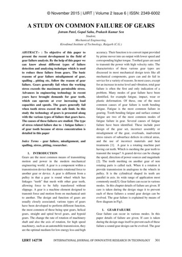
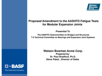
Metallurgical Aspects of Fatigue Failure of Steel-Part IMetallurgical Aspects of Fatigue Failure of Steel-Part I(a)(c)(b)Fig.2 For the body centered cubic crystal structure, (a) a hard sphere unit cell representation,(b) a reduced-sphere unit cell, and (c) photomicrograph of ferrite.The solid solution formed when carbon atoms are absorbed into the face-centred cubic structure of iron is called Austeniteandthe extremely low level of solid solution formed when carbon dissolves in body-centred cubic iron is called Ferrite. For manypractical purposes we can regard ferrite as having the same properties as pure iron. The symbol γ(‘gamma’) is used todenote both the face-centred cubic form of iron and the solid solution austenite, whilst the symbol (‘alpha’) is used to denoteboth the body-centred cubic form of iron existing below 910 C and the solid-solution ferrite.(a)(c)(b)Fig. 3 For the facecentered cubic crystal structure,(a) a hard sphere unit cell representation, (b) a reduced-sphere unit cell, and (c) photomicrograph of austeniteWhen carbon is precipitated from austenite it is not in the form of elemental carbon (graphite), but as the compound iron carbide,Fe3C, usually called Cementite(Fig. 4). This substance, like most other metallic carbides, is very hard, so that, as the amountof carbon (and hence, of cementite) increases, the hardness of the slowly cooled steel will also increase.Fig. 1 Classification of steels. Source: D.M. Stefanescu, University of Alabama,TuscaloosaOf the aforementionedclassification systems, chemical composition is the most widely usedinternationally and will be emphasized in this article.(a)(b)1.3 The EquilibriumDiagramA phase diagram is a graphical representation of the microstructural changes in relation to composition, and temperature inan alloy system. For steel, the system is called as the iron-carbon diagram.By reference to the diagram, structural or physicalcondition can be found exactly at any given temperature for steel of any composition in the series. We can also in manycases forecast with a fair degree of accuracy the effect of a particular heat-treatment on the alloy. These are two of themore important uses of the thermal-equilibrium diagram as a metallurgical tool. Plain carbon steels are generally definedas being those alloys of iron and carbon which contain up to 2.0% carbon.Iron, at temperatures below 910 C, has a body-centred cubic structure (Fig. 2), and above this temperature the structurewill change to facecentred cubic (Fig. 3). On cooling, the change is reversed and a body-centred cubic structure is oncemore formed. The importance of this reversible transformation lies in the fact that up to 2.0% carbon can dissolve inface-centred cubic iron, forming what is known as a ‘solid solution’, whilst in body-centred cubic iron no more than 0.02%carbon can dissolve in this way.As a piece of steel in its face-centred cubic form cools slowly and changes to its bodycentredcubic form, any dissolved carbon present in excess of 0.02% will be precipitated, whilst if it is cooled rapidly enough suchprecipitation is prevented.34 BSRM Seminar on Fatigue Properties of Constructional SteelFig.4 (a) Crystal structure of cementite (green and red spheres represent Fe and C atoms, respectively) and(b) spheroidite microstructures of steel. The light regions are ferrite while the dark are cementite.BSRM Seminar on Fatigue Properties of Constructional Steel 35
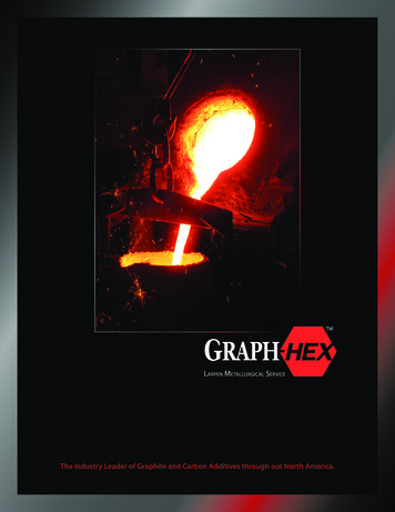
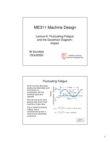
Metallurgical Aspects of Fatigue Failure of Steel-Part IMetallurgical Aspects of Fatigue Failure of Steel-Part IPearliteis another common constituent in plain carbon and low-alloy steels and consists of two phases: ferrite andcementite. The ferrite and cementite phases form a platelike lamellar morphology. The pearlite appears dark in thesemicrostructures, because the etchant attacked the ferrite phase in the pearlite, leaving the cementite phase untouched.Many colonies of pearlite are shown in this micrograph (Fig. 5). A colony represents a single orientation of the pearlitelamella. In these heavily etched specimens, the cementite plates are evident, because the ferrite between the plates hasbeen dissolved by the etching solution.(c)(b)(a)Martensiteis a constituent that is formed by rapid cooling (quenching) plain carbon or low-alloy steels from thehigh-temperature austenite phase (Fig. 7). Carbon is dissolved in the ferrite well past its room-temperature solubility limitof 0.005% C, and thus, the constituent is no longer considered ferrite. Because of the supersaturated carbon, martensiteis a very hard constituent. To be useful, martensite is usually tempered (heated to a temperature between approximately420 and 650 C, or 800 and 1200 F) to allow some of the carbon to precipitate out as a carbide phase, usually cementite.Fig. 5 (a) Schematic representation of the formation of pearlite from austenite;direction of carbon diffusion indicated by arrows and(b) Microstructure of pearlite colonies in plain carbon UNS G10800 steeltaken in the scanning electron microscope.Bainiteis also a constituent that consists of two phases: ferrite and cementite. The appearance of bainite (Fig. 6), whichforms at much faster cooling rates than pearlite, is totally different than pearlite. Unfortunately, bainite can have vastlydifferent morphologies. Classic bainites are called either upper bainite or lower bainite, because they form at higher (upperbainite) or lower (lower bainite) temperatures during transformation from austenite. Bainite, if viewed at high magnification,will appear as needles or laths of ferrite, with carbides at the lath boundaries (upper bainite) or within the laths themselves(lower bainite).(b)Fig. 7(a) Crystal structure of austenite and martensite (green and red spheres represent Fe and C atoms, respectively)(b) microstructure of water-quenched low-alloy steel showing plate martensite.Fig. 6(a) Schematic representation of the formation of (a) peartlite, (b) upper bainite, (c) lower bainite fromaustenite and (d) microstructure of heat treated low-alloy steel showing bainite. 4% picral 2% nital etch.36 BSRM Seminar on Fatigue Properties of Constructional SteelFig.8 shows us the temperatures at which transformation begins and ends for any solid plain carbon steel. The allotropictransformation temperature of face-centred cubic iron is altered by adding carbon. Figure 7 includes only a part of thewhole iron-carbon equilibrium diagram, but it is the section which we make use of in the heat-treatment of carbon steels.On the extreme left of this diagram is an area labeled ‘ferrite’. This indicates the range of temperatures and compositionsover which carbon can dissolve in body-centred cubic iron. Temperature governs the degree of solubility of solids in liquidsin exactly the same way.BSRM Seminar on Fatigue Properties of Constructional Steel 37
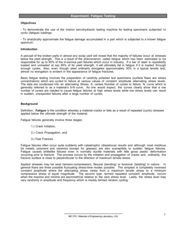
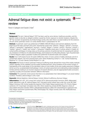
Metallurgical Aspects of Fatigue Failure of Steel-Part IMetallurgical Aspects of Fatigue Failure of Steel-Part IIf a steel containing 0.40% carbon is heated to some temperature above U1 it will become completely austenitic (Fig 8). Oncooling, again to just below U1 (which is called the ‘upper critical temperature’ of the steel), the structure begins to changefrom one which is face-centred cubic to one which is body centred cubic. Consequently, small crystals of body-centred cubiciron begin to separate out from the austenite. These body-centred cubic ferrite crystals retain a small amount of carbon(less than 0.02%). As the temperature continues to fall the crystals of ferrite grow in size at the expense of the austenite,and since ferrite is almost pure iron, it follows that most of the carbon present accumulates in the shrinking crystals ofaustenite. As the temperature falls still farther, the carbon begins to precipitate as cementite. At the same time ferrite is stillseparating out and we find that these two substances, ferrite and cementite, form as alternate layers of pearlite until all theremaining austenite is used up.Any steel containing less than 0.8% carbon will transform from austenite to a mixture of ferrite and pearlite in a similarway when cooled from its austenitic state. Transformation will begin at the appropriate upper critical temperature (givenby a point on CE which corresponds with the composition of the steel) and end at the lower critical temperature of 723 C.The relative amounts of ferrite and pearlite will depend upon the carbon content of the steel (Fig 8), but in every case theferrite will be almost pure iron and the pearlite will contain exactly 0.8% carbon. A steel containing 0.8% carbon will notbegin to transform from austenite on cooling until the point E is reached. Then transformation will begin and end atthe same temperature (723 C). Since the steel under consideration contained 0.8% carbon initially, it follows that the finalstructure will be entirely pearlite. Any steel containing more than 0.8% carbon will have a structure consisting of cementiteand pearlite if it is allowed to cool slowly from its austenitic state.1.4 General Properties of Plain Carbon SteelCarbon steel is by far the most widely used kind of steel. Carbon steel is made into a wide range of products, includingstructural beams, car bodies, kitchen appliances, and cans. In fact, there are 3 types of plain carbon steel and they are lowcarbon steel, medium carbon steel, high carbon steel, and as their names suggests all these types of plain carbon steeldiffers in the amount of carbon they contain. The properties of carbon steel depend primarily on the amount of carbon itcontains. Indeed, it is good to precise that plain carbon steel is a type of steel having a maximum carbon content of 1.5%along with small percentages of silica, sulphur, phosphorus and manganese. Generally, with an increase in the carboncontent from 0.01 to 1.5% in the alloy, its strength and hardness increases but still such an increase beyond 1.5%causes appreciable reduction in the ductility and malleability of the steel.Low carbon steel or mild steel, containing carbon up to 0.25% responds to heat treatment as improvement in the ductility isconcerned but has no effect in respect of its strength properties.Medium carbon steels, having carbon content rangingfrom 0.25 to 0.70% improves in the machinability by heat treatment. High carbon steels contain carbon in the range of0.70 to 1.05%. In the fully heat-treated condition it is very hard and it will withstand high shear and wear and will thus besubjected to little deformation. Moreover, at maximum hardness, the steel is brittle and if some toughness is desired it mustbe obtained at the expense of hardness. Other properties of plain carbon steel are illustrated in Table 1.Table 1Physical properties of plain carbon steelFig. 9 Diagram showing the relationship between carbon content,microstructure and mechanical properties of plain carbon steels in thenormalized condition.Density 103kgm-3Thermal conductivity Nm-2TensilestrengthMNm-2% Elongation0.2% C Steel7.865011.7210350300.4% C Steel7.854811.3210600200.8% C Steel7.844610.82108008Material38 BSRM Seminar on Fatigue Properties of Constructional Steel1.5 The Uses of Plain Carbon SteelsAs shown in Fig.9, the hardness of a plain carbon steel increases progressively with increase in carbon content, sothat generally the low and medium-carbon steels are used for structural and constructional work, whilst the high-carbonsteels are used for the manufacture of tools and other components where hardness and wear-resistance are necessary.Fig.10shows hardness as a function of carbon content for various types of microstructures. Although the hardness-carbonrelationships are shown as lines inFig. 10, they are in fact better represented as bands because many factors maycause variations in hardness in a given microstructure. For example, the strength of low-carbon ferritic microstructures isvery sensitive to grain size, while that of largely pearlitic microstructures is very sensitive to the interlamellar spacing ofcementite and ferrite.BSRM Seminar on Fatigue Properties of Constructional Steel 39
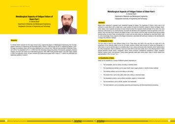
Metallurgical Aspects of Fatigue Failure of Steel-Part IFig. 10 Hardness as a function of carbon content for various microstructures in steels.Metallurgical Aspects of Fatigue Failure of Steel-Part IFig. 11 Schematic representation of the basic types of material failure corresponding to deformation and fractureCrosshatched area shows effect of retained austenite.All types of microstructures increase in strength with increasing carbon content, but martensitic microstructures showthe most dramatic increases. Because of the low solubility of carbon in ferrite (except for as-quenched martensite), thecarbon is primarily concentrated in carbide phases. Therefore, much of the higher strength of medium- and high-carbon steelsis due to higher volume fractions and finer dispersions of carbides in ferrite. Ferritic matrix grain sizes and morphology alsosignificantly affect mechanical behavior at any given carbon level.Fig.10shows that all types of microstructures could beproduced in a steel of a given carbon con tent.2.1 Static loadingWhen a sufficient load is applied to a metal or other structural material, it will cause the material to change shape. Thischange in shape is called deformation. A temporary shape change that is self-reversing after the force is removed, so thatthe object returns to its original shape, is called elastic deformation. In other words, elastic deformation is a change in shapeof a material at low stress that is recoverable after the stress is removed. This type of deformation involves stretching of thebonds, but the atoms do not slip past each other.2. Overview of Mechanical Characterization of MaterialsThe structural materials in service are subjected to loads, or forces. In such real conditions it is necessary to know themechanical properties of the materials in order to avoid excessive deformation and fracture of a structural component.To assure performance, safety and durability of machines, vehicles, nuclear reactors and any structure in general, it isnecessary to prevent excessive deformation of their component parts, and also, cracking that can progress up to producethe complete fracture of the parts must be entirely avoided, or strictly limited. The mechanical properties of materialsare determined by performing carefully laboratory experiments and measurements under conditions similar to the serviceconditions of the particular material. This is the mechanical testing of materials. The mechanical characterization of materials,i.e. the study of their deformation and cracking, is the mean by which the behavior of a structural material in service can bepredicted. The knowledge of the mechanical characteristics or properties of materials provides the basis for preventingfailure of materials in service. Once the mechanical properties of a material are quantitatively determined from mechanicaltests, its chances of success in a particular structural application can be evaluated. The most basic criterion in design toavoid structural failure is that the applied stress in a component must not go above the threshold stress that produces thefailure of the material. It is named strength of the material. When the material failure produces cracking to an extension thata component is separated into two or more pieces, it is named fracture. If the material sample changes in shape or size,the failure is termed deformation. Deformation and fracture present different types of failure according to the causes andmechanisms. The basic types of material failure corresponding to deformation and fracture are given in Fig. 11.40 BSRM Seminar on Fatigue Properties of Constructional SteelBSRM Seminar on Fatigue Properties of Constructional Steel 41
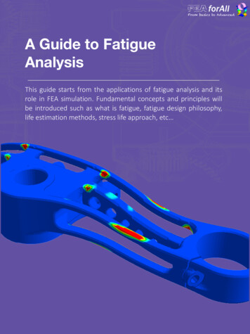
Metallurgical Aspects of Fatigue Failure of Steel-Part IMetallurgical Aspects of Fatigue Failure of Steel-Part I2.2 Cyclic loading2.2.1 Behavior of materials under cyclic loadingThe mechanical response of a material is substantially altered by cyclic loadings. In the case of metals, it dependsgreatly upon hardness of materials and experimental conditions. Under cyclic loading conditions, a metal may harden,soften, remain stable, or have mix behavior (soften or harden depending upon strain level). During constant strain cycling ofa material, an increase in stress with time is called strain hardening and a decrease in stress is called a strain softening.These are related to the nature and stability of the dislocation substructure of a given metallic material. In general, thedislocation density is low for soft materials. For such a material, the increase in the density resulting from cyclic plasticstraining causes strain hardening. Whereas for a hard metal, the cyclic strain causes a rearrangement of dislocations. Theresulting structure for the metal becomes soft as it offers low resistance to deformation. Fluctuating loads are more dangerous than monotonic loads.2.2.2 Cyclic vs Static LoadingTable 2 Key difference between static and cyclic loadingStatic loadingUntil applied stress intensity factor (K)reaches critical stress intensity factor (Kc)(30 MPa m for example) the crack willnot grow.Fig. 12 Schematic representation of deformation of polycrystalline material through slip planes.Cyclic loadingK applied can be well below Kc (3 MPa m for example). Over time, the crackgrows.Key difference between static and cyclic loading are shown Table 2. The design may be safe considering static loads, butany cyclic loads must also be considered.2.2.3 Typical example on the effect of cyclic loading(a)(b)In the Aloha Airlines incident on April 28, 1988, an aircraft operated within the manufacturer’s guidelines suffered acatastrophic failure (Fig. 14). In this case, the aircraft was subjected to a large number of very short flight cycles and consequentlya large number of pressurization cycles for relatively few airframe hours- the end user was flying a very frequent hoppingservice between Hawaiian Islands. This was also predominantly at a relatively low flight level where there was quite a lotof salt water vapor present. The consequence was that the fuselage failed dueto fatigue along rows of rivet holes - stress concentrators. Fortunately, few people died (1?), and so this is a good exampleof the necessity to understand fatigue properly even when simply operating aircraft, in that the normal life and inspectioninterval rules are made with some flight profile assumptions in mind and if you are using the product outside of thoseassumptions, then you may need to check that they are correct.Fig. 13 (a) Typical stress vs. strain diagram with the various stages of deformation and (b) standard tensile specimen beforeand after tensile test.When the stress is sufficient to permanently deform the metal, it is called plastic deformation. Plastic deformation involvesthe breaking of a limited number of atomic bonds by the movement of dislocations. The force needed to break the bondsof all the atoms in a crystal plane all at once is very great. However, the movement of dislocations allows atoms in crystalplanes to slip past one another at a much lower stress levels. Since the energy required to move is lowest along the densestplanes of atoms, dislocations have a preferred direction of travel within a grain of the material. This results in slip that occurs along parallel planes within the grain. These parallel slip planes group together to form slip bands, which can be seenwith an optical microscope. A slip band appears as a single line under the microscope, but it is in fact made up of closelyspaced parallel slip planes as shown in the image (Fig. 12). Under tensile stress, plastic deformation is characterized by astrain hardening region and a necking region and finally, fracture (also called rupture) (Fig. 13). During strain hardening thematerial becomes stronger through the movement of atomic dislocations. The necking phase is indicated by a reduction incross-sectional area of the specimen. Necking begins after the ultimate strength is reached. During necking, the materialcan no longer withstand the maximum stress and the strain in the specimen rapidly increases. Plastic deformation endswith the fracture of the material.42 BSRM Seminar on Fatigue Properties of Constructional SteelFig. 14 Aircraft after landing in the Aloha airlines incident. After 89,090 flight cycles on a 737-200,metal fatigue lets the top go in flight.BSRM Seminar on Fatigue Properties of Constructional Steel 43
Metallurgical Aspects of Fatigue Failure of Steel-Part IMetallurgical Aspects of Fatigue Failure of Steel-Part I3 Fatigue3.1 Introduction to fatigueFatigue failures in metallic structures are a well-known technical problem. Already in the 19th century several seriousfatigue failures were reported and the first laboratory investigations were carried out. Noteworthy research on fatigue wasdone by August Wöhler. He recognized that a single load application, far below the static strength of a structure, did not doany damage to the structure. But if the same load was repeated many times it could induce a complete failure. In the 19thcentury fatigue was thought to be a mysterious phenomenon in the material because fatigue damage could not be seen.Failure apparently occurred without any previous warning. The history of engineering structures until now has been markedby numerous fatigue failures of machinery, moving vehicles, welded structures, aircraft, etc. From time to time such failureshave caused catastrophic accidents, such as an explosion of a pressure vessel, a collapse of a bridge, or another completefailure of a large structure. Many fatigue problems did not reach the headlines of the newspapers but the economic impactof non-catastrophic fatigue failures has been tremendous. Fatigue of structures is now generally recognized as a significantproblem.3.2 Fatigue as a phenomenon in the material(b)In a specimen subjected to a cyclic load, a fatigue crack nucleus can be initiated on a microscopically small scale, followedby crack grows to a macroscopic size, and finally to specimen failure in the last cycle of the fatigue life (Fig. 15). The fatiguefailure occurs after three different stages, namely:Fig. 15 (a) Different phases of the fatigue life and relevant factors and(b) schematic drawing of the fatigue crack propagation.1. Crack initiation at points of stress concentration2. Crack growth3. Final rupture(a)CyclicslipCracknucleationMicro crackgrowthInitiation periodMacro crackgrowthFinalfailureCrack growth periodFig. 16 Cycle slip leads to crack nucleation.KtStress concentration factorKStress IntensityfactorKIcFracturetoughness3.2.1 Crack initiationFatigue occurs at stress amplitudes below the yield stress. At such a low stress level, plastic deformation is limited to asmall number of grains of the material. This microplasticity preferably occurs in grains at the material surface because ofthe lower constraint on slip. On a microscalethe shear stress is not homogeneously distributed through the material. In some grains at the material surface, theseconditions are more favorable for cyclic slip than in other surface grains. If slip occurs in a grain, a slip step will be createdat the material surface (Fig.16a). A slip step implies that a rim of new material will be exposed to the environment. The fresh44 BSRM Seminar on Fatigue Properties of Constructional SteelBSRM Seminar on Fatigue Properties of Constructional Steel 45
Metallurgical Aspects of Fatigue Failure of Steel-Part IMetallurgical Aspects of Fatigue Failure of Steel-Part Isurface material will be immediately covered by an oxide layer in most environments, at least for most structural materials.Such monolayers strongly adhere to the material surface and are not easily removed. Another significant aspect is that slipduring the increase of the load also implies some strain hardening in the slip band. As a consequence, upon unloading(Fig.16b) a larger shear stress will be present on the same slip band, but now in the reversed direction. The same sequenceof events can occur in the second cycle, see Fig.16c and d.Most fatigue cracks grow across grain boundaries (transcrystalline) or along grain boundaries (intercrystalline) dependingon the material, load, and environmental conditions (Fig. 19).Fig. 19 Scanning electron micrographs showing (a) transcrystalline and (b) intercrystalline fatigue cracks.(a) Slip lines are clearly visible(b) Same as in (a) but plastically strained (5%)which opens a microcrack, see arrowFig. 17 Development of cyclic slip bands and a microcrack in a pure copper specimen.Not all fatigue cracks nucleate along slip bands although in many cases slip bands are at least indirectly responsible formicrocracks initiating in metals (Fig. 17). Under fatigue loading conditions, fatigue cracks may nucleate at or near materialdiscontinuities. Discontinuities include inclusions, second-phase particles, corrosion pits, grain boundaries, twin boundaries,pores, voids, and also slip bands. Microcracks in high strength or brittle behaving metals are often formed directly at inclusionsor voids, and then grow along planes of maximum tensile stresses.3.2.2 Crack growthAs long as the size of the microcrack is still in the order of a single grain, the microcrack is obviously present in an elasticallyanisotropic material with a crystalline structure and a number of different slip systems. The microcrack contributes to aninhomogeneous stress distribution on a microlevel, with a stress concentration at the tip of the microcrack. As a result,more than one slip system may be activated. Moreover, if the crack is growing into the material in some adjacent grains,the constraint on slip displacements will increase due to the presence of the neighbouring grains. Similarly, it will becomeincreasingly difficult to accommodate the slip displacements by slip on one slip plane only. It should occur on more slipplanes. The microcrack growth direction will then deviate from the initial slip band orientation. In general, there is a tendencyto grow perpendicular to the loading direction, see Fig.18.Fig. 20 Different scenarios of fatigue crack growth.Fig. 18 Cross section of a microcrack dur
austenite and (d) microstructure of heat treated low-alloy steel showing bainite. 4% picral 2% nital etch. Martensiteis a constituent that is formed by rapid cooling (quenching) plain carbon or low-alloy steels from the high-temperature austenite phase (Fig. 7). Carbon is dissolved in th