Transcription
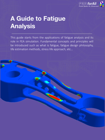
A Guide to FatigueAnalysisThis guide starts from the applications of fatigue analysis and itsrole in FEA simulation. Fundamental concepts and principles willbe introduced such as what is fatigue, fatigue design philosophy,life estimation methods, stress life approach, etc
About the Author:My name is Cyprien Rusu, I am a French CAEengineer who wants to teach the right bases of FEASimulation to designers, engineers and everyoneaspiring to get it right!Hundreds of FEA students followed my free FEAwebinars on Youtube, read my blog articles onfeaforall.com and joined my FEA courses to learnmore and improve their understanding of FEA andbecome better engineers!I have also taught FEA seminars to FEA engineers from all over theworld Do you want to join my free FEA course?Click on the link below and join the course to get a basicunderstanding of the FEA foundations that you need to have:Join the free FEA coursePage 2
1- What is Fatigue Failure?Fatigue failure is defined as the tendency of a material to fractureby means of progressive brittle cracking under repeatedalternating or cyclic stresses of an intensity considerably below thenormal strength.Although the fracture is of a brittle type, it may take some time topropagate, depending on both the intensity and frequency of thestress cycles.Examples of fatigue failureAll structures and mechanical components that are cyclicallyloaded can fail by fatigue.Fundamental requirements during design and manufacturing toavoid fatigue failure are different for each different case andshould be considered during the design phase.Page 2
2- Fatigue Design PhilosophyBefore attempting to carry out a fatigue calculation, or evenchoosing a way of calculating, it is necessary in critical situationsto decide on a design philosophy.The three main approaches are Safe-Life, Fail-Safe and DamageTolerant.Safe-LifeProducts are designed to survive a specific designlife. Full scale tests are usually carried out withmargins of safety applied. Fairly optimized structures.A “safe-life” stool.Any less than three legs and it would fall over!Fail-SafeProducts are designed to avoid any failure regardless ofcosts. If the structure were to fail in some part, it wouldcapable to working properly, until necessary repairscould be made.A “Fail-Safe” stool.Failure of one leg would not result in overall failure.Damage-TolerantProducts are design to take into account inspectioncriterion to investigate the structure periodically to seewhether or not crack have started.A “damage-tolerant” stool.The stool has some built in redundancy and is inspectedregularly.
3- Life Estimation MethodsFatigue analysis itself usually refers to one of two methodologies.The stress-life (or S-N method), is commonly referred to as thetotal life method since it makes no distinction between initiating orgrowing a crack. This was the first fatigue analysis method to bedeveloped over 100 years ago.The local-strain or strain-life (E-N) method, commonly referred toas the crack initiation method, was more recently developed andis intended to describe only the ‘initiation’ of a crack.Total LifeCrack InitiationCrack GrowthAn idealization of the fatigue design processFracture specifically describe the growth or propagation of acrack once it has been initiated and has given rise to many socalled crack growth methodologies.
4- Fatigue LoadingSome load histories may be simple and repetitive, while in othercases they may be completely random. They can also haveconstant or variable amplitudes.For simple cases constant amplitude loading is used to obtainmaterial fatigue behavior/properties for fatigue design.Some real life load histories can occasionally be modeled withconstant amplitude as well.Constant amplitude loading has been introduced below:SatimeStressTension ( )b)Cycle – 2 reversalsSmaxSmSrSmin – minimum stressSmax – maximum stressSa – alternating stress (stress amplitude)Sm – mean stressSr – stress rangeSaSrSmintime(-)Stress(-) CompressionTension ( )a)R – stress ratioR -1R 0fully reversed cyclepulsating tensionExamples of stress cycles, (a) fully reversed, and (b) offset.Stresses can be replaced with load, moment, torque, strain, deflection or stress intensity factors.
5 - Wőhler’s Curve, S-N CurveThis curve has been developed by German August Wőhler for hissystematic fatigue tests done in the 1870’s.S-N Curve plots the diagram of amplitude of nominal stress as afunction of number of cycles to failure for un-notched (smooth)specimens.Mathematical description of the material S-N curve:ASa σa A·Nf-BBσa – applied alternating stressA – constant, value of σa at one cycleB – Basquin’s exponent, slope of the log-log curveNf - the number of cycles of stress that a specimen sustains before failure occurs
6 - Stress Life ApproachStress life method, more commonly known as the S-N or NominalStress method is used for total life calculation.It assumes the structure to be fully elastic (even in local fatiguerelated details like notches). Initiation or growing phase of a crackis not considered. Applicable to high cycle fatigue problems (lowload-long life). This approach should not be used to estimatefatigue lives below 10,000 cycles.Some basic features related to Stress-Life approach:· Material and component S-N curves· Stress concentration factors,· Miner’s cumulative damage theory· Goodman or Gerber mean stress correction· Rainflow Cycles CountingRainflow cycles counting exampleGerber-Goodman diagram
7 - Strain Life ApproachThis method is also called Critical Location (CLA) approach, LocalStress-Strain, E-N or Crack Initiation.It applies when the structure durability depends on stressamplitude of local strain at the crack initiation place. Strain-lifedesign method is based on relating the fatigue life of notched partsto the life of small unnotched specimens cycled to the samestrains as the material at the notch root.This approach is best suited for low cycle fatigue problems,where the applied stresses have a significant plastic component.ΔSΔεCritical zoneSmooth specimenΔεΔSNotchThe concept of similitude between strain controlledtest specimen and a component being designed
8 - Strain Life CurveE-N curve shows the relationship between the strain and thenumber of cycles causing fatigue failure as expressed inequation below.By applying a number of individual strain amplitudes to theE-N curve, which have been extracted through rainflow-counting,each number of cycles and the corresponding individual damagelevel are obtained.Δε/2 – total strain amplitude εaNf - the number of cycles of stress that aspecimen sustains before failure occursE – modulus of elasticityσf’ – fatigue strength coefficientεf’ – fatigue ductility coefficientC – fatigue ductility exponent
Do you want to join my free« FEA Foundations » course?Join the free FEA course
ContactWebsite: feaforall.comEmail: cyprien@feaforall.comTelephone: 82-31-789-4040
2- Fatigue Design Philosophy Before attempting to carry out a fatigue calculation, or even choosing a way of calculating, it is necessary in critical situations to decide on a design philosophy. The three main approaches are Safe-Life, Fail-Safe and Damage-Tolerant. Products are des