Transcription
EN-A01CREATOR PRO 2User GuideThis guide is only applicable to FLASHFORGE Creator Pro 2 3D printer
CONTENTPREFACENOTICEChapter 1: 3D Printing Technology05ProcessChapter 2: About Creator Pro 206About Your Creator Pro 2Unboxing and InstallationThe First SettingTouchscreen Interface IntroductionChapter 3: Slicing Software30InstallationExploring FlashPrintHow to create .g file?Function IntroductionChapter 4: Maintenance50Chapter 5: Support and Service5101
PREFACENote: Each device must be tested before leaving factory. If there are some residues inextruder or some tiny scratches on the build tape, it is normal and won’t affectthe printing quality.On the completion of this User Guide, thanks all FlashForge engineers and the FlashForge3D printer users for their unremitting efforts and sincere assistance.The FlashForge Creator Pro 2 User Guide is designed for the Creator Pro 2 users to starttheir printing journey with FlashForge Creator Pro 2. Even if you are familiar with earlierFlashForge machines or 3D printing technology, we still recommend that please read thisguide, as there is lots of important information about the Creator Pro 2 for you to get abetter 3D printing experience.For a better and more successful printing experience, you can refer to the followingmaterials:· Official FlashForge Website::FlashForge English website:www.flashforge.comThe official FlashForge website contains the up-to-date information concerningFlashForge software, firmware, device maintenance and so on. Users are also able to getthe contact information from there.02
NOTICENotices: Read all the instructions in the manual and familiarize yourself with theFlashForge Creator Pro 2 User Guide before setting-up and using. Failure tocomply with the warning and instructions may result in individual injury, fire,equipment damage or property damage.PLEASE STRICTLY FOLLOW ALL THE SAFETY WARNINGS AND NOTICE BELOW ALL THE TIME.WORK ENVIRONMENT SAFETYKeep your work place tidy.Do not operate Creator Pro 2 in the presence of flammable liquids, gases or dust.Keep Creator Pro 2 out of children and untrained persons' reach.ELECTRICAL SAFETYAlways use the Creator Pro 2 with a properly grounded outlet. Do not refit Creator Pro 2plug.Do not use Creator Pro 2 in damp or wet locations. Do not expose Creator Pro 2 toburning sun.In case of device damage, please use the power supply provided by FlashForge.Avoid using the device during an thunderstorm.In case of uncertain accident, please unplug the power of device if you do not use it forlong.PERSONAL SAFETYDo not touch the nozzle and build plate during printing.Do not touch the nozzle after finishing printing.Dress properly. Do not wear loose clothing or jewelry. Keep your hair, clothing andgloves away from moving parts.Do not operate the device while you are tired or under the influence of drugs, alcoholor medication.CAUTIONSDo not leave the device unattended for long.Do not make any modifications to the device.To lower the build plate before loading/unloading filament. (The distance betweenthe nozzle and build plate should be kept for at least 50mm)Operate the device in a well-ventilated environment. Some filament may produceodors during the printing process.Never use the device for illegal activities.Never use the device to make any food storage vessels.Never use the device to make any electrical appliance.Never put the model into your mouth.Do not remove the models with force.Never connect the device with network cable longer than 3m.03
ENVIRONMENT REQUIREMENTSTemperature: RT 15-30 Moisture: 20%-70%PLACE REQUIREMENTSThe device must be placed in a dry and ventilated environment. The distances of theleft, right and back side space should be at least 20cm, and the distance of the frontside space should be at least 35cm.FILAMENT REQUIREMENTSPlease make sure you use the FlashForge filament or the filament from the brandsaccepted by FlashForge.FILAMENT STORAGEAll polymers degrade with time. Do not unpack until filament is needed. Filamentshould be stored at clean and dry conditions.LEGAL NOTICEAll the information in this document is subject to any amendment or change withoutthe official authorization from FlashForge.FLASHFORGE CORPORATION MAKES NO WARRANTY OF ANY KIND WITH REGARD TO THISDOCUMENT, INCLUDING, BUT NOT LIMITED TO, THE IMPLIED WARRATIES OF MERCHANTABILITY AND FITNESS FOR A PARTICULAR PURPOSE.Flashforge is not responsible for any safety accident caused by disassembly ormodification of equipment by the customer. FlashForge shall not be liable for errorscontained herein for incidental consequential damages in connection with furnishing,performance or use of this material.Flashforge reserves the right to modify the User guide due to subsequent equipmentupdates.Copyright 2020 Zhejiang Flashforge 3D Technology Co,. Ltd All Rights Reserved04
Chapter 1: 3D Printing Technology3D printing refers to transforming three-dimensional models into physical objects thatyou can hold and touch. It is also called additive manufacturing, because the 3D model iscreated by “adding”layers upon layers of material until the object is fully fomed.Fused Filament Fabrication(FFF) is the most common method of 3D printing. It is also themethod that the Creator Pro 2 uses. It works by melting plastic material called filamentonto a print surface in high temperature. The filament solidifies after it cool down, whichhappens instaneously after it is extruded from the nozzle. 3D object are formed with thefilament laying down multiple layers.1.1Process3D printing involves three steps:1.Make or download a 3D model.2.Slice and export the 3D model.3.Build the 3D model.1.1.1 Make a 3D ModelCurrently, there are three ways of making a 3D model.Designing From Scratch:You can use free CAD(computer-aided design)software such as3DTADA, AutoCAD, SolidWorks, Pro-E.3D Scanners:An alternative method to making a 3D model is to scan an object. 3Dscanners work by sigitizing a physical object, collecting its geometric data, and saving itto a file on your PC. There are also apps that can turn a mobile device into a 3D scanner.From the Website:The most popular way of obtaining a 3D model is to download it fromwebsites that allow users to upload 3D models that they designed.E.g: www.thingiverse.com1.1.2 Slice and Export the 3D ModelSlice software is the software that prepares 3D models for printing and turns theminto instructions for the 3D printers. FlashPrint is the slicing software used for theFlashForge Creator Pro 2.Using FlashPrint, you can prepare .stl files to be .x3g files for printing. Then users canprint files via SD card.1.1.3 Build the 3D ModelOnce the output file has been transferred to your Creator Pro 2, it will start to turn the3D model into a physical object by laying down layers of filament.05
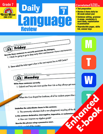
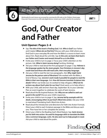
Chapter 2: About Creator Pro 22.1About Your Creator Pro 22.1.1 Views10 11679812 1314171234518192015161. Platform4. LCD panel7. X-axis guide rod10. Spring presser13. Turbofan baffle16. USB cable input19. Spool holder212. Platform support5. Z-axis guide rod8. Slot11. Cooling fan14. Extruder bracket17. Filament guidetube buckle20. Power input063. Leveling nut6. Extruder cable bunch9. Nozzle cooling fan12. Nozzle15. SD card slot18. Spool holder slot21. Power switch
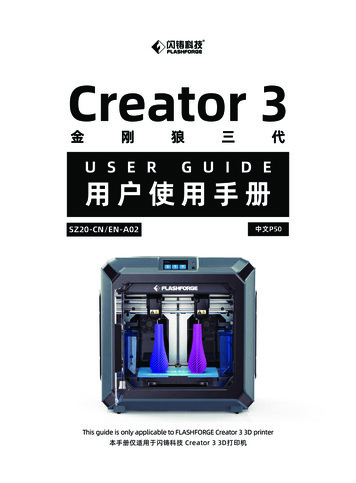
2.1.2 AccessoriesCREATOR PRO 2 金刚狼 PRO 2Creator Pro 2FilamentTop coverAfter-salesService CardPower CableUSB CableSD CardSpool HolderBuild TapeScrew DriverStampingWrenchAllenWrenchUncloggingPin ToolScraperPTFE TubeFilamentGuide TubeGreaseGlue StickAnti- oozingplateLeveling CardLeveling Nut07Quick StartGuide
2.1.3 TermsBuild PlateThe surface on which the Creator Pro 2 builds an object.Build TapeThe blue tape that covers Creator Pro 2’s build plate so thatthe object can stick to the build plate well. Please change itwhen the adhesion is not good.Build VolumeThe three dimensional amount of space that an object will useonce it is completed. The largest build volume of Creator Pro 2is 200*148*150mm.Leveling NutsNuts under the platform that are used for adjusting thedistance between the nozzle and build plate.ExtruderNozzleFilament IntakeFilament Guide TubeStamping WrenchUnclogging Pin ToolThe device that draws the filament from the spool, meltsit and extrudes it through a nozzle onto the build plate.Also called“print head”, which located at the bottom of theextruder where heated filament is squeezed out.An opening located at the top of the extruder.A plastic piece that guides the filament from the filamentbox to the filament intake.A tool that used for seizing the nozzle’s metal cube.A tool that used for cleaning and unclogging the extruder.2.1.4 Product ParametersNameNumber of ExtruderPrint TechnologyCreator Pro 22(independent)Fused Filament Fabrication(FFF)Screen3.5’’ Touch ScreenBuild Volume200*148*150mm;Mirror mode:80*148*150mm; Duplicate mode:95*148*150mmLayer ResolutionBuild AccuracyPrint FilamentFilament DiameterNozzle DiameterPrint SpeedSoftwareSupport FormatAC InputConnectivityInternal Storage0.1-0.4mm ntInput:3MF/STL/OBJ/FPP/BMP/PNG/JPG/JPEG Output:GX/GInput:100-240VAC,47-63Hz; Power:320wSD card,USB cableNo08
2.2Unboxing and Installation2.2.1 UnboxingThe Creator Pro 2 was carefully packaged at FlashForge manufacturing facility. Pleasefollow the unpacking steps laid out below.CAUTION1. Remove the package and take out accessories carefully. Do notuse force.2. Do not tear the yellow high temperature resistant adhesive tapearound the nozzle, it has thermal insulation and high temperatureresistance characteristics.1. Open box and remove top foam piece.2. Firmly grasp the two side handles ofFlashForge Creator Pro 2. Lift it out of thecarton and place it on a stable surface.3. Remove the packing bag and thenremove the tape and plastic wrap forprotecting the front door.4. The accessories shall be displayed. Letus remove the inner package and takethe accessories out.09
5. Take the extruder out and place theextruder carefully. Avoid the nozzle totouch the desk, which prevent the nozzledamage from scratch.6. Take out the foam with accessories.Shear two ties on the both sides ofX-axis guide rod.7. Open the door, remove top cover of theprinter and take filament out of the lid.8. Hold both sides of the printing platform,and slowly lift the platform from thebottom to facilitate the removal of thefoam box below.9. Take out the foam on the bottom of theplatform, and then slowly press theplatform down by hands to the lowerposition for easy subsequent installation.10. Unpacking is complete. It is recommended that you keep the packagingmaterials for later handling or storage.10
2.2.2 Installation1.Extruder Assembly1. Lower the platform first and place thedual extruder on the extruder seat.2. Take the M2.5 Allen Wrench from thetool bag and four M3 bolts from theaccessory kit.3. Adjust the extruder location to align thebolt holes.Bolt Hole4. Secure the extruder onto the extruderseat by screwing the M3 bolts in.11Bolt Hole
2.Filament Guide Tube and Filament Installation1.To install a spool holder, level it and insert the end into the corresponding opening.2.Turn down the spool holder to make the holder bottom cleave to the printer back.Please refer to the next page for theright method of filament mounting.3.Take a roll of filament, then squeeze the spool holder top and mount the filament spoolto the holder.12
Tips1. The filament spool must be orientedcorrectly (see below).Filament GuideTube Buckle2. After filament guide tube fixationcompleted, press the left spring presserof extruder, put filament vertically intothe left filament intake from the otherend of filament guide tube.limited seatLock the filament guide tube with R-shapebuckles.Note: Please pay attention to extend the guide tube to the inside of the spool to preventthe filament from being entangled and being wrapped outside the spool.3.Install Top Cover4.Install Anti-oozing PlateM3x8Fixed the anti-oozing plate by two screws.Please make sure that the nozzle touches theanti-oozing plate properly when installed. It isOK to adjust the distance between the nozzleand plate manually. It is normal to see scratcheson the surface of the plate after printing forseveral times.Install top cover for printing ABS; removethe top cover for printing PLA.13
The First Setting2.32.3.1 Loading and sAboutManualTools1. Tap [Tools]-[Filament]L ExtruderR ExtruderLoadLoadUnloadUnloadHeating.L Extruder75 / 220 2. Tap [load], the extruder will start to heat up. After heating to the target temperature,please manually insert the filament into the filament feeding wheel. When the filamentis ejected from the nozzle, it indicates that loading is completed.3. Tap [unload], the extruder starts to heat up. After heating to the target temperature,manually feed out a part of filament from the nozzle, then press down the springpresser, quickly pull out the filament, and complete unloading.14
2.3.2 LevelingClearing the remaining materials on the nozzle first to avoid leveling ase wait, device is homing.Next1. Tap [Tools]-[Level] to start leveling. The machine will finish homing first.Screw the three nuts tnder the platformcounterclockwise until they are tight, thentap the [Next].Next2. After stop movement of extruder and platform, tighten the three nuts below theplatform counterclockwise (To avoid scratch build plate by extruder and it is importantaction)Please adjust the front thumb screw underPlatform when stop.Next3. Choose one extruder and move it to the first nut by hand. Place a paper under theextruder and tighten the nut to reduce the distance between extruder and platform.Gently move the paper and feel the fraction. If move the paper with gent fraction, it is asuitable distance between extruder and platform. Finished the first place, and repeatthe same actions in the second and third nut.Note: the small distance between the extruder and platform causes removing printedobjects hard, while big distance causes adhesion fails or wrapping.15
2.3.3 XYZ Axis CalibrationZ Axis tusAboutManualTools1. Tap [Tools]-[Setting]-[Z calibration]. Creator Pro 2 uses a compensation layer mechanism. Instead of manually adjusting the installation positions of the left and rightnozzles, a program is used to calculate the height difference between the two ModeLanguageFactoryResetZ CalibrationInitializing moving.2. The extruder and platform will return to the zero position first, select any extruder tocalibrate. When the temperature of the nozzle and the platform is too high, it will waitfor the nozzle to cool down to 50 C to prevent the nozzle from scalding the build tape.Please tap Z-,Z to adjust andput the leveling card betweennozzle and platform to verify aproper distance.Z:0.08ZZ OK3. Follow the on-screen instructions and insert the leveling card between the nozzle andthe platform, please click Z- or Z to adjust the appropriate spacing. The adjustmentrange is sliding leveling paper. If you feel a little frictional resistance, it indicates thatthe distance between the nozzle and the platform is appropriate. When one extruder isadjusted, it will be switched to another extruder for calibration.Note: Do not turn the nuts under the platform during Z-axis calibration.16
X Axis CalibrationX-axis calibration: Used to adjust the consistency of the two extruders in the X-axisdirection to prevent misalignment during tModeLanguageFactoryResetX CalibrationL: 152/200R: 164/200B: 45/501. Tap [Setting]-[X Calibration], or continue the X-axis calibration after the Z-axis calibration is completed. After the machine initialization movement is completed, the nozzleand the platform will be heated. At this time, please ensure that the filament has beeninserted into the extruder.2. After heating, left and right extruders print a line one by one.Please tap X-,X to adjust and verify makesure the lines are aligned.XX-R0.00LLX VerifyX RX LRLROK3. According to the actual printed lines, click X-, X to adjust the bias of the extruders andremove the printed lines; tap the verify button, the left and right extruders will print thelines again to see if the lines coincide, if they coincide, it means that the X-axiscalibration is completed, if they are inconsistent, continue to adjust, until it coincides.17
Y Axis CalibrationY-axis calibration: Used to adjust the consistency of the two extruders in the Y-axisdirection to prevent misalignment during tModeLanguageFactoryResetY CalibrationL: 152/200R: 164/200B: 45/501. Tap [Setting]-[Y Calibration], or continue the Y-axis calibration after the X-axis calibration is completed. After the machine initialization movement is completed, the nozzleand the platform will be heated. At this time, please ensure that the filament has beeninserted into the extruder.2. After heating, left and right extruders print a line one by one.Please tap Y-,Y to adjust and verify makesure the lines are aligned.Y 0.00Y-Y LY-RVerifyLLY-RRLOKR3. According to the actual printed lines, click Y-, Y to adjust the bias of the extruders andremove the printed lines; tap the verify button, the left and right extruders will print thelines again to see if the lines coincide, if they coincide, it means that the Y-axiscalibration is completed, if they are inconsistent, continue to adjust, until it coincides.18
2.3.4 First PrintAfter installing, loading filament and calibrating, it start your first print.1. Insert the SD card to the side of rge2. Tap [Print]-[SD card]; choose the test file to print.19
2.3.5 Remove ModelsWarm!Drop the platform down first before removing the model. Please pay attentionto the direction of shoveling to avoid scratches by using the scraper knife.Do not damage the build plate when removing models.The scratch on the build platemay cause print fails.· Model coolingPrint model on the build plate without glum. Only after cold down the printed objectsand build plate,remove the models easily.· Using scraper knifeAfter cooling, the printed object is still attached to the platform, and you can use ascraper knife to remove the printed product. Keep the blade parallel to the printingplatform, slightly insert from the bottom of the model and remove the model with alittle force.2.3.6 Remove SupportsRemoving PVA supports needs post-procession. Put the PVA supports model into thewater to dissolve supports.1. Put the printed objects into the waterPut the printed objects with PVA supports into the water and dissolve PVA supports.There are some methods to speed up dissolve.· Using warm water to speed up dissolve PVA. If the main structure of printed objects isPLA, it ensures the temperature of warm water should not over 35 C to avoid printedobjects shape deformation.· Stir water. The moving water can speed up solution of PVA.· Soak printed objects in the water about 10 mins, and remove supports by pincers. Thenput the printed objects into the water and dissolve remaining PVA easily.2. Rinse with waterAfter the PVA support is completely dissolved, rinse the model with water to remove theremaining PVA.3. Dry modelLet the model dry completely and perform additional post-processing on the objects ifnecessary.4. Waste water treatmentBecause PVA is biodegradable, it is easy to dispose of waste water afterwards. Afterdisposing of the waste water, flush it with hot water for 30 seconds to remove excessPVA in the drain pipe and avoid blockage. Water can be used repeatedly to soakmultiple models, but may increase the dissolution time. Therefore it is recommended touse fresh water to achieve the best effect.20
2.3.7 Material CompatibilityCreator Pro 2 have two independent extruders and support PLA, ABS, HIPS and PVA.Combination mode:PVA PLAHIPS ABSPLA PLAABS ABSFlashforge materials is the best recommended, even Creator pro2 support openmaterials brands. All Flashforge materials have been tested and the best printedparameters have been used in the FlashPrint.PVA filament is water-soluble and has strong water absorption. The filament may softenafter absorbing water, and it is easy to fail printing. Place PVA filament in a dry box whenprinting. PVA storage requires sealed and dry storage.For best results, each material requires different settings.If you use FlashPrint to slice the model, these settings will be automatically set correctlywhen the correct print extruder and material are selected.Adaptability of materials parametersDifferent filament brands have different material characteristics.So it is recommended touse the expert mode to fine-tune the parameters to ensure a good print quality.· Thicken the first layer thickness. It is better to adhesion to platform by adding the firstlayer filament output.· Set the platform temperature to 30 C, when printed small PLA model or the environment temperature is higher over 25 C.· Set the platform temperature to 50 C, when printed big PLA model or the environmenttemperature is lower over 10 C.· The open printing chamber is good for PLA printing and remove the top cover.· The closed printing chamber is good for ABS printing and close the top cover to avoidfilament cracking.· It is advised to decrease to 40% of standard printing speed. Place PVA filament in a drybox to avoid printing fails by absorbing water in the air.21
Touchscreen Interface Introduction2.4Print orge1. Insert the SD card to the side of machine;SD card must be inserted the Creator Pro 2when printing, whether get print file form SD card or connect with flashprint throughUSB cable.Tap [Print]-[SD card] and choose files to print.flashforge test--plaPrint Time0:00L Extruder24 / 205 R ExtruderPlatformflashforge test--plaPrint Time0:00L Extruder24 / 205 R Extruder 224 / 205 0 / 205 524 30 / 50 Platform30 / 50 0%2. Tap temperature of extruder or platform on the touchscreen to modify.22YesNo0%
flashforge test--plaFilament0:00Stop/ Left24 205 Print TimeL Extruder0%24 / 205 Stop Right30 / 50 R ExtruderPlatformCancel3. Tap [More] to stop print or change filament in the process of printing.Preheat InterfaceL ExtruderON240 R ExtruderON240 PlatformOFFStart120 L ExtruderON240 R ExtruderON4240 0Platform2OFF120 YesStartNo1. Tap [Preheat] to preheat the extruder or platform; Setting the targeted heat temperature by tap the touchscreen.L Extruder240 / 240 R Extruder240 / 240 Platform120 / 120 Stop2. Tap [Stop] to stop heat; Tap back arrow to back to the superior window; When reachingthe targeted heat temperature and there is no more action, the preheat will stop.23
Tools sAboutManualToolsTools interface included filament, level, Home, Manual, Setting, Status and About.L ExtruderR ExtruderLoadLoadUnloadUnloadHeating.L Extruder75 / 220 [Filament]Filament load and unload lease wait, device is homing.Next[Level]Adjust platform flatness by manual leveling.24
Screw the three nuts tnder the platformcounterclockwise until they are tight, thentap the [Next].NextAfter stop movement of extruder and platform, tighten the three nuts below the platformcounterclockwise (To avoid scratch build plate by extruder and it is important action)Please adjust the front thumb screw underPlatform when stop.Level Adjustment Finished!NextFinishChoose one extruder and move it to the first nut by hand. Place a paper under theextruder and tighten the nut to reduce the distance between extruder and platform.Gently move the paper and feel the fraction. If move the paper with gent fraction, it is asuitable distance between extruder and platform. Finished the first place, and repeat thesame actions in the second and third nut.Homing! Please wait.Homing Finished.YesYesCancel[Home]Tap [Home] and machine come back to the zero of movement.25Cancel
Y XR-XR:0.00XR XL-XL Z-XL:-135.00Y:0.00Z:20.00Z Y-[Manual]Tap the touchscreen to control XYZ axis tModeLanguageFactoryReset[Setting]Setting interface included X calibration, Y calibration, Z calibration, Expert mode,Language and xpertModeLanguageFactoryReset[X calibration], [Y calibration], [Z calibration]Learn more on chapter 2.3.3.26
Manual fine calibrationThis assistant is for advanced users only.After a printer calibration. Fine-tune thecalibration offsets of X or Y axis if needed.Next[Expert Mode]Simplified calibration for experienced users in the expert mode. According to thedeviation value of the model printed by two extruders on the same axis, the users adjustthe place of exrtuder on the X or Y axis.Manual fine calibrationX-0.00X Y-0.00Y X-RXLLY-RLRLROKWhen the left extruder prints to the right on the X axis,tap X- ; When the left extruderprints to the left on the X axis,tap X .When the right extruder prints to the left on the Y axis,tap Y- ; When the right extruderprints to the right on the X axis,tap Y �本語Deutsch한국어[Language]Support Chinese, English, Japanese, Germany, French and Spanish.27
Confirm CalibrationReset the default value oryReset]After tapping, all settings will be restored to the factory settings.L Extruder:159 R Extruder:135 Platform:45 XR:138.24XL:-138.24Y:-77.50Z:31.00[Status]Extruder and platform temperature, and XYZ axis coordinates show in the status. Click onthe lamp status bar, the ambient light in the cavity of the device will change according tothe settings.Machine Name:My 3D PrinterMachine Type:Flashforge Creator Pro 2Firmware Version:V1.2 20200420Print Volume:200x148x150Usage counter:58hoursTool Count:2[About]The basic information of the device is displayed. The details of the information are subjectto the actual display of the device.You can view the device firmware version number; print volume size; cumulative printingtime, etc.Note: Please offer series number to the after-sales engineers, when you applied forafter-sales service.28
[Firmware Upgrade]Method 1:Insert the SD card to the computer and build a folder called sys. Copy the firmware filesinto the sys folder. Then insert the SD Card to the machine. Start the machine andupgrade the firmware. After finishing the firmware, delete the sys folder.Method 2:Upgrade the firmware with FlashPrint via USB cable.29
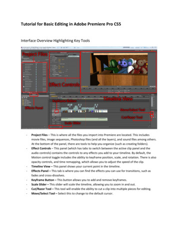
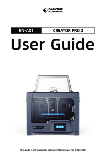
Chapter 3: Slicing SoftwareUsing slicing software FlashPrint to process .stl File and .obj File to .g file, which canbe printed by Creator Pro 2.3.1Installation3.1.1 How to get FlashPrint?There are two ways to get FlashPrint software:Method 1: To get the installation package from the SD card in the accessory kit.Method 2: Visit website www.flashforge.com, and download the latest venison inDownload Center.3.1.2 How to start-up?Decompress the zipped file or start the installation program, and then install the softwareaccording to the direction.Start the software with the start menu shortcut by left double clicking.3.2Exploring FlashPrintNote:Creator Pro 2 support printing by FlashPrint with USB cable.3.2.1 Machine Type SelectionAttention! After starting FlashPrint, you need to select the targeted machine type first.When you start FlashPrint, a dialog box will pop up. Just need to select FlashForgeCreator Pro in the machine type list and click [OK]. You can also change the machinetype via clicking [Print]--[Machine type]. Showed the picture below:Flashprint - untitle.fppFlie(F)Edit(E)Print(P) View(V) Tools(T) Help(H)PrintMachine TypeCtrl PFlashForge Creator Pro 2FlashForge Creator ProFlashForge Creator 3FlashForge DreamerFlashForge FinderFlashForge GuiderFlashForge Guider II30
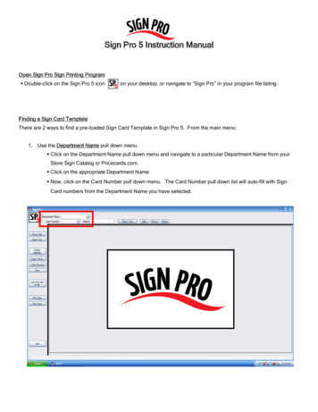
3.2.2 FlashPrint IntroductionFlashprint - untitle.fppFile(F)Edit(E)Print(P) View(V) Tools(T) ateScaleBuild PlatformCutExtruderFlashForge Creator Pro 2Load:Only load one file onceSupport:Enter into the support edit modePrint:Print it directly with your CreatorPro or export to your USB StickView:View FlashPrint home screen fromone of six viewing anglesMove:Move model around on XY- axis; shift click to move along Z axisRotate:Turn and rotate your modelScale:Scale the size of your objectCut:Cut model into several partsExtruder:Chose left or right extruder beforesetting parameter31
3.2.3 LoadYou can load a model file or Gcode file into your FlashPrint by the following six methods:Method 1: Click the Load icon on the main interface. Then select the object file.Method 2: Select the file for loading and drag the file to the main interface of thesoftware.Method 3: Click [File]--[Load File]. Then select the object file for loading.Method 4: Click [File]--[Examples] to load the example files.Method 5: Click [File]--[Recent Files] to load the files opened recently.Method 6: Select and click-drag the target file to the icon of FlashPrint.Note: 3D models can be stored as .STL, .OBJ, and .FPP file and support editing byFlashPrint.Extended:How to create Rilievo?Load a png, jpg, jpeg, bmp picture file into the FlashPrint. And the following dialoguebox will pop up. The setting box includes settings for shape, mode, maximum thickness,base thickness, bottom thickness, width, height, top diameter and bottom diameter.Convert image to stlMiximum dth(X):100mmDepth(Y):100mmShape:Mode:Base Thickness:OKCancelShape: including plane, tube, canister, seal and lamp.Mode: including “darker is higher” and “lighter is higher”.Maximum thickness: Z value of the model.Base thickness: The minimum raft thickness and the default value is 0.5mm.Width: X
Keep Creator Pro 2 out of children and untrained persons' reach. PLEASE STRICTLY FOLLOW ALL THE SAFETY WARNINGS AND NOTICE BELOW ALL THE TIME. WORK ENVIRONMENT SAFETY Always use the Creator Pro 2 with a properly grounded outlet. Do not refit Creator Pro 2 plug. Do not use Creator Pro 2 in damp or wet l