Transcription
Allegiant LightbarTMInstallation, Maintenance,and Service Manual25500456REV. A0 0318Printed in U.S.A. Copyright 2018 Federal Signal Corporation
Limited WarrantyThis product is subject to and covered by a limited warranty,a copy of which can be found at www.fedsig.com/SSG-Warranty.A copy of this limited warranty can also be obtained by writtenrequest to Federal Signal Corporation, 2645 Federal Signal Drive,University Park, IL 60484, email to info@fedsig.com orcall 1 708-534-3400.This limited warranty is in lieu of all other warranties, express orimplied, contractual or statutory, including, but not limited to thewarranty of merchantability, warranty of fitness for a particularpurpose and any warranty against failure of its essential purpose.2645 Federal Signal DriveUniversity Park, Illinois 60484-3167www.fedsig.comCustomer SupportPolice/Fire-EMS:Work Truck:800-264-3578 1 708 534-3400800-824-0254 1 708 534-3400Technical Support800-433-9132 1 708 534-3400
ContentsChapter 1: Safety Messages. 5Safety Message to Installers and Service Personnel of Warning Lights.5Safety Messages to Operators of Federal Signal Sound/Light Systems.8Chapter 2: An Overview of the Allegiant Lightbar. 10LED Lights, Colors, and Flash Patterns.10Electrical System.10Controller Options.10Ambient Light Sensor/AutoDim Option. 11Product Specifications. 11Chapter 3: Reprogramming the Lightbar. 14Reprogramming the Lightbar.14Serial Bars:.14Discrete Bars:.15Making the Electrical Connections for Reprogramming.15Reprogramming the Discrete Lightbar .15Chapter 4: Wiring the Allegiant Lightbar in the Vehicle . 18Planning the Electrical Installation.18Connecting Power to the Lightbar .19Chapter 5: Maintaining and Servicing the Allegiant. 26Servicing the Lightbar Domes.26Cleaning the Lightbar Lens or Dome.26Removing and Reinstalling the Lightbar Dome .27Replacing a PCB.28Resetting the Controller.30Getting Technical Support and Service.33Getting Repair Service.33Ordering Replacement Parts.34Allegiant Lightbar3
ContentsFiguresFigure 2.1 Lightbar Positions. 12Figure 4.1 Power and cable connections. 20Figure 4.2 Relay for isolating devices with large filter capacitors. 21Figure 4.3 SignalMaster 331105 controller (external SignalMaster control). 22Figure 4.4 SmartSiren SS2000SM Series controller (external SignalMaster control). 23Figure 4.5 SignalMaster control functions wired to ground for external Serial Interface Module control. 24Figure 4.6 SignalMaster control functions wired to 12 Vdc for Internal control. 25Figure 5.1 Four barrel nuts in passenger-side end dome. 27Figure 5.2 Locations of ROC PCBs (53" shown). 28Figure 5.3 ROC Connections. 29TablesTable 2.1 Dimensions.11Table 2.2 Light Specifications.11Table 2.3 Electrical and Temperature.11Table 2.4 Lightbar functions. 13Table 3.1 Wire functions and fuse requirements. 15Table 3.2 Allegiant Patterns. 16Table 3.3 Allegiant Discrete Mode 2 Patterns. 16Table 4.1 SignalMaster control wires and warning patters (Internal SM control). 21Table 4.2 Cross reference for controller leads (external Serial Interface Module control). 22Table 5.1 Troubleshooting tips. 31Table 5.2 Replacement parts. 344Allegiant Lightbar
Chapter 1: Safety MessagesFor your safety, read and understand this manual thoroughly before installing, operating,and servicing the Allegiant lightbar. The safety messages presented in this chapter andthroughout the manual are reminders to exercise extreme care at all times. In addition, readand understand the safety instructions and keep it close at hand for reference. To downloadcopies of this manual, go to www.fedsig.com or call the Federal Signal Service Department at1-800-433-9132, 7 am to 5 pm, Monday through Friday (CT).Safety Message to Installers and Service Personnel of Warning LightsBefore Installation or ServiceQualifications To properly install or service this equipment, you must have a good understanding ofautomotive mechanical and electrical procedures and systems, along with proficiency inthe installation and service of safety warning equipment. Always refer to the vehicle’sservice manuals when performing equipment installations on a vehicle.Light Hazards In order to be an effective warning device, this product produces bright light that can behazardous to your eyesight when viewed at a close range. Do not stare directly into thislighting product at a close range or permanent damage to your eyesight may occur. Do not install the light system in an area that would block, impair or blind the driver’svision. Ensure that the light system is mounted in a position that is outside of the driver’sfield of vision, so the driver can maintain safe vehicle operation. Federal Signal power supplies and light heads are designed to work together as a system.Combining light heads and a power supply from different manufacturers may reducethe warning effectiveness of the lighting system and may damage the components. Youshould verify or test your combination to make sure the system works together and meetsfederal, state and local standards or guidelines.Electrical Hazards Strobe systems present a shock hazard because they use high voltage to operate. Do nothandle strobe cables, the power supply or bulbs or remove the lens while the equipmentis connected. Strobe systems can also hold their charge even after they have been turnedoff. After disconnecting power to the unit, wait five minutes before handling any parts ofthe strobe system. A light system is a high current system. In order for the system to function properly, aseparate negative (-) connection and positive ( ) connection must be made. All negativeconnections should be connected to the negative battery terminal and a suitable fuseshould be installed on the positive battery terminal connection as close to the batteryas possible. Ensure that all wires and fuses are rated correctly to handle the device andsystem amperage requirements.Allegiant Lightbar5
Chapter 1: Safety Messages Never attempt to install aftermarket equipment that connects to the vehicle wiring,without reviewing a vehicle wiring diagram available from the vehicle manufacturer.Ensure that your installation will not effect vehicle operation or mandated safetyfunctions or circuits. Always check the vehicle for proper operation after installation. The lighting system components, especially light bulbs, strobe tubes, LEDs and the outerhousing get hot during operation. Be sure to disconnect power to the system and allowthe system to cool down before handling any components of the system. Halogen light bulbs and strobe tubes are pressurized and if broken, can burst and resultin flying glass. Always wear gloves and eye protection when handling these components. DO NOT mount a radio antenna within 18 inches of the lighting system. Placing theantenna too close to the lighting system could cause the lighting system to malfunctionor be damaged by strong radio fields. Mounting the antenna too close to the lightingsystem may also cause the radio noise emitted from the lighting system to interfere withthe reception of the radio transmitter and reduce radio reception. DO NOT attempt to wash this or any other electrical device while it is connected to itspower source. Exposure to liquid while the product is connected to the power sourcemay result in an electrical shock and personal injury and may short circuit and damagethe product.During Installation and Service6 DO NOT get metal shavings inside the product. Metal shavings in the product can causethe system to fail. If drilling must be done near the unit, place an ESD approved coverover the unit. Inspect the unit after mounting to be sure there are no shavings present inor near the unit. To avoid a battery explosion, always disconnect the negative battery cable first andreconnect it last. Avoid causing a spark when connecting near or to the battery. The gasesproduced by a battery can cause a battery explosion that could result in vehicle damageand serious injury. DO NOT connect this system to the vehicle battery until ALL other electricalconnections are made, mounting of all components is complete, and you have verifiedthat no shorts exist. If the wiring is shorted to the vehicle body or frame, high currentconductors can cause hazardous sparks resulting in electrical fires or flying molten metal. DO NOT install equipment or route wiring (or the plug in cord) in the deployment pathof an airbag. If a vehicle seat is temporarily removed, verify with the vehicle manufacturer if the seatneeds to be recalibrated for proper airbag deployment. Before mounting any components, check the manual to be sure that the component youare installing is suitable for use in that area of the vehicle. Many components are notsuitable for use in the engine compartment or other extreme environmental exposureareas. The service life of light bulbs and strobes tubes will be shortened if the glass portion istouched during installation. Use gloves when handling these components. If the glassportion has been touched, clean the glass carefully with isopropyl alcohol.Allegiant Lightbar
Chapter 1: Safety Messages When drilling into a vehicle structure, be sure that both sides of the surface are clearof anything that could be damaged. All drilled holes should be deburred and all sharpedges should be smoothed. All wires going through drilled holes should be protected bya grommet or convolute/split-loom tubing. Additionally, all exterior drilled holes mustbe sealed with Motorcraft seam sealer T-A-2-B or equivalent to prevent the potentialexposure to carbon monoxide or other potentially harmful fumes. Failure to observe thiswarning could cause serious injury or death. Because vehicle roof construction and driving conditions vary, do not drive a vehiclewith a magnetically mounted warning light installed. The light could fly off the vehiclecausing injury or damage. Repair of damage incurred because of ignoring this warningshall be the sole responsibility of the user. To avoid denting the roof of the vehicle, place the lightbar mounting feet as close toouter edge of the roof as possible. Roof damage can occur if the hook adjustment bolts are over-tightened. Torque theadjustment bolts 6 ft-lb to 7 ft-lb. Install keeper plates. Locate the light system controls so the VEHICLE and CONTROLS can be operatedsafely under all driving conditions.After Installation or Service After installation, test the light system to ensure that it is operating properly. If a seat is temporarily removed, verify with the vehicle manufacturer if the seat needs tobe recalibrated for proper airbag deployment. Test all vehicle functions, including horn operation, vehicle safety functions and vehiclelight systems, to ensure proper operation. Ensure that the installation has not affected thevehicle operation or changed any vehicle safety function or circuit. Scratched or dull reflectors, mirrors or lenses will reduce the effectiveness of thelighting system. Avoid heavy pressure and use of caustic or petroleum based productswhen cleaning the lighting system. Replace any optical components that may have beenscratched or crazed during system installation. Do not attempt to activate or de-activate the light system control while driving in ahazardous situation. You should frequently inspect the light system to ensure that it is operating properly andthat it is securely attached to the vehicle. After installation and testing are complete, provide a copy of these instructions toinstructional staff and all operating personnel. Do not use a pressure washer to clean the lightbar. Failure to heed this notice willdamage the lightbar. File these instructions in a safe place and refer to them when maintaining and/or reinstalling the product.Failure to follow all safety precautions and instructions may result in property damage,serious injury, or death.Allegiant Lightbar7
Chapter 1: Safety MessagesSafety Messages to Operators of Federal Signal Sound/Light SystemsPeople’s lives depend on your safe operation of Federal Signal products. It is important toread and follow all instructions shipped with the products. In addition, listed below are someother important safety instructions and precautions you should follow:8 Do not attempt to activate or de-activate the light system control while driving in ahazardous situation. Although your warning system is operating properly, it may not be completely effective.People may not see or heed your warning signal. You must recognize this fact andcontinue driving cautiously. Also, situations may occur which obstruct your warning signal when natural and manmade objects are between your vehicle and others, such as raising your hood or trunk lid.If these situations occur, be especially careful. All effective sirens and horns produce loud sounds that may cause, in certain situations,permanent hearing loss. You and your passengers should consider taking appropriatesafety precautions, such as wearing hearing protection. The effectiveness of an interior mounted warning light depends on the clarity, thetinting, and the angle of the glass it is being placed behind. Tinting, dirt defects, andsteeply angled glass reduce the light output of the warning light. This may reduce theeffectiveness of the light as a warning signal. If your vehicle has dirty, tinted, or steeplyangled glass, use extra caution when driving your vehicle or blocking the right of waywith your vehicle. To be an effective warning device, this product produces bright light that can behazardous to your eyesight when viewed at a close range. Do not stare directly into thislighting product at a close range or permanent damage to your eyesight may occur. It is important that you fully understand how to safely operate this warning systembefore use. You should only operate your vehicle and the light/sound system in accordance withyour department’s Standard Operating Procedures. If a selected function does not perform properly or if any of the lamps remain illuminatedwhen the control is off, disconnect the power connector from the control unit and contactthe nearest service center. At the start of your shift, you should ensure that the entire warning light system and thesiren system is securely attached and operating properly. Suction cup mounting is for temporary applications only. Window-mounted warninglights should be removed from the window and stored securely when not in use.Temperature changes and sunlight can cause suction cups to lose holding power.Periodically check the unit to be sure the suction cups have a firm grip on the mountingsurface. An improperly secured light could fall off of the vehicle causing injury anddamage.Allegiant Lightbar
Chapter 1: Safety Messages The holding power of magnetic mounting systems is dependent upon surface finish,surface flatness, and thickness of the steel mounting surface. Therefore, to promoteproper magnetic mounting: The mounting surface and the magnets must be kept clean, dry, and free of foreignparticles that prevent good surface contact. Ensure that mounting surface is flat. A magnet mounting system should not be used on vehicles with vinyl tops. To prevent sliding of light assembly on mounting surface, quick acceleration andhard stops should be avoided.Failure to follow all safety precautions and instructions may result in property damage,serious injury, or death.Allegiant Lightbar9
Chapter 2: An Overview of the Allegiant LightbarThe AllegiantTM lightbar is a single-level LED lightbar with ROCTM (Reliable On-BoardCircuitry) and Solaris LED technologies. ROC eliminates approximately 85 percent ofpotential failure points by incorporating a printed circuit board (PCB) in one assembly tosubstantially reduce the number of electrical connections. Solaris S2 LED modules use offset,complex reflector surfaces for accurate beam-shaping and the highest optical efficiency. Thereflectors’ overlapping, 360-degree lighting eliminates weak spots and provides off-axiswarning around the lightbar.LED Lights, Colors, and Flash PatternsThe microprocessor inside the lightbar supplies three priority operational modes and a libraryof 27 flash patterns. To increase the safety of officers, pedestrians, and motorists, the lightbarhas standard front and rear cutoff, dimming, and intersection warning.Multi-color heads are available with up to two different colored LEDs, eliminating the lossof primary warning colors in takedown, alley, and directional warning positions. IndividualAllegiant lightheads can flash between red, blue, amber, green, or white.Electrical SystemThe Allegiant lightbar is protected against reversed polarity damage. The Allegiant lightbarcan be installed in any vehicle with a 12-volt negative-ground electrical system.Controller OptionsAllegiant is configurable for Serial or Discrete control. Serial commands are controlledthrough the lightbar CAT5 communication cable. The cable connects to Federal SignalConvergence network controllers, the Serial Interface Module (Part Number 8583446),the Federal Signal Six-Button Serial Controller, or the Federal Signal Three-Button SerialController.With the Serial Interface Module, the Allegiant lightbar can be activated by Federal Signallightbar controllers, SignalMaster directional-light controllers, or by individual low-currentswitch boxes. Discrete bars send commands by a 9-conductor cable.USE THE DIMMING/LOW POWER FUNCTION PROPERLY: Enabling the LowPower function in the lightbar may cause the light output to fall below certaincurrent light output standards and guidelines for emergency warning lights.Use extreme caution when using this function. Ensure that the ambient lightconditions are low enough that you are seen and that the reduction of glarefrom the lightbar is safer than full light output in the situation. Failure to heedthis warning may result in serious injury or death to you or others in yourvicinity.10Allegiant Lightbar
Chapter 2: An Overview of the Allegiant LightbarAmbient Light Sensor/AutoDim OptionThe Allegiant lightbar can be ordered with an optional ambient light sensor. The sensor thatdetects the ambient light and automatically dims flashing lights during nighttime is locatedon the Passenger Inner ROC board. If used with a controller that has a dedicated dim button,the user has the option to temporarily override the dimming. For Serial bars, AutoDim isdisabled in MODE 3 and is enabled when MODE 3 is removed. For Discrete bars, AutoDimis disabled in MODE 2.Other advanced features of the Allegiant lightbar include: A high degree of reliability through the use of advanced microprocessors and otherintegrated circuits. High output, long-life LEDs with no bulbs to change.Product SpecificationsOperating and technical specifications for the Allegiant lightbar are listed in this section bymodel.Table 2.1 DimensionsModelALGT45ALGT53ALGT61ALGT70Height11.2 in (28.4 cm)11.2 in (28.4 cm)11.2 in (28.4 cm)11.2 in (28.4 cm)30.2 (13.7 kg)33.8 (15.3 kg)LengthWidthWeight*44.5 in (113.0 cm)2.0 in (5.1 cm)23.0 (10.4 kg)52.7 in (133.9 cm)60.9 in (154.7 cm) 69.1 in (175.5 cm)2.0 in (5.1 cm)2.0 in (5.1 cm)26.6 (12.1 kg)2.0 in (5.1 cm)*with standard mounting feetTable 2.2 Light SpecificationsLighting OptionLED (all heads)Current DrawLamp Technology1.0 A in Steady-Burn Mode High-brightness LEDReflector StyleOffset, compound curve,polished reflectorTable 2.3 Electrical and TemperatureModelElectrical PotentialALGT4512.8 VdcALGT6112.8 VdcALGT53ALGT7012.8 Vdc12.8 VdcCurrent Draw(50% Flash Rate)Operating Temp.11.0 A-40 F to 149 F (-40 C to 65 C)9.0 A-40 F to 149 F (-40 C to 65 C)13.0 A-40 F to 149 F (-40 C to 65 C)15.0 AAllegiant Lightbar-40 F to 149 F (-40 C to 65 C)11
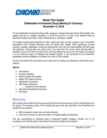
Chapter 2: An Overview of the Allegiant LightbarFigure 2.1 Lightbar 4L1L28125L11DS4L20DS32726252423222120Allegiant Lightbar1918171615PS
Chapter 2: An Overview of the Allegiant LightbarTable 2.4 Lightbar functionsCommand45"53"61"70"DescriptionRight AlleyDefault: L1Cal-Style: L1and 8Default: L1Cal-Style: L1and 10Default: L1Cal-Style: L1and 12Default: L1Cal-Style: L1and 14Steady burns white inthe right alley headsFloods white to the rearof the light barLeft AlleyScene frontDefault: LCal-Style: Land 1Default: L, 1-8,and L1 CalStyle: 2- 7Worklight9-16Takedown(Serial Only)*Positions areconfiguredSteady Red3 and 6(Serial withSSP or SerialIn-terfaceOnly)Signalmaster(Serial Only)10-15Default: LCal-Style: Land 1Default: LCal-Style: Land 1Default: LCal-Style: Land 1Steady burns white inthe left alley headsDefault: L, 1-10, Default: L, 1-12, Default: L, 1-14, Floods white to theL1 Cal-Style:L1 Cal-Style:L1 Cal-Style:front of the light bar.2-92-112-13This option changesdepending on howalleys are configured11-2013-2415-28*Positions areconfigured*Positions areconfigured*Positions areconfigured3 and 83 and 103 and 1212-1915-2218-25Allegiant LightbarSteady burns whitein the configuredtakedown positionsSteady burns the headsIf red in DS and red orblue in PS, it will steadyburnFlashes SignalMaster13
Chapter 3: Reprogramming the LightbarHEAVY OBJECT: Use lifting aids and proper lifting techniques when removingor replacing this product. Failure to follow this warning may cause personalinjury.Carefully unpack the lightbar assembly and any other products included in the shipment.Inspect them for damage that may have occurred during shipping. If a product has beendamaged, do not install or operate it. Immediately file a claim with the carrier describing thedamage.Carefully check all envelopes, shipping labels, and tags before removing or destroying them.If you are missing any parts, contact Customer Support at 1-800-264-3578, 7 am to 5 pm,Monday through Friday (CT).Reprogramming the LightbarAlthough the Allegiant lightbar is configured and programmed at the factory, you may wantchange default settings and flash patterns before you install the lightbar. Before you begin,decide if you want to change these default settings:Serial Bars: MODE 1, 2, 3, and INTERSECTIONMODES 1 through 3 are most often selected by a progressive slide switch, whichenables the driver to turn on the lightbar without looking down. You can select apattern for each mode from the lightbar’s library of 27 patterns.The INTERSECTION flash pattern is typically a high activity pattern that attractsattention to the vehicle as it approaches an intersection. You can select a patternfrom the library and choose one of three ways to turn on and off the pattern. TheINTERSECTION flash pattern overrides the three priority modes.NOTE: If the SignalMaster flash pattern is turned on, it overrides the current flashpattern. FRONT and REAR lights: CUTOFF (default) or ENABLESet these options after you change the default settings for MODE andINTERSECTION flash patterns.CUTOFF turns OFF the front or rear LEDs when 12 Vdc is applied to the FRONT orREAR light control wire. ENABLE turns ON the front or rear LEDs when 12 Vdc isapplied.14Allegiant Lightbar
Chapter 3: Reprogramming the LightbarDiscrete Bars: MODE 1, 2You can select a pattern for each mode from the lightbar’s library of 27 patterns.Making the Electrical Connections for ReprogrammingTo supply power to the lightbar, use a fully-charged 12-volt automotive battery. For Serialbars, follow the instructions supplied with external controller. For SSP, use 25500151; SerialInterface, use 2562248; 6-button, 2562360 and 2562669; 3-button, 2562497.For Discrete, follow these steps:1.Place the lightbar on a sturdy, flat surface.2.Attach the BLACK wire to the negative battery (–GND) terminal.3.Attach the RED and/or YELLOW power line through a fuse rated on Table 3.1 to thepositive battery ( BAT) terminal. If a switch is desired, attach the switch between thefuse and the battery.Table 3.1 Wire functions and fuse requirementsWire ColorFuseFunctionYellow20 ARear Mode 1RedBlueOrangeGrayGreenBrown20 A12 A12 A5A5AWorklight/BedlightScene FrontRight AlleyLeft AlleyN/AMode 2 OverrideBrown/White N/ABlackFront Mode 1DimmingN/AGroundReprogramming the Discrete LightbarThe discrete lightbar can change the flash pattern for Modes 1 and 2. To change the flashpattern:1.Attach the BLACK wire to the negative battery (-GND) terminal.2.Turn on the lightbar by applying BAT to the RED and/or YELLOW wire. If Mode 2 isbeing changed, apply BAT to the BROWN wire as well.3.Quickly tap the BROWN/WHITE wire to BAT three times.4.Tap the BROWN/WHITE wire once to change to the next pattern. The pattern will bedimmed while the BROWN/WHITE wire is held to BAT as a visual feedback.5.Repeat step 4 until the desired pattern is selected.Allegiant Lightbar15
Chapter 3: Reprogramming the Lightbar6.Turn the lightbar off. Wait at least 5 seconds and Turn the lightbar on. Check that thepattern has been saved.Mode 1 flash patterns are listed at Table 3.2.Mode 2 enables flashing white to the front by default. It can be reprogrammed to a differentflash pattern with OR without flashing white. See Table 3.3 for the pattern list for Mode 2.Table 3.2 Allegiant Patterns#Description #Description#Description2Pattern 2*Pattern 1222Pattern 221345678910Pattern 1*11Pattern 3*13Pattern 4*Pattern 5*Pattern 6*Pattern 7Pattern 8*Pattern 9Pattern 10121415
and servicing the Allegiant lightbar. The safety messages presented in this chapter and throughout the manual are reminders to exercise extreme care at all times. In addition, read and understand the safety instructions and keep it