Transcription
LEAVE THIS PAGE BL ANKDO NOT DELETE THIS PAGEREALIGNMENTS1
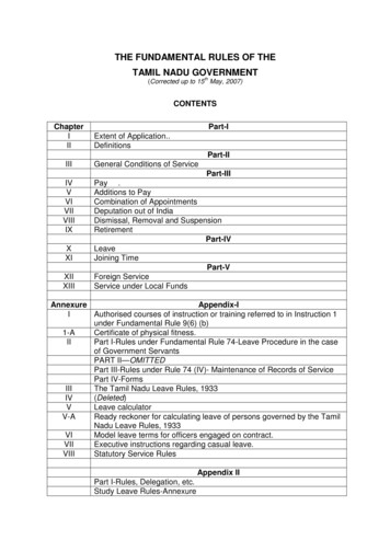
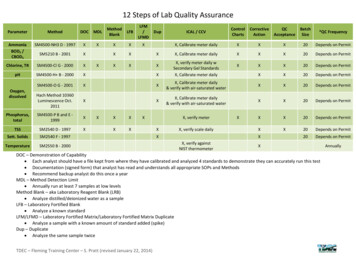
Kerf Bending and Zipper in SpatialTimber TectonicsYulun Liu*A Polyhedral Timber Space Frame System Manufacturable by3-Axis CNC Milling MachineUniversity of PennsylvaniaUniversity of PennsylvaniaYao Lu*University of PennsylvaniaMasoud Akbarzadeh*Authors contributed equally1ABSTR ACTSpace frames are widely used in spatial constructions as they are lightweight, rigid, andefficient. However, when it comes to the complex and irregular spaces frames, they can bedifficult to fabricate because of the uniqueness of the nodes and bars. This paper presents a novel timber space frame system that can be easily manufactured using 3-axisCNC machines, and therefore increase the ease of the design and construction of complexspace frames. The form-finding of the space frame is achieved with the help of polyhedralgraphic statics (PGS), and resulted form has inherent planarity which can be harnessed inthe materialization of the structure. Inspired by the traditional wood tectonics kerf bendingand zippers are applied when devising the connection details. The design approach andcomputational process of this system are described, and a test fabrication of a single nodeis made via 3-axis CNC milling and both physically and numerically tested. The structuralperformance shows its potentials for applications in large-scale spatial structures.2ACADIA 20211One branch of the bar showsKerf-bending part and Zipperednode
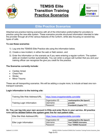
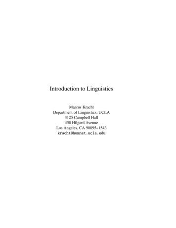
INTRODUCTIONSpace frames are widely used in spatial constructions asthey are lightweight, rigid, and efficient. Despite the factthat the systematic development of specialized productionmethods and digital fabrication technology has enabledthe construction of timber structures to reach a new level(Lennartz and Susanne 2015), the fabrication of suchspatial structure is still not easy due to the uniquenessof bars and nodes, and always involves robotic fabrication, multi-axis machining, 3D printing as well as casting.The diverse nodes of some branching wooden structuralsystems are produced by flip-milled on a CNC router(Lamere and Gunadi 2019), and other spatial wooden structures introduce steel sleeve anchor or tension rods to helpconstruct the nodes (Momoeda 2017; Teeple 2015).2To reduce the complexity of the design and fabricationof space structures, this paper presents a novel timberspace frame system that blurs the boundary between barsand nodes and can be milled simply by 3-axis CNC millingmachines. This system incorporates the traditional manufacturing techniques of kerf bending and dovetailed jointsand introduces a new connection using zippered wood. Theform-finding process is achieved with the help of polyhedral graphic statics (PGS) as the inherent planarity of theresulted form is required for developing the structuraldetails.3Kerf-bending and zippered-woodIn practice, there are many techniques to bend a piece ofwood into the desired curvature. One way to easily createthe precise bending wood surface is the relief-cuttingprocess known as kerfing (Mansoori et al. 2019). It is awell-established carpentry technique for producing curvedwooden pieces in a wide range of applications. By cutting aseries of deep notches (or kerfs) at the bending area allowsfor in-plane expansions and compressions perpendicular tothe cutting lines (Figure 2). If the two edges of each kerf onthe compression side are tightly attached, a mathematicalrelationship can be found among the angle of bending, thethickness of the wood, and the dimension of cutting slots.The zippered wood connection was inspired by dovetailedjoints which provide interlocking between the componentswhile hiding the connection details. A series of ‘pins’ cutto extend from the end to interlock with a series of ‘tails’from another board (Figure 3). This connection can not onlyaccommodate the orientation change of the bars but alsoachieve the desired curvature and twisting (Satterfield etal. 2020).TOPIC (ACADIA team will fill in)42Kerf-bending technology allowsthe rigid wood to bend by thedesired angle when the pairof edges of each kerf is tightlyattached.3Dovetail joint manufacturedusing classic technology, highlighted are fraction surfaces.4(a) a spatial structural joint inequilibrium, and the reciprocalrelationship between polyhedral form and force polyhedron(Akbarzadeh et al. 2019); (b) thefirst built structure designedby using 3D Graphic Staticsmethods (Akbarzadeh et al.2017; Bolhassani et al. 2018)(Courtesy of PSL).Polyhedral graphic staticsGeometric structural design methods depend on 2D reciprocal diagrams are regarded as a compelling design toolthat has long been studied and practiced. The geometricinterrelation between force and form was initially proposedby Rankine (1864), and Maxwell (1870) formulated thetopological and reciprocal relationship as reciprocal formand force diagrams. The development of 3D graphic statics(3DGS) further increased the ease of designing complexspatial structures. In the realm of 3DGS, the methoduses polyhedral reciprocal diagrams, usually referredto as polyhedral graphic statics (PGS), has recently beenREALIGNMENTS3
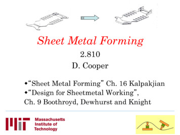
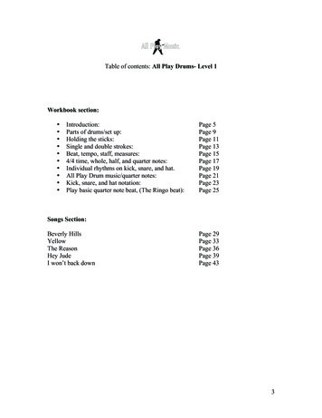
575The form can be manipulated bychanging the force diagram.6Fast queries of geometric andtopological information aremade possible through the halfface data structure.7(a) Spatial node with four bars;(b) edges and faces; (c) triangular section profile for oneedge determined by connectedthree faces; (d) aligned view forthe edge section; (e) side faceperpendicular to the corresponding input face; (f) all sidefaces perpendicular to theircorresponding input faces; (g)Spatial node with five bars; (h)tetragonal section profile for oneedge determined by connectedfour faces; (i) final generatedparts.6developed and extended (Akbarzadeh 2016; Akbarzadeh etal. 2015a; McRobie 2016;). It provides methods to find theequilibrium of structure in 3D by enforcing the closenessof the global force polyhedron and nodal force polyhedrons,and the reciprocity is built by projecting form polyhedronsto force vertices, form faces to force edges, form edgesto force faces, form vertices to force polyhedrons, wherethe force magnitude of each edge in the form polyhedronis equivalent to the area of the corresponding face in theforce polyhedron (Figure 4). The inherent planarity of thepolyhedral geometries has the potentials to be harnessedfor efficient construction processes.Form-finding through PGSThis timber space frame system is developed upon polyhedral forms as the intrinsic planarity helps develop the detailof kerf bending. PGS is used because it allows manipulatingthe form while being aware of the internal force distribution. PolyFrame (Version 0.1.9.2; Nejur and Akbarzadeh,2021), an efficient computational PGS plugin forRhinoceros (Version 6.0 SR29; Robert McNeel Associates,2020), together with its underlying half-face data structure(Nejur and Akbarzadeh, 2021) are used throughout thedesign process.This research is an ongoing investigation in the designand construction of timber spatial structures designedby polyhedral graphic statics. The design approach builtupon the reciprocal form and force diagrams of PGS will beexplained in this section. The computational model is implemented using Rhino Python.To start the form-finding process, a set of closed polyhedrons is made as the force diagram, followed by thegeneration of its corresponding form diagram. The simplestframe with one node is used here to demonstrate theadjustment of the form as well as the organization of thegeometrical and topological data (Figure 5). Through thehalf-face data structure, fast queries of needed informationare made possible (Figure 6).4Kerf Bending and Zipper in Spatial Timber Tectonics, LiuDESIGN METHODOLOGYACADIA 2021
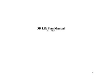
8109118(a) One part of the frame withkerf-bending portion and zipperteeth; (b) the part after bendingwith the edge pair of each kerftightly attached.10 The assembly sequence.(a)The logic of generatingzippered ‘tooth’ and the mode ofpatterns for triangle and quadrangle cross-section; (b)(c)(d)(e)details for the three-directionalzippered part.12 (a) The force diagram of a table;(b) the form diagram of the table;(c) the force diagram of a shell;(d) the form diagram of the shell.1211 The connection between twoneighboring joints.Materializationcorresponding edge and the magnitude of its force. Takingone edge from the form diagram, the number of sides of theprofile is determined by the count of the connected faces;the direction of each side is determined by the normal of thecorresponding face; the area of the profile is proportionalto the internal force of the edge. For instance, if the edgeconnects to 3 faces, the profile will be triangular (Figure7b 7d,); if the edge connects to 4 faces, the profile will bequadrangular (Figure 7g i).After getting the form diagram (Figure 7a), the edges arematerialized into timber bars. The cross-section of eachbar is determined by both the connected faces of theLater, a smooth singly curved blend is generated for eachpair of bar sides that are connected and sharing the9TOPIC (ACADIA team will fill in)REALIGNMENTS5
13same face, forming the kerf bending node that joins allthe connected bars (Figure 7e). Then, the side extrusionsof each bar as well as the zipper teeth are made alongthe corresponding edge, whose details will be describedlater. Finally, all the geometries that are associated witheach face will be grouped and fabricated as one part. Asa result, this simple spatial structure with four bars andone node can be made by only six parts (Figure 7f). Sinceboth the extrusion and kerf bending portions of each partare perpendicular to the same face, it can be unrolled andfabricated from flat material (Figure 8).14The zippered teeth are located on the interior side of thestraight segment of each part, serving as the mechanismthat interlocks all side parts that compose each bar.As a further description of the interlocking zipper teeth, thegeneration of the tooth patterns for one bar is illustratedas follows (Figure 9). First, the length of the bar is evenlydivided into a number of segments. Then, the profile of thebar is split into triangles by connecting its centroid to allcorners. Next, the centroid of each triangle is successivelyused as the new splitting point for the tooth pattern of the6ACADIA 202113 Renderings of a funicular shelland a desk.14 Assembly process of the teeth ofa bar.1515 (a) one part; (b) three parts afterassembly; (c) cross-section of abar.Kerf Bending and Zipper in Spatial Timber Tectonics, Liu
17181616 One whole joint after assembly.segments, and consequently, the interlocking teeth arecreated.For kerf cuttings, the cutting depth, cutting width, and kerfcount are the 3 key parameters that determine the curvature of the bending. They need to be calculated accordinglysuch that the 2 exterior edges of each kerf are tightlypressed together after bending (Figure 9b).The material properties and fabrication constraints arealso considered parallel alongside the geometrical development of the space frame system. Timber is selected as theconstruction material because of its sustainability and easeof processing. All geometries of the structural parts aregenerated in the way that only the table saw and 3-axis CNCmilling machine are needed for rapid fabrication, wherethe table saw cuts the kerfs and the 3-axis CNC millingmachine carves the teeth. It’s also manufacturable by a3-axis CNC milling machine only with flip milling technique.The assembly of the frame is illustrated in Figure 10, anda bonding agent is required on the interface between theparts.18 (a) Set-up for load test (b) topview of the set-up.17 Details of the kerf-bending part.nodes, the workflow described above can also be appliedto complex polyhedral space frames with more bars andnodes. As shown in Figure 11, the two adjacent nodesshare the same bar. By varying the contact location of thesides, an interlock is created between these nodes, andthe contact area is increased. As case studies, a compression-only funicular shell and a table are generated usingthe workflow proposed above (Figure 12 13).FABRICATION AND E XPERIMENTSThe strength and stiffness of the proposed system needto be carefully investigated as the bending part is madevulnerable due to the kerfs. To evaluate its structuralperformance, a frame prototype with 4 bars and 1 node isfabricated, assembled, and tested through both physicaland numerical methods. The overall fabrication processwould use the 3-axis CNC milling machine for the zipperedshape and table saw for cutting the wood.FabricationThe application in multi-node polyhedral formsWith a connection devised between every two neighboringTOPIC (ACADIA team will fill in)The simple frame is built within the 450x400x360 mmbounding box, and 3/4" thick plywood is used.REALIGNMENTS7
distribution and displacement of the prototype underheavier loads. A total load of 1 KN is applied to the top barwhile the bottom 3 bars are fixed at the end. The resultshows stress concentrating on the exterior side of thekerfs, where the maximum stress is 34.93 MPa and themaximum displacement is 0.006mm (Figure 20).19CONCLUSIONThis paper introduces a novel timber space frame systemby combining kerf bending with zippered wood, which canbe easily manufactured by accessible tools like 3-axis CNCmilling machines. The assembly is also made easy since nojig or locator is needed. This system greatly facilitates thedesign and fabrication of complex timber space frames andallows for rapid fabrication and construction. A computational pipeline is also developed based on PGS for fastmodeling and user-friendly parameter control.2019 Physical load test for the prototype; (a) 50 pounds of appliedload (b) 70 pounds of appliedload (c) 90 pounds of appliedload.20 (a) Displacement map; (b) stressdistribution map; (c) detail ofmaximum stress point afterbearing the force of 1KN.Although each part is manufacturable as a whole, thezipper teeth of each part are separately made and gluedback in this prototype for a faster fabrication (Figure 14,Figure 15a). For the kerf-bending part, the slots are cut by a1/8” table saw. For the zipper teeth, appropriate tolerancesneed to be left to ensure the tight interlocking. Figure 15 (a)shows one part of the assembly, and Figure 15 (b)(c) showone assembled bar by interlocking and bonding three partstogether. As explained before, all the exterior edges of eachkerf are pressed together after the assembly, and bondingagents are applied to fix the curvature and strengthen thestructure (Figure 16 17).The outcome of both the physical test and numerical simulation show promising structural performance in terms ofthe little deformation under the heavy loads. It also contributes towards the applications of polyhedral graphic staticsin materialization and construction.ACKNOWLEDGEMENTSThis research was generously supported by the PolyhedralStructures Lab at Weitzman School of Design, University ofPennsylvania. We thank Masoud Akbarzadeh for his support andadvising, and Edyta Augustynowicz for offering valuable consultation and expertise.REFERENCESAuthors should refer to both the Chicago Manual of Style, and thePhysical testDue to the limited accessibility of testing machines, a simpleloading test is conducted to study the strength and stiffnessof the prototype. The supports are 3d-printed and screwedon a wood panel to confine the 3 bottom bars from anylateral movement (Figure 18). The self-weight of this prototype is 857g, and after applying a total load of 90 poundson the top bar, there is no visible buckling or deformation,which shows the potentials of its load-bearing capacity(Figure 19). To further understand its structural performance and limit, a universal testing machine will be usedfor the next step to complete an accurate experiment.examples below.Akbarzadeh, M. 2016. “3D graphic statics using polyhedral reciprocal diagrams.” PhD thesis.Akbarzadeh, Masoud, Tom Van Mele, and Philippe Block. 2015a. "3Dgraphic statics: geometric construction of global equilibrium." InProceedings of IASS Annual Symposia, vol. no.21, pp. 1-9.Akbarzadeh, Masoud, Tom Van Mele, and Philippe Block. 2015b. "Onthe equilibrium of funicular polyhedral frames and convex polyhedral force diagrams." Computer-Aided Design 63: 118-128.Numerical simulationAkbarzadeh, Masoud, Mohammad Bolhassani, Andrei Nejur, JosephThe Autodesk Fusion 360 is used to simulate the stressRobert Yost, Cory Byrnes, Jens Schneider, Ulrich Knaack, and Chris8Kerf Bending and Zipper in Spatial Timber Tectonics, LiuACADIA 2021
Borg Costanzi. 2019. "The design of an ultra-transparent funic-Satterfield, Blair, et al. "Bending the Line Zippered Wood Creatingular glass structure." In Structures Congress 2019: Blast, ImpactNon-Orthogonal Architectural Assemblies Using The Most CommonLoading, and Research and Education, pp. 405-413. Reston, VA:Linear Building Component (The 2X4)." In Fabrication 2020 - MakingAmerican Society of Civil Engineers.Resilient Architecture, ed. J. Burry et al. London: UCL Press. 58-65Akbarzadeh, Masoud, Mehrad Mahnia, Ramtin Taherian, and AmirNejur, A., and M. Akbarzadeh. 2018. "Polyframe beta: a geome-Hossein Tabrizi. 2017. "Prefab, Concrete polyhedral frame: materi-try-based structural form finding plugin for rhinoceros3d."alizing 3D graphic statics." In Proceedings of IASS Annual Symposia,A. Nejur and M. Akbarzadeh. PolyFrame, Efficient Computationvol. 2017, no. 6, pp. 1-10. International Association for Shell andfor 3D Graphic Statics. Computer Aided Design, 134:103003, MaySpatial Structures (IASS).2021.Bolhassani, Mohammad, Masoud Akbarzadeh, Mehrad Mahnia,Robert McNeel Associates. Rhinoceros 6.0. Available: https://and Ramtin Taherian. 2018. "On structural behavior of a funicularrhino3d.comconcrete polyhedral frame designed by 3D graphic statics." InStructures, vol. 14, pp. 56-68. Elsevier.Rankine WJM. 1864. “Principle of the Equilibrium of PolyhedralIMAGE CREDITSFrames.” Philos Mag Ser 4 27(108): 92.McRobie, Allan. 2016. "Maxwell and Rankine reciprocal diagramsvia Minkowski sums for two-dimensional and three-dimensionaltrusses under load." International Journal of Space Structures31.2-4: 203-216.Maxwell, J. Clerk. 1870. "I.—on reciprocal figures, frames, anddiagrams of forces." Earth and Environmental Science Transactionsof the Royal Society of Edinburgh 26.1: 1-40.Joel Lamere and Cynthia Gunadi. 2019. “Lost House” In ACADIA2019: Ubiquity and Autonomy, Paper Proceedings of the 39thAnnual Conferenceon the Association for Computer Aided Design inArchitecture (ACADIA), Bieg, Kory, Briscoe Danielle and Odom Clay.140-145. Mexico City: ACADIA.Yu Momoeda. 2017. “Agri Chapel / Yu Momoeda ArchitectureOffice” ArchDaily. Accessed 8 July 2021.Teeple Architects. 2015. "Philip J. Currie Dinosaur Museum /Teeple Architects”. ArchDaily. Accessed 8 Jul 2021.Capone, Mara, and Emanuela Lanzara. 2019. "Parametric KerfBending: Manufacturing Double Curvature Surfaces for WoodenFurniture Design." Digital Wood Design. Springer, Cham. 415-439.Mansoori, Maryam, et al. 2019. "Adaptive wooden architecture.Designing a wood composite with shape-memory behavior." Digitalwood design. Springer, Cham. 703-717.Sebera, Vaclav, and Milan Šimek. 2014. "Finite element analysis ofdovetail joint made with the use of cnc technology." Acta universitatis agriculturae et silviculturae mendelianae brunensis 58, no. 5:321-328.TOPIC (ACADIA team will fill in)Figure 4: Masoud Akbarzadeh, 2017All other drawings and images by the authors.Yulun Liu is an interdisciplinary designer with an interest instructural design and spatial efficiency. She is currently a Masterof Architecture candidate at the Weitzman School of Design,University of Pennsylvania. She also holds a Master of StructuralEngineering from Tianjin University.Yao Lu is currently a Ph.D. student at the Polyhedral StructuresLaboratory, Weitzman School of Design, University of Pennsylvania.He is a design researcher with a great interest in generative design,robotic fabrication, 3D printing, and computer graphics. Beforejoining PSL, he graduated from Cornell University with a Masterof Science in Matter Design Computation. He also holds a Masterof Architecture and a Bachelor in Engineering degrees and fromTongji University.Masoud Akbarzadeh is a designer with a unique academicbackground and experience in architectural design, computation, and structural engineering. He is an Assistant Professorof Architecture in Structures and Advanced Technologies andthe Director of the Polyhedral Structures Laboratory (PSL). Heholds a D.Sc. from the Institute of Technology in Architecture, ETHZurich, where he was a Research Assistant in the Block ResearchGroup. He holds two degrees from MIT: a Master of Science inArchitecture Studies (Computation) and a MArch, the thesis forwhich earned him the renowned SOM award. He also has a degreein Earthquake Engineering and Dynamics of Structures from theIran University of Science and Technology and a BS in Civil andEnvironmental Engineering. His main research topic is ThreeDimensional Graphical Statics, which is a novel geometric methodof structural design in three dimensions.REALIGNMENTS9
Kerf-bending and zippered-wood In practice, there are many techniques to bend a piece of wood into the desired curvature. One way to easily create the precise bending wood surface is the relief-cutting process known as kerfing (Mansoori et al. 2019). It is a